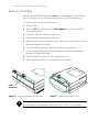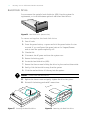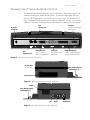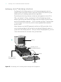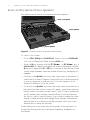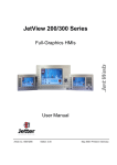
1
User’s Guide
1
Thank you for purchasing this Factory Service
Manual CD/DVD from servicemanuals4u.com.
Please check out our eBay auctions for more great
deals on Factory Service Manuals:
servicemanuals4u
2
Gateway Solo™ 2200 Multimedia Notebook
Contents
Legal notices .............................................................. 4
Specifications .............................................................. 6
If you don’t read anything else . . . Read this! ....................................... 8
System Overview .......................................... 9
Outside the System ......................................................... 10
Inside the System .......................................................... 12
Getting Started .......................................... 13
Connecting the Power ......................................................
Powering up the System .....................................................
Power button setting ....................................................
Batteries ................................................................
Charging/discharging the battery pack ........................................
Battery status ..........................................................
LCD Display ..............................................................
Keyboard ................................................................
Key combinations/hot keys ................................................
EZ Pad Pointing Device ......................................................
Customizing the EZ Pad ..................................................
Windows 95 .............................................................
Start button ...........................................................
Task bar ..............................................................
If you need additional help: ................................................
14
15
15
17
17
17
19
20
20
24
25
26
27
27
27
Modularity/Connectivity ................................... 29
Battery Pack Bay ...........................................................
Modular Option Bay ........................................................
Modular CD-ROM, floppy disk drive, and battery pack .............................
Swapping modules ......................................................
External Floppy Drive Adapter .................................................
Hard Disk Drive ...........................................................
Memory ................................................................
PC Cards ................................................................
Connections ...........................................................
FastIR port ............................................................
Gateway Solo™ mini-docking station ............................................
Gateway Solo™ docking station ................................................
30
31
31
32
33
34
35
37
38
38
39
40
User’s Guide
3
Using the System ........................................ 41
Built-in Microphone/Stereo Speakers .............................................
Making an Audio Recording ..................................................
Playing a MIDI file ..........................................................
Playing external MIDI modules or keyboards..................................
Using the Composite Video Out port ............................................
Using Fast IR Port ..........................................................
Playing an Audio CD .......................................................
Using a Modem ...........................................................
42
43
44
47
48
48
49
50
Advanced Topics ......................................... 51
Power-Saving Modes .......................................................
Standby mode .........................................................
Suspend/Resume mode...................................................
Rebooting ............................................................
Setup Menus .............................................................
Main menu ...........................................................
Advanced menu ........................................................
Security menu .........................................................
Power menu ..........................................................
Exit menu ............................................................
Popup Status Display .......................................................
Port/IRQ Configurations .....................................................
52
52
52
52
53
54
56
58
61
63
64
65
Accessories ............................................. 67
Maintenance/Troubleshooting .............................. 69
Care and Maintenance ......................................................
Virus Checking ............................................................
Hard Drive Utilities .........................................................
Disk defragmenter ......................................................
ScanDisk .............................................................
Reformatting the Hard Disk Drive ...............................................
Troubleshooting ...........................................................
Start up ..............................................................
General ..............................................................
Frequently asked questions ................................................
Important Information ......................................................
Calling Gateway 2000 U.S. ................................................
Calling Gateway 2000 outside the U.S. ........................................
70
71
72
72
72
73
74
74
75
76
78
79
79
Index .................................................. 80
4
Gateway Solo™ 2200 Multimedia Notebook
Legal notices
Gateway Solo™ 2200 Multimedia Notebook
User’s Guide
Copyright © 1996
Gateway 2000®
610 Gateway Drive
North Sioux City, SD 57049 USA
All rights reserved
FCC statement
This book is protected by copyright and all rights are
reserved. No part of it may be reproduced or transmitted by any means or in any form without prior written
consent from Gateway 2000.
Note: This equipment has been tested and found to
comply with the limits for a Class B digital device
pursuant to Part 15 of the FCC Rules. These limits are
designed to provide reasonable protection against
harmful interference in a residential installation. This
equipment generates, uses, and can radiate radio
frequency energy and, if not installed and used in
accordance with the instructions, may cause harmful
interference to radio communications. However, there is
no guarantee that interference will not occur in a
particular installation. If this equipment does cause
harmful interference to radio or television reception,
which can be determined by turning the equipment off
and on, the user is encouraged to try to correct the
interference by one or more of the following measures:
The information in this manual has been carefully
checked and is believed to be accurate. However,
Gateway 2000 assumes no responsibility for any
inaccuracies that may be contained in this manual. In
no event will Gateway 2000 be liable for direct,
indirect, special, incidental, or consequential damages
resulting from any defect or omission in this manual,
even if advised of the possibility of such damages.
In the interest of continued product development,
Gateway 2000 reserves the right to make improvements in this manual and the products it describes at
any time, without notice or obligation.
Trademark acknowledgments
AnyKey, cow spot motif, CrystalScan, Destination,
Gateway 2000, HandBook, RIDE, Store-On-A-Disc,
TelePath, Vivitron, stylized “G” design, and motto
“You’ve got a friend in the business” are registered
trademarks of Gateway 2000. ColorBook, EZ Pad, EZ
Point, Family PC, Gateway 2000 Duoline, Gateway
2000 Solo, GW2K, and Liberty are trademarks of
Gateway 2000. Intel is a registered trademark of Intel
Corporation. Microsoft, MS, MS-DOS, and Windows are
trademarks or registered trademarks of Microsoft
Corporation. All other product names mentioned
herein are used for identification purposes only, and
may be the trademarks or registered trademarks of
their respective companies.
u
Reorient or relocate the receiving antenna
u
Increase the separation between the equipment
and receiver
u
Connect the equipment into an outlet on a circuit
different from that to which the receiver is connected
u
Consult an experienced radio/TV technician for
help.
Caution: Changes or modifications not expressly
approved by the party responsible for compliance could
void the user’s authority to operate the equipment.
To meet FCC requirements, shielded cables are required
to connect this device to any other Class B certified
device.
INDUSTRY CANADA Notice — For the customers in Canada
This apparatus complies with the Class B limits for radio noise
emissions set out in Radio Interference Regulations.
INDUSTRIE CANADA Notice — Pour les utilisateurs au Canada
Cet appareil est conforme aux normes Classe B pourbruits
radioélectriques, spécifiés dans le Règlement sur le broullage.
User’s Guide
5
Cautions and Warnings
Caution: Danger of explosion if battery is incorrectly
replaced. The battery can pose a fire or chemical burn
hazard if mistreated. Do not disassemble, heat above
60°C (140°F), or incinerate. Replace only with the
same or equivalent type recommended by the manufacturer. Dispose of used batteries promptly and
according to the manufacturer’s instructions.
Attention: Il y a danger d’explosion s’il y a replacement
incorrect de la batterie. Remplacer uniquenment avec
une batteries du meme type ou d’un type
recommande par le constructeur. Mettre rebut les
batteries usagees conformement aux instructions du
fabricant.
Vorsicht: Explosionsgefahr bei unsachgemäßem
Batteriewechsel. Originalbatterien nur durch gleiche
oder vom Hersteller empfohlene Batterien ersetzen.
Gebrauchte Batterien an Gateway 2000 zurücksenden.
Advarsel: Eksplosjonsfare ved feilaktig skifte av batteri.
Benytt samme batteritype eller en tilsvarende type
anbefalt av apparatfabrikanten. Brukte batterier
kasseres i henhold til fabrikantens instruksjoner.
Caution: Replace the cord if it becomes damaged. U.S.
and Canadian replacement cords must be UL-approved
(CSA certified in Canada) type SPT-2, 18 AWG, 2conductor cord with permanently attached NEMA type
1-15P plug at one end and a permanently attached S1
connector body on the other. Cord length may not
exceed 15 feet. Outside the U.S. and Canada the cord
must be rated for at least 250VAC at 10 amps, and
must indicate international safety agency approval. The
plug must be a type appropriate for the country of use.
Obtain replacement cords at an authorized service
center. The replacement must be of the same type and
voltage rating as the original cord.
Vorsicht: Beschädigte Kabel ersetzen. Ersatzkabel in den
USA und Kanada müssen folgende Bedingungen
erfüllen: UL-anerkannter (in Kanada CSA-zertifizierter)
SPT-2 Typ, 18 AWG, 2-Leiter-Kabel mit fest installiertem
NEMA-Typ-1-15P-Stecker und fest installierter
Anschlußdose am anderen Ende, max. 4,57 m Länge.
Außerhalb der USA und Kanada gelten folgende
Bedingungen: Kabel für mindestens 250 V
Wechselstrom bei 10 A, anerkannt durch internationale
Sicherheitsbehörde, landesspezifischer Stecker.
Ersatzkabel nur im Fachhandel erwerben. Nur
Ersatzkabel des gleichen Typs und für die gleiche
Spannung (Voltzahl) wie das Originalkabel verwenden.
Warning: Always plug the cord into an easily accessible
outlet near the equipment so that unplugging the cord
is an easy way to shut off power.
Do not attempt to disassemble the AC adapter. The AC
adapter has no user-replaceable or user-serviceable
parts inside. The AC adapter has dangerous voltages
that can cause serious personal injury or death. Return
defective AC adapters to Gateway 2000.
The AC adapter is intended for use with a computer.
Both must meet EN 60950.
Achtung: Netzkabel stets in eine gut zugängliche
Steckdose nahe der Ausrüstung einstecken, um durch
einfaches Ziehen des Steckers jederzeit die
Stromversorgung unterbrechen zu können.
Den Adapter unter keinen Umständen
auseinanderbauen. Der Adapter enthält keine vom
Benutzer zu ersetzenden oder zu wartenden
Bestandteile. Die Spannung im Adapter kann beim
Auseinanderbau zu Verletzungen oder Tod führen.
Beschädigte Adapter an Gateway 2000 zurücksenden.
Der Adapter ist für den Gebrauch mit einem Computer
bestimmt. Adapter und Computer müssen die Norm
EN 60950 erfüllen.
Environmental considerations
Your Gateway Solo 2200 Multimedia Notebook has
been engineered to provide many years of reliable
service. However, you should give it the same reasonable care and protection that you would any other
electronic equipment. Damage caused by dropping the
Gateway Solo 2200 Multimedia Notebook, impact with
another object, or immersion in liquids is not covered
by the warranty. Never expose the Gateway Solo 2200
Multimedia Notebook to rain, snow, or moisture. Avoid
locations with high levels of dirt, dust, or smoke.
CAUTION: DO NOT OPEN. NO USER SERVICEABLE PARTS INSIDE.
ATTENTION: NE OUVRIER PAS. PARTIS RÉPARABLES UNIQUEMENT Á L'USINE.
VORSICHT: NICHT ÖFFNEN. ENTHÄLT KEINE VOM BENUTZER ZU
WARTENDEN BESTANDTEILE.
In our effort to use nature’s resources efficiently and
wisely, Gateway 2000 prints all manuals on recycled
papers that meet the minimum requirements established
by the Federal EPA in its guidelines for recycled paper
products.
Printed in the United States of America
Part # SYSMAN037AAUS
8501164
MAN US SYS SL22 USR GDE
1/97
6
Gateway Solo™ 2200 Multimedia Notebook
Specifications
(Specifications are subject to change without notice or obligation.)
CPU
Cache
Intel Pentium™ 120, 133, 150 MMX or 166 MHz MMX, TCP packaging
256K pipelined burst level 2
RAM
Core logic
EDO; 16MB minimum, expandable to 80MB
Intel 82430MX (Mobile Triton I), PCI bus
Clock frequency
50/60/66MHz
BIOS
Phoenix; 256KB Flash ROM
LCD panel size
LCD panel resolution
11.3″ TFT, 12.1″ TFT
SVGA 800 × 600
LCD panel color depth
TFT: 65,536 colors (16-bit) at SVGA resolution;
External video
Supports simultaneous LCD/External monitor
External video resolution 640 × 480 with 64 million colors to 1280 × 1024 with 256 colors
Video
Chips & Technologies 65554 with DCI/Direct draw capability, GUI motion
video acceleration, continuous X/Y upscaling to 1024× 768, and an
enhanced Bit-BLT engine
Video interface
32-bit PCI bus with 64-bit memory interface
Video memory
2MB EDO RAM
Zoomed video
PC Card connection to zoomed video port
Keyboard
85 keys (U.S.), full size 19mm pitch; 2.7mm travel; provides same functions
as standard Windows 95 AT keyboard; US, UK English, German, French,
and Japanese available
Mouse/Pointer
EZ Pad integrated pointer; PS/2-type connector for external mouse
External ports
Fast IR port, serial port (16550A-compatible), parallel (bi-directional, EPP,
ECP), video, PS/2 keyboard/mouse, docking station connector, PC Card
Type III or two Type I or II card socket, line in, speaker out, and microphone
Battery pack
Li-Ion 35Whrs, 14.4V; or NiMH 33.6Whrs, 9.6V; Batteries can be ”warmswapped“ in the battery bay without rebooting. Recharges in system.
Conforms to APM 1.2 standard
Second battery
Batterylife
A second battery can be installed and charged in the modular drive bay
Approximately 2.5 hours with one battery and Advanced Power Management (APM) enabled
Battery charge time
3.0 hours for either battery pack type
User’s Guide
AC adapter
19VDC, 45W output; auto voltage adjustment between 100 and 240V
Modular drive bay
Internal 1.44MB 3.5″ floppy drive, 5″ CD-ROM drive, or battery pack
Hard disk drive
Removable; accepts 2.5″, 12.5mm hard disk drive; 810MB, 1.0GB, 1.3GB
and 2GB
Hard disk controller
Floppy disk drive
Enhanced IDE, on PCI bus
Removable; 1.44MB 3.5″ floppy drive; ”hot-swappable“ with optional
second battery pack; optional adapter allows external connection
CD-ROM drive
Removable; 8X; XA mode 2 and CD enhanced compatible
Audio chipset
ESS ES1878S audio chip, ES938 sound effects chip, ES690 wavetable
synthesizer chip
Speakers
Speakers built-in to palm rest
Microphone
Omnidirectional microphone under LCD panel on right
Docking solutions
Several solutions offered, including a mini-docking station with the following: one serial, one parallel, VGA output, DC-in, line in, microphone in,
headphones out, PS/2 keyboard, PS/2 mouse, MIDI/game port, PC Card
slots for one Type III or two Type II; ”hot-dockable“
Accessories
AC adapter; IR (infrared) module; Nickel Metal Hydride (NiMH) battery,
lithium-Ion (Li-Ion) battery; docking station solutions; automobile DC
adapter; hard drives; memory modules; external floppy disk drive adapter;
leather carrying case, nylon carrying case; external speakers; modem;
ethernet cards
Dimensions
Weight
(W × D × H) 11.3″ × 8.97″ × 1.93″ (288mm × 228mm × 49mm)
System weight:
6.9 lbs with battery and CD-ROM drive
Traveling weight: 7.7 lbs with battery, CD-ROM drive and AC adapter
Operating temperature
5 to 35°C
Storage temperature
Operating humidity
-20 to 60°C
20 to 80%; noncondensing relative humidity
Storage humidity
8 to 90%; noncondensing relative humidity
Operating altitude
8000 feet; nonpressurized
(Doesnot refer to pressurized commercial aircraft)
Storage altitude
40,000 feet; nonpressurized
Certification
FCC Class B, UL1950, TUV/EN60950, CSA 22.2
Many Gateway 2000 products are custom engineered by our suppliers to Gateway 2000 specifications, and may vary
with similarly marketed products.
7
8
Gateway Solo™ 2200 Multimedia Notebook
If you don’t read anything else . . . Read this!
Your Gateway Solo™ 2200 Multimedia Notebook provides all the power and
multimedia capabilities of a full-size desktop system, yet allows you the
convenience of a lightweight portable notebook.
The Gateway Solo 2200 contains the following special features:
Wavetable Synthesis — One of two options for playing MIDI files, the
wavetable synthesizer uses digital samples (recordings) of actual instruments
for a more realistic sound quality.
System Modularity — The system has a modular option bay that accepts
either a floppy disk drive module, a CD-ROM module or an additional battery
pack.
Floppy Disk Drive Module — An optional external adapter allows you to use
the floppy disk drive module and CD-ROM at the same time, or use the
floppy disk drive module with an additional battery pack.
Memory Modules — Install additional modules with ease.
Hard Drive Modules — To swap out the hard drive with another hard drive.
Optional Docking Solutions — Use to save time by plugging in peripherals
and leaving them plugged in. The docking solutions easily connect to the
rear of the system, enabling all attached peripherals.
Dual Battery Operation — To operate with two batteries at the same time,
install one battery pack in the battery bay and an optional second battery
pack in the modular option bay. This option is ideal when you travel, providing additional hours of uninterrupted use.
Backup Password Protection — Selecting this option from the Security menu
in the Setup menus will allow you to access your system if you have forgotten your password. Place and store the supervisor password on a diskette in
a hidden file.
Popup Status Display — Through a set of hot key options you can monitor
battery status, temporarily change the power management level, view AC
adapter connection, view mute function enabled/disabled, change volume
settings, or change brightness levels.
Zoomed Video — The video information for most PC Cards goes through
the CPU or system bus, taking up additional processing time. Zoomed video
routes the video information directly to the video card, freeing up the processor for other tasks.
User’s Guide
1
System Overview
Outside the System.................. 10
Inside the System ................... 12
9
10
Gateway Solo™ 2200 Multimedia Notebook
Outside the System
Take a quick tour of the system to familiarize yourself with the options
available.
Cover latch
Modular option bay:
CD-ROM module installed.
Battery bay
Figure 1. Front View
Rubber foot
Retaining pin guide hole:
For optional docking station.
Figure 2. Bottom View
Modular option bay
release latch
Retaining pin guide hole:
For optional docking station.
Battery bay
release latch
Expansion memory
access panel
Rubber foot
Hard drive
access cover
User’s Guide
Power Connector:
Connect the AC
adapter here.
Floppy/ParallelPort:
Connect an external floppy
diskdriveorotherparallel
devicehere.
11
SerialPort:
Connect any serial
devicehere.
240-Pin Docking Station Port:
Connect optional docking station
solutionshere.
VGA Port:
Connect any standard
monitor here.
Figure 3. Rear View
Fast IR port:
Place the transmitter/receiver within
two feet so it can “see” the port.
Mic:
Connect an external
microphone here (disables
internal microphone).
Linein:
Connect
external audio
source here.
Composite Video out
port:(RCA phono jack
connector)
Headphones:
Connect headphones or
external speakers here
(disables built-in speakers).
Figure 4. Right Side View
PC Card eject buttons
Figure 5. Left Side View
PC Card slots:
Accepts two Type I
or Type II cards or
oneTypeIIIcard.
Hard drive access
Kensington lock slot
PS/2 port:
Connect an
external mouse or
keyboard here.
12
Gateway Solo™ 2200 Multimedia Notebook
Inside the System
LCD color display:
11.3-inchTFT,or
12.1-inchTFT
System LEDs
Built-in microphone
Power button
Stereo speakers
Full-sized keyboard:
Windows 95 keys and
special function keys.
Stereo speakers
Battery bay
Figure 6. Interior View
EZ Pad™ pointing device:
Controls the cursor like a
mouse.
Power LED
Battery charging
power LED
Caps Lock LED
Pad Lock LED
Figure 7. System LEDs
Modular option bay:
Floppy disk drive
module installed,
accepts CD-ROM or
second battery.
Scroll Lock LED
Floppy disk
drive LED
Hard disk
drive LED
User’s Guide
13
2
Getting Started
Connecting the Power ............... 14
Powering Up the System ............. 15
Batteries .......................... 17
LCD Display....................... 19
Keyboard ......................... 20
EZ Pad............................ 24
Windows 95 Basics.................. 26
14
Gateway Solo™ 2200 Multimedia Notebook
Connecting the Power
The first time you use the Gateway Solo™ 2200 Multimedia Notebook, use
the AC adapter to fully charge the battery and provide the system with a
constant supply of power.
Caution: Replace the power cord if it becomes damaged. The replacement
cord must be of the same type and voltage rating as the original cord.
To connect the AC adapter to the system:
1. Plug the AC adapter into the system’s power connector.
2. Connect the power cord to the AC adapter.
3. Plug the power cord into an electrical outlet.
AC adapter
Power cord
Figure 8. AC Power Connection
Warning: Do not attempt to disassemble the AC adapter. The AC adapter
has no user-replaceable or user-serviceable parts inside. The AC adapter has
dangerous voltages that can cause serious personal injury or death. Return
defective AC adapters to Gateway 2000.
User’s Guide
15
Powering up the System
Slide the latch on the front face of the system to the right to release the
cover, and open up the system. The power button is located in the upper left
corner on the notebook surface.
The power button on your system is preset in On/Off mode. However, you
can set it to function either inOn/Off orSuspend/Resume mode. This setting
affects the manner in which your system operates.
Power button
Figure 9. Locating the Power Button
Power button setting
When the power button setting in the Power menu is On/Off and:
u the system is off, press the power button to turnOn the computer.
u the system is on, press the power button to turn the computercompletelyOff.
Remember, turning the system completely off when the power button is
set for On/Off mode causes every part of the computer to power down.
Any unsaved work will be lost! Pressing the power button willreboot the
system.
When the power button setting in the Power menu is Suspend/Resume
and:
u the system is off (in Suspend mode), press the power button toResume
power to the computer.
u the system is on, press the power button to cause the computer to enter
Suspend mode.
16
Gateway Solo™ 2200 Multimedia Notebook
u Press and hold the power button for two seconds to turn the system
completely Off.
Caution: Any unsaved work can be lost if you hold the power button down
for too long.
Remember, when the system is on and set forSuspend/Resume mode, pressing the power button does not completely turn off the computer and the
system does not reboot. You must press and hold the power button for
two seconds to completely power down the system.
To check/change the power button setting:
1. Turn the system on.
2. Press the F2 key when you see the message Press <F2> to access
SETUP in the lower left corner of the display, before Windows 95 loads,
to access the Setup menus. The system beeps, then the Main menu
appears.
3. Using the Right Arrow key, move to the Power menu.
4. The first available option isPower button mode:. If the setting displayed is
the one you want, go to Step 6.
5. Press theSpacebar to change the setting.
6. Press the ESC key to access the Exit menu.
7. PressEnter toSave changes & exit, then pressEnter again, or use the
Down Arrow key to select any other option.
User’s Guide
17
Batteries
When you first receive your system, the ”smart“ battery is installed in the
battery bay, but will not have a full charge. The battery bay is located in the
right front panel of the system. We recommend that you perform the ”learning cycle“ test outlined in this section. This test ”teaches“ the battery to hold a
longer charge, increases the accuracy of battery gauging and extends the
battery’slife.
Charging/discharging the battery pack
The battery must be installed in the notebook and connected to an AC
power source to charge completely. The battery will charge if the system is
operating, as long as the AC adapter is properly connected. For twice the
battery life, you can install an optional second battery pack in the modular
option bay. The notebook can run on a fully charged battery for about two
and a half hours of normal use before the battery needs recharging.
Two options are offered for powering your Solo: the Lithium Ion (Li-Ion) and
the Nickel Metal Hydride (NiMH). Both need the same Learning Cycle,
require about three hours to fully charge, and are interchangeable.
Note: Your battery performance may vary, depending on power management settings and usage.
To perform a learning cycle test on the battery pack:
1. Charge the batteryuntil the charge light (LED) goes out. You can check
the charge by pressing theFn key together with theF2 (Popup) key,
which activates the popup window and should read “FUL.”
2. Fully discharge the battery pack. Disconnect the AC adapter. Be sure the
CMOS option “Battery low suspend:” is disabled, then run the notebook
until it shuts off (using battery power only).
3. Begin charging the battery pack. Once the notebook has shut off from
Step 2, connect the AC adapter and wait for the charging LED to light.
At this point, the Learning Cycle is complete.
Battery status
You can check battery status several ways.
u Click onStart, Settings and Control Panel. Double click on thePowericon.
You can view the battery status and set power preferences from this
18
Gateway Solo™ 2200 Multimedia Notebook
screen, which stay in effect until they are changed in Windows. Click on
theX in the upper right corner of the screen to close it.
u Press theFn key together with theF2 (Popup) key, or theF5 (PM) key.
The power status display appears in the upper left corner of the display.
This display monitors battery status, power management selection, and
mute function status. BAT1 monitors the status of the battery pack in the
battery bay. BAT2 monitors the status of the optional second battery
pack, which can be installed in the modular option bay. After four seconds of inactivity, the display will disappear.
u Position the cursor over thepower cord (AC) orbattery icon in the lower
right corner of the task bar. A battery status screen will appear. Moving
the cursor anywhere on the display causes the screen to disappear.
u Click twice on thepower cord or battery icon in the lower right corner of
the task bar. A more detailed battery status screen will appear. Click on
theX in the upper right corner of the screen to close it.
When the battery level gets low:
u The system emits three beeps
u The battery charging power LED flashes
u Thebattery icon in the lower right of the task bar has a red ”X“ over it
u Thepower status display appears, flashing a warning in the upper left
corner of the display
u The Low Battery screen appears, advising you to change your battery or
switch to AC power immediately to prevent losing your work.
Once the battery pack is fully discharged, reconnect the AC adapter to the
notebook to recharge the battery.
User’s Guide
19
LCD Display
The Gateway Solo™ 2200 Multimedia Notebook features a built-in, backlit,
color LCD display. This display is either an 11.3-inch TFT or 12.1-inch TFT
display. Each of these SVGA displays provides sharp, crisp resolution and
crystalclearcolor.
Figure 10. LCD Display
Tilt the system’s entire cover forward or backward to adjust the viewing
angle. Press the Fn key together with the Up Arrow and Down Arrow keys to
control display brightness.
Pressing theFn key together with theF1 (Display Off) key will toggle off the
display and save power. Press any key to reactivate the display.
A few small dots of color may occasionally appear on the screen. This is
normal and does not affect the overall screen image.
Connect an external monitor to the computer through the VGA port on the
rear of the system or the VGA port on the optional mini-docking station.
Press the Fn key with the F3 (LCD/CRT) key to toggle between active
displays.
Note: This system ships with theAuto dim with battery only feature enabled.
Auto dim cuts LCD power 50% when the system is operating on battery
power.
20
Gateway Solo™ 2200 Multimedia Notebook
Keyboard
The Gateway Solo™ 2200 Multimedia Notebook features an 85-key keyboard. To provide the full functionality of a 101/102-key keyboard, many of
these keys have been assigned alternate functions, including shortcut keys
for Windows® 95 and Popup Status Display menus. Connect an external
keyboard through the PS/2 port on the rear of the system, or the PS/2 (keyboard) port on the optional docking solutions.
Hot Function Keys
Fn Key
Windows 95
Start Button
Key
Numeric
Keypad
Windows 95
Start Button
Windows 95
Key
Menu Key
Brightness keys
Figure 11. Keyboard
Key combinations/hot keys
For normal key functions:
u Press the key alone to get standard lower case letters, numerals and
punctuation marks.
u Press the key together with theShift key to get standard upper case
letters and symbols.
User’s Guide
21
Press one of the following keys (with blue letters) together with theFn key to
get these specific functions.
Key Combination
Description
Turns the LCD display off to reserve power. Press any key to
restore the display.
Displays thepower status display for the Popup Status Display
program in the upper left corner of the Windows 95 desktop.
After four seconds, the display disappears.
Toggles between the LCD display, external
monitor, both displays at the same time, or NTSC/PAL as the
activedisplay.
Places the system in Suspend mode. Press the power button to
resume power to the notebook.
Makes temporary changes to the power management mode
setting and displays thepower status display for the Popup
Status Display program reflecting the changes. After four
seconds, the display disappears.
Enables and disables the mute function and displays thepower
status display for the Popup Status Display program reflecting
the changes. After four seconds, the display disappears.
Decreases the system volume level and displays thevolume
meter for the Popup Status Display reflecting the changes. After
four seconds, the display disappears.
Increases the system volume level and displays thevolume
meter for the Popup Status Display reflecting the changes. After
four seconds, the display disappears.
Enables the Pad Lock function, so you can access the embedded numeric keypad. The Pad Lock LED stays lit while this
function is enabled. Press the key combination again to disable.
In some programs you can scroll through large volumes of text.
The Scroll Lock LED stays lit as long as this function is enabled.
Toggles between expanded and non-expanded video mode.
Some DOS games need a 640 x 480 video display (TFT only).
System Requirement. This key combination is reserved.
Will print the screen if an external printer is connected to the
system. (DOS only)
Pauses the display when text is scrolling very quickly. Press
the key combination again to restart the text flow.
In some programs this key combination breaks the text. Press
the key combination again to restart the text flow.
In some programs this key combination will send you to the
starting point of your text.
22
Gateway Solo™ 2200 Multimedia Notebook
Key Combination
Description
In some programs this key combination sends you to the
ending point of your text.
Increases LCD brightness and displays thebrightness meter for
the Popup Status Display reflecting the changes. After four
seconds, the icon disappears.
Decreases LCD brightness and displays thebrightness meter for
the Popup Status Display reflecting the changes. After four
seconds, the icon disappears.
Table 1. Function Keys/Hot Keys
User’s Guide
23
Press the Fn andPad Lock keys together, then press one of the following
keys to activate keys in the numeric keypad.
Key
Description
Pressing the 7 key produces a 7 when the Pad Lock function
is enabled.
Pressing the 8 key produces an 8 when the Pad Lock function
is enabled.
Pressing the 9 key produces a9 when the Pad Lock function
is enabled.
Pressing the zero key produces a / when the Pad Lock function
is enabled.
Pressing the U key produces a 4 when the Pad Lock function
is enabled.
Pressing the I key produces a 5 when the Pad Lock function
is enabled.
Pressing the O key produces a 6 when the Pad Lock function
is enabled.
Pressing the P key produces an * when the Pad Lock function
is enabled.
Pressing the J key produces a1 when the Pad Lock function
is enabled.
Pressing the K key produces a 2 when the Pad Lock function
is enabled.
Pressing the L key produces a3 when the Pad Lock function
is enabled.
Pressing the ; key produces a- when the Pad Lock function
is enabled.
Pressing the M key produces a 0 when the Pad Lock function
is enabled.
Pressing the . key produces a. when the Pad Lock function
is enabled.
Pressing the / key produces a + when the Pad Lock function
is enabled.
Table 2. Numeric Keypad Combinations
24
Gateway Solo™ 2200 Multimedia Notebook
EZ Pad Pointing Device
Like a mouse, the EZ Pad pointing device controls the movements of the
cursor on the screen. Press a finger against the pad, then slide it in the
direction you want the cursor to move. Use the mouse buttons or tap on the
pad to select something.
Pad:
Slide finger across pad to
control cursor movement.
Tap on the pad to emulate
the mouse button.
Left mouse
button
Right mouse
button
Figure 12. EZ Pad
With the EZ Pad you have two choices:
To click:
u Position the cursor on the item and press the left mouse button once.
u Position the cursor on the item and tap on the pad once.
To double-click:
u Position the cursor on the item and press the left mouse button twice.
u Position the cursor on the item and tap on the pad twice.
To drag and drop:
u Position the cursor on the item and hold down the left mouse button
while sliding your finger to reposition the cursor, then release the mouse
button.
u Position the cursor on the item, tap on the pad twice; after the second
tap, hold and slide (without lifting your finger) to reposition the cursor,
then lift your finger to release.
User’s Guide
25
Customizing the EZ Pad
You can adjust mouse button configuration, drag, edge motion, cursor’s
speed, rate, size and disable the pad tap.
To customize the EZ Pad:
1. Click onStart, Settings and Control Panel.
2. Double-click on theMouse icon.
3. Click on each of the different tabs to see the options available.
Experiment with the different options and find the ones most comfortable for
you. Refer to your Windows 95 documentation for further information.
Note: The mouse may be hard to control if your fingers have excess moisture or perspiration.
You can attach an external mouse to the notebook through the PS/2 port on
the back of the notebook or the PS/2 (mouse) port on the optional docking
station solutions. It is not necessary to power down the system when connecting an external mouse.
26
Gateway Solo™ 2200 Multimedia Notebook
Windows 95
Once you initiate Windows 95, the Welcome to Windows 95 screen appears
on the display. This screen provides a Windows tour, information about
what’s new, the opportunity to register your software on-line, information
about Windows products and useful tips.
Figure 13. Welcome to Windows 95 Screen
Click theWindows Tour button to start a brief tour of the operating system.
This tour provides information on starting a program, exploring your disk,
finding a file, switching windows and using Help. Click on the button next
to the topic that you are interested in, then follow the screen prompts. If you
have any questions about the instructions, click on theShow Me button. Click
the Exit button and follow any screen prompts when you are finished.
Click onWhat’sNew for information more experienced users might find
useful. This screen gives an overview of changes between earlier versions of
Windows and Windows 95. Click on the box next to the topic you are
interested in. Click on theX in the upper right corner of the window to close
the screen.
Click on theOnline Registration button to register your software using a tollfree number. You will need a modem to access this option.
Click on Product Catalog to see what other Windows options are available for
purchase. You must load the Windows 95 CD-ROM in the CD-ROM module
to access this option.
ClickingNextTip provides operational tips, which are displayed in theDid
you know... section of the Welcome to Windows 95 screen.
Click on either theClose button, or theX in the upper right corner of the
Welcome screen to close it and start using Windows 95.
User’s Guide
27
Start button
The start button is located in the bottom left corner of the Windows 95
desktop and accesses the Start menu. Most programs and applications are
launched via the Start menu. To access the menu, click on the Start button
or press one of theÿkeys.
Figure 14. Windows 95 Start Button
Task bar
The task bar is located along the bottom of the Windows 95 desktop. The
task bar contains the start button in the left corner and displays all active/
running programs. If a program has been minimized, click on the program
name in the task bar to restore it.
Figure 15. Windows 95 Task Bar
If you need additional help:
If you have additional questions, check the on-line documentation or a hardcopy manual. For on-line documentation, check the Help option in each
software package. The Windows 95 manual you received with your notebook is a reference for all Windows 95 questions.
You can purchase other hard-copy manuals at an additional cost through the
Document Offer Program. Order forms are included in the information pack
that came with your system software CDs.
28
Gateway Solo™ 2200 Multimedia Notebook
User’s Guide
29
3
Modularity/Connectivity
Battery Pack Bay .................... 30
Modular Option Bay ................. 31
External Floppy Drive Adapter ......... 33
Hard Disk Drive ..................... 34
Memory ........................... 35
PC Cards .......................... 37
Connections ....................... 38
30
Gateway Solo™ 2200 Multimedia Notebook
Battery Pack Bay
Both Li-Ion and NiMH battery packs can be ”warm-swapped“ in the battery
bay. This means you can change battery packs while in Suspend mode.
To remove/replace the battery pack:
1. Save all work.
2. Press the Fn key together with theF4 (Suspend) key to put the system
into suspend mode.
3. Close the cover and turn the system over.
4. Slide the battery release latch to the left.
5. Hold the latch in place and place your fingers over the raised bar on the
battery pack next to the latch.
6. Slide the battery pack straight out and away from the system.
7. Slide a charged battery pack (bottom side up) straight into the battery
bay until it ”snaps“ into place.
8. Turn the notebook right side up and open the cover.
9. Press the power button to resume power to the system.
Battery
release latch
Figure 16. Locating the Battery Release Latch
Figure 17. Removing the Battery Pack
Warning: The battery can pose a fire or chemical burn hazard if mistreated.
Do not attempt to disassemble, heat above 60°C (140°F) or incinerate.
User’s Guide
31
Modular Option Bay
The Gateway Solo™ 2200 Multimedia Notebook features a modular option
bay located in the right front panel of the notebook. This bay accepts the
modular CD-ROM drive, the modular internal floppy disk drive or an optional
additional battery pack. The modular option bay houses either drive or the
battery pack, but only one at a time.
Note: Be sure to remove any cardboard inserts that may have shipped with
your CD-ROM module or floppy disk drive module.
Figure 18. Locating the Modular Option Bay
Modular option bay:
Floppy disk drive module installed.
Note: Be sure to save and exit any applications before initiating any of the
following procedures.
To use CD-ROM and floppy disk drive functions simultaneously, install the
modular CD-ROM drive and connect an external floppy drive to the floppy/
parallel port on the rear of the system or the optional docking station, or use
the optional external floppy drive adapter for the floppy disk drive module.
Modular CD-ROM, floppy disk drive, and battery pack
Figure 19. CD-ROM (bottom view)
Figure 20. Floppy Disk Drive (bottom view)
Figure 21. Battery Pack (bottom view)
32
Gateway Solo™ 2200 Multimedia Notebook
Swapping modules
The floppy disk drive module and the battery pack are ”hot-swappable“ in
the modular option bay. This means that you can change between battery
packs or from battery pack to floppy disk drive and back again without
having to reboot the system.This does not, however, apply to the CD-ROM.
To ensure that the system can recognize and read it, the CD-ROM must
already be installed when you boot up the system. If the system is on when
you install or remove the CD-ROM, the operating system will not ”recognize“
or”find“it.
To switch between the CD-ROM module and another module:
1. Save all work.
2. Click on Shutdown in the Windows 95 Start menu.
3. Close the cover and turn the system over.
4. Locate the modular bay access latch, and slide the latch to the right.
5. Hold the latch in place, then place your fingers over the raised bar next
to the latch.
6. Pull the CD-ROM module straight out and away from the system.
7. Turn the floppy disk drive module or battery pack over. The system was
turned over, so the module being installed must be turned over as well.
8. Push the module straight into the bay until the latch “clicks” into place. If
you don’t hear the “click,” try it again.
9. Restart the system.
Modular
option bay
release latch
Figure 22. Locating the Release Latch
(on the bottom of notebook)
Figure 23. Removing the Module
User’s Guide
33
External Floppy Drive Adapter
You can connect an optional external floppy disk drive to the floppy/parallel
port on the back of the system. You can also connect the external drive to
the floppy/parallel port on the optional mini-docking station. The connection
requires the floppy drive cable that was provided with yourexternal floppy
disk drive, or the optional external floppy drive adapter for the modular
floppy disk drive. It is not necessary to reboot the system for it to recognize
the external floppy disk drive connection.
To connect the external floppy disk drive:
1. Connect the parallel connector of the floppy drive cable to the floppy/
parallel port on the system or the floppy/parallel port on the optional
mini-docking station.
2. Connect the floppy drive cable’s other connector to the connector on the
external floppy drive.
Note: If the internal floppy disk drive module is already installed in the
modular optional bay, the external floppy disk drive will not be recognized.
To connect the optional external floppy drive adapter and floppy
disk drive module:
1. Attach the parallel connector of the external floppy drive adapter to the
floppy/parallel port on the system, or the floppy/parallel port on the
optional mini-docking station.
2. Slide the floppy disk drive module straight into the external floppy drive
adapter until the latch locks into place.
Figure 24. External Floppy Drive Adapter
Figure 25. Inserting the Floppy Drive Module
Note: Remember, you do not need to reboot the system for it to recognize
the external floppy disk drive connection.
34
Gateway Solo™ 2200 Multimedia Notebook
Hard Disk Drive
You can remove the system’s hard disk drive (HDD) from the system for
replacement, or to switch between optional additional hard drives.
Figure26. Hard Disk Drive (bottom view)
To remove and replace the hard disk drive:
1. Save all work.
2. Press the power button, or press and hold the power button for two
seconds if you configured the power button for Suspend/Resume
mode to turn the system completely off.
3. Close the lid.
4. Disconnect the AC power and turn the system over.
5. Remove the battery pack.
6. Locate the hard disk drive (HDD).
7. Remove the three screws holding the drive in place and set them aside.
8. Gently slide the hard drive away from the system.
9. Slide the new hard drive all the way into the system.
Caution: Do not force the hard drive.
10. Replace the three screws and gently tighten the drive into place.
11. Reinstall the battery pack and AC connections.
Figure 27. Locating the Hard Disk Drive
Figure 28. Removing the Hard Disk Drive
User’s Guide
35
Memory
The system ships with at least 16MB of RAM. The RAM capacity can be upgraded to 80MB by installing optional memory modules in the two expandable memory sockets, located on the underside of the system. These sockets
accept 8MB, 16MB or 32MB modules.
Figure 29. Memory Module
To install a memory module:
1. Save all work.
2. Press the power button, or press and hold the power button for two
seconds if you configured the power button for Suspend/Resume mode
to turn the system completely off.
3. Close the lid.
4. Follow electrostatic discharge precautions when adding memory.
Preventing Electrostatic Discharge (ESD) Damage
The components inside your system are extremely sensitive to electrostatic discharge,
better known as static electricity. Static electricity can cause irreparable damage to your
system; however, if you follow theSequential Procedure for grounding yourself and take
note of theHandling Precautions, you should easily be able to avoid the possibility of such
damageoccurring.
Sequential Procedure
1. Wear a grounding wrist strap (available at most electronic stores).
2. Turn off the system power.
3. Remove the battery pack.
4. Remove all the cables.
Handling Precautions
o Never slide memory modules or other parts over any surface. Avoid static-causing
surfaces such as plastic and styrofoam in your work area.
o Remove the part from its antistatic bag only when you are ready to use it. Do not
lay the part on the outside of the antistatic bag, as only the inside of the bag provides antistatic protection.
o Alwaysholdcardsbytheiredges. Avoidtouchingcomponentsandedgeconnectors.
5. Disconnect the AC power.
36
Gateway Solo™ 2200 Multimedia Notebook
6.
7.
8.
9.
Turn the system over and remove the battery pack.
Locate the memory module access panel.
Remove the screw and set it aside.
Use your thumb to press against the edge of the expansion memory
access panel and lift it away.
10. Firmly insert the memory module into one of the sockets.
Caution: Do not force the memory module.
11. Replace the memory access panel and the screw.
12. Reinstall the battery and reconnect the AC power.
13. Power up the system.
Figure 30. Locating the Memory Module Access Figure 31. Locating the Memory Module Socket
Figure 32. Inserting a Memory Module
If you choose, you can verify the additional memory through theMain menu.
User’s Guide
37
PC Cards
The system’s PC Card slots are located behind the PC Card door on the left side
of the system. These slots accept two Type II PC Cards or one Type III card.
Since these are recessed slots, you can shut the door even when a PC Card is
installed. The system is preconfigured to automatically accept most PC Cards.
However, some PC Cards, such as Zoomed Video cards, may require additional drivers. Refer to the PC Card’s documentation.
Figure 33. PC Card
To install a PC Card:
1. Flip open the PC Card door on the left
side of the system.
2. Select a PC Card to install.
3. Locate the PC Card slot in which you
wish to install the card. If you are installing a Type III PC Card or Zoomed Video
card, it must be inserted into the
bottom slot.
4. Slide the card into the chosen slot and
operate the device as recommended in
the PC Card’s manual.
Figure 34. Installing a PC Card
To remove a PC Card:
1. Click on the PC Card icon in the right corner of the task bar. A control
screen appears.
2. Click on the screen and another screen appears stating it is safe to remove the device. ClickOK.
3. Press the appropriate eject button located to the left of the PC Card slot
and remove the card.
You do not need to reboot the system when changing most cards because it
supports ”hot-swapping.“ This means you can usually just exchange one
card for another. See your PC Card’s documentation for further information.
38
Gateway Solo™ 2200 Multimedia Notebook
Connections
Your Solo 2200 uses a variety of hardware to connect to peripheral devices
or to other computer systems. Among these are the IR port, the PS/2 port,
the Composite Video out jack, the microphone jack and the headphones
jack.
Fast IR port
The Fast IR (infrared) port and optional module uses infrared technology to
send signals between the notebook and a remote system. The IR port is
located on the right side of the system. It can send signals, as well as receive
them. A variety of desktop computers, printers and other peripherals are IRcompatible. Placing the Gateway Solo 2200’s IR port within three feet (one
meter) of another unit’s IR port (and using transfer software) will allow you to
send and receive information to that remote desktop computer, printer or
other peripheral. The optional module (the receiver/transmitter) must be
placed no farther away than three feet (one meter), with the module’s IR port
directly facing the Gateway Solo 2200’s IR port. The other end connects to
the remote system’s serial port.
User’s Guide
39
Gateway Solo™ mini-docking station
The optional mini-docking station, or port replicator, duplicates many of the
connectors and ports found on the system. It also provides other options
such as a MIDI/game port, two additional PC Card slots, and an extra PS/2
port. Peripheral devices—such as an external keyboard, mouse, or joystick—
connect to the mini-docking station, which then is connected to the system.
VGA port:
Connect any standard
monitor here.
PS/2
(mouse) port
AC power
connector
PS/2
(keyboard) port
MIDI/Game port:
Connect a musical
device or joystick here.
Serial port:
Connect any serial
devicehere.
Floppy/Parallelport:
Connect a floppy disk drive
or any parallel device here.
Figure 35. Mini-Docking Station - Rear View
PC Card slots:
Two available
Mini-docking station
retaining pins (2)
Eject buttons
Figure 36. Mini-Docking Station - Right Side View
IR port
Mini-docking station
retaining pins (2)
Mic
Linein
Figure 37. Mini-Docking Station - Left Side View
Headphones
40
Gateway Solo™ 2200 Multimedia Notebook
Gateway Solo™ docking station
The Gateway Solo™ docking station is a full-featured expansion unit designed to meet the needs of mobile users who require the modularity and
functionality of a desktop system without compromise.
The docking station’s key features include two dual expansion slots (PCI or
ISA), one internal 3.5” bay, one external 5.25” half-height bay and one
modular option bay that house the floppy disk drive module from the Gateway Solo™ multimedia notebooks. It also includes one Type II and one Type
III (or two Type II) PC Card slots, built-in stereo speakers and a removable
monitor stand.
Other features are the MIDI/game port and the two PS/2 ports that allow
you to attach peripheral devices—such as an external keyboard, mouse, or
joystick—to the docking station. Once you connect the peripherals, you can
leave them attached for the next time you need them.
Monitor
Gateway Solo™
Multimedia Notebook
Mouse
Gateway Solo™
Docking Station
Keyboard
Figure 38. The Gateway Solo™ docking station and Optional Peripherals
User’s Guide
41
4
Using the System
Built-in Microphone/Speakers .......... 42
Making an Audio Recording ........... 43
Playing a MIDI file................... 44
Using the Composite Video Out port .... 48
Using Fast IR ....................... 48
Playing an Audio CD................. 49
Using a Modem..................... 50
42
Gateway Solo™ 2200 Multimedia Notebook
Built-in Microphone/Stereo Speakers
This system contains a built-in microphone and stereo speakers.
Built-in microphone
Stereo speakers
Stereo speakers
Figure 39. Locating the Built-in Speakers and Microphone
To control the volume:
u Click onStart, Settings andControl Panel. Double click on theMultimedia
icon. You can change the volume from the Audio tab.
u Press the Fn key together with the F7 (Volumet), or F8 (Volumes) key. A
volume meter will appear in the upper left corner of the display. Hold the
Fn key while tapping theF7 or F8 key to increase or decrease the volume
level by single increments. After four seconds of inactivity, the display will
disappear.
u Click once on thespeaker icon in the lower right corner of the task bar. A
volume control screen will appear. Using the EZ Pad, slide the pointer up
or down to change the volume setting. Click once anywhere on the
Windows 95 desktop to close the screen.
u Click twice on thespeaker icon in the lower right corner of the start bar. A
more detailed volume control screen will appear, containing volume and
balance controls for master volume control, wave, CD audio, synthesizer
and IIS (zoomed video) settings. Using the EZ Pad, slide the pointers to
the left or right to control balance, or up or down to change the volume
setting. To adjust the bass, treble and spatializer settings, first make sure
Advanced Controls is checked on the Options Menu, then click on the
Advanced box to change the settings.
Use the audio ports on the right side of the system, or the audio ports on
the optional docking stations to add external speakers, headphones or a
microphone.
User’s Guide
43
Making an Audio Recording
Use the built-in microphone, or connect an external microphone using the
Mic port on the right side of the system to make an audio recording.
Note: Remember, connecting an external microphone will disable the built-in
microphone.
To make an audio recording:
1. Click onStart, Programs, Accessories, Multimedia, andSound Recorder to
access theSound - Sound Recorder screen.
2. Click onEdit and Audio Properties to set/check record volume levels.
3. Click onFile and New to begin a recording.
4. Slide the mouse pointer slowly over the control buttons along the bottom
of the screen to display the function of each button.
5. Click on thel (Record) button to start recording.
6. Click on then (Stop) button to end recording.
7. Click on File and SaveAs... to name and store the recording.
You can play back the recording in eitherSound Recorder, orMedia Player.
To play back the recording in Media Player:
1. Click onStart, Programs, Accessories, Multimedia, thenMedia Player to
access theMedia Player screen.
2. Click onFile, thenOpen....
3. Select the file to play back and click theOpen button.
4. Slide the mouse pointer slowly over the control buttons along the bottom
of the screen to display the function of each button.
5. Click on theu (Play) button to start the recording.
6. Click on then (Stop) button to end recording.
44
Gateway Solo™ 2200 Multimedia Notebook
Playing a MIDI file
The Gateway Solo™ 2200 Multimedia Notebook has two musical instruments capable of playing back MIDI files. These instruments consist of:
u a four-operator FM synthesizer with 16 voices. FM synthesis creates complex sounds by mixing simple waveforms; it is a primitive form of synthesis included primarily for compatibility with games and entertainment
software.
u a wavetable synthesizer, which provides much more realistic MIDI playback
quality using digital samples (recordings) of actual instruments. The
wavetable synthesizer includes:
u 32-note polyphony
u 128 melodic and 47 rhythmic instruments
u Chorus and reverb effects
u General MIDI compatibility to ensure proper playback of most
MIDI files. (General MIDI is an extension of the basic MIDI
specification that assigns specific patch numbers to specific
instruments.)
You can choose to use either FM or wavetable synthesis when playing back
MIDI files, or even a combination of the two. For best sound quality, we
recommend the wavetable synthesizer.
To select a music synthesizer:
1. Go to the Windows Control Panel, and click on the Multimedia icon. The
Multimedia Properties control panel appears.
2. Select the tab labeled “MIDI.” The MIDI control panel appears:
Figure 40. MIDI Control Panel
User’s Guide
45
3. Select “MIDI for External MIDI Port” if you want the wavetable synthesizer.
You can play back most .MID or .RMI MIDI files with the Media Player accessory supplied with Windows 95. If you want to create and edit MIDI files,
consider purchasing one of the many commercially-available MIDI sequencer
software applications available from software retailers or music stores.
4. Click on OK when you are finished selecting a music synthesizer.
To play back a MIDI file:
1. Load the Media Player application from the Accessories program group.
The Media Player appears on the display:
Figure 41. The Media Player Panel
2. From theDevice menu, select “MIDI Sequencer. . .”
3. From theFile menu, selectOpen. A list of sample files supplied with
Windows 95 appears:
Figure 42. The Open Panel
46
Gateway Solo™ 2200 Multimedia Notebook
Select one of the files, then click the “Play” button in Media Player. The sequence should begin playing. If you can’t hear it, make sure that the appropriate volume controls are all turned up. Don’t forget to check the “Synthesizer” volume control.
If you hear a strange rhythmic pattern played by a non-percussion instrument when playing back a MIDI file, the percussion instrument channel is
probably set incorrectly. It is generally accepted that percussion instruments
should go on MIDI channel 10, and this is the default setting for Windows
95. However, you may encounter a MIDI file that plays percussion instruments on channel 16 instead. Playing back such a file with the wavetable
synthesizer default channel 10 percussion setting creates bizarre effects, such
as a snare drum or cymbal part played back on an electric piano, and a bass
drum on a flute.
To correct this situation:
1. Use the “Advanced” tab in the Multimedia Control Panel to bring up the
list of multimedia devices installed on your system.
Figure 43. The Advanced Tab on Multimedia Properties Panel
User’s Guide
47
2. Double-click on an instrument (External MIDI if you’re using the wavetable
synthesizer).The “MIDI for External MIDI Port Properties” dialog appears.
3. Click on the “Details” tab.
Figure 44. The Details Tab Window
4. Click on the “Percussion on Channel 16” option and then click onOK.
5. Try playing the sequence again. This time, the percussion instruments
should play correctly.
When you’re finished playing this file, be sure to set this control panel option
back to “General MIDI Instrument,” or you’ll encounter the same problem
when trying to play back a normal MIDI file with percussion instruments on
MIDI channel 10.
Playing external MIDI modules or keyboards
You can use a MIDI sequencer on your Solo 2200 to play through external
MIDI modules or keyboards. To do this, you need one of the optional Solo
Docking Stations that has a MIDI/Game port. You also need a standard MIDI
breakout box that converts the Game port connector to standard 5-pin MIDI
In and Out connectors. The breakout box is not available from Gateway
2000, but can be obtained from various musical instrument retailers.
48
Gateway Solo™ 2200 Multimedia Notebook
Using the Composite Video Out port
The Composite Video Out port allows you to display your notebook’s screen
on a TV screen by connecting the notebook to the TV or VCR using a standard video connecting cable. This option works well on large-screen TVs to
give demonstrations and presentations.
To connect the notebook and TV, plug one end of the cable into the Composite Video out jack on your notebook and the other end into the Video In
jack connector on your television or VCR.
To view the new display, use the key combination FN+F3 to switch to TV.
You should see the display on the TV screen only. If the display is distorted,
check to see if the BIOS setting is correct (see Figure 47).
For optimal usage, set the notebook’s display to 640 by 480 pixels. Because
a TV screen’s display is of a lower quality, large fonts should be selected to
maximize on-screen viewing effectiveness.
To change the display resolution using Windows 95,
1. With the cursor pointing to an open area on the desktop, right click to get
the popup menu.
2. Click on Properties to get the Display Properties window.
3. Click on the Settings tab and then select 640 by 480 pixels using the
Desktop area slider.
Using Fast IR Port
To use the Fast IR Port option, first check in Control Panel for the Infared icon.
If you don’t see the icon, infared support needs to be installed.
In Windows 95, click on the Infared icon in theControl Panel to get to the
Infared Monitor window. Click on the Options tab (with Infared enabled) to
make changes.
Windows 95 uses COM2 to create two virtual ports: LPT3 for printers and
COM4 to send files or handle other communications. If you have problems
using the Fast IR option for communications, try changing the “Limit connection speed to” setting to 115.2kps.
User’s Guide
49
Playing an Audio CD
The Gateway Solo™ 2200 Multimedia Notebook contains all the key features
needed to enjoy your favorite audio CDs.
Note: Power (either battery or AC) must be supplied to the system before
you can open the CD-ROM tray.
To play an audio CD:
1. Make sure the CD-ROM drive module is installed in the modular option
bay.
2. Press the eject button on the front of the CD-ROM drive module.
3. Gently pull the CD-ROM tray fully open and place the audio CD into the
tray.
4. Push in the CD-ROM tray until it closes completely.
5. The CD will start playing automatically.
6. Click on theCD Player option that appears in the task bar along the
bottom of the display, or click onStart, Programs, Accessories, Multimedia,
and CD Player to access the CD Player screen. You can change music
tracks, view playing times, control the volume, set preferences, define a
play list and even set the system to continuous or random play through
this screen.
7. Slide the mouse pointer slowly over the control buttons on theCD Player
screen to display the function of each button.
8. Click on theEject button in theCD Player screen, or press the eject button on the front of the CD-ROM drive when you have finished listening.
9. Gently pull the CD-ROM tray fully open and remove the CD; then close
the tray completely.
Experiment with the different settings in theCD Player screen to find the
ones that work best for you.
50
Gateway Solo™ 2200 Multimedia Notebook
Using a Modem
Installing and using a modem with the Gateway Solo™ 2200 Multimedia
Notebook is an easy process. If you have ordered TelePath® data/fax modem
with your notebook, the drivers for the modem have already been
preloaded onto the system.
Caution: Do not use your TelePath modem on a digital phone line. Modems
convert digital signals into analog signals that can be sent on normal, analog telephone lines. If you attempt to use the modem on a digital line,the
TelePath data/fax modem has built-in protection, and will not work. Some
modems could become permanently unusable. Most digital lines are inhouse PBX systems. If you have any doubts about the type of line you have,
ask your telephone service supplier.
To install the TelePath data/fax modem:
1. Using the 15-pin connector: Plug the 15-pin connector end of the
modem cable into the end of the modem (see Figure 45). If you have
trouble plugging it in, turn the connector over.
Using the XJACK: Gently push on the end of the jack and release. The
jack will pop out. Plug an RJ-11 connectorfrom above into the XJACK
(see Figure 46).
2. Insert the modem face up, 68-pin connector first, into the PC Card slot in
the left rear side of the notebook. Press the modem gently, but firmly into
the PC Card slot until it will go no farther. Donot force the modem.
3. Plug the jack end of the modem cable into the RJ-11 wall jack. Use an RJ11 connector and extension telephone cable if you need a longer cord
for your modem.
4. The modem is now enabled and ready to use.
RJ-11 connector
15-pin connector
XJACK
Figure 45. Making a 15-pin Connection
Figure 46. Making an XJACK Connection
User’s Guide
51
5
Advanced Topics
Power Saving Modes ................ 52
Setup Menus ....................... 53
Popup Status Display ................ 64
Port/IRQ Configurations .............. 65
52
Gateway Solo™ 2200 Multimedia Notebook
Power-Saving Modes
If the system goes through long periods of inactivity, the system utilizes two
power-saving modes.
Standby mode
The system enters Standby mode if you do not use the keyboard or EZ Pad
within the amount of time allotted by your power management choices (set
in the Power menu). The hard disk drive spins down, the screen goes blank,
and the AC power LED remains steady green. Using the keyboard or EZ Pad
sends the system from Standby mode back to its active mode. After approximately ten minutes of Standby mode, depending upon your power management choices, the system automatically shifts to Suspend mode.
Suspend/Resume mode
RESUMING
PLEASE
WAIT....
The system enters Suspend mode after approximately ten minutes of Standby
mode (depending on timeout setting). The system will also enter Suspend
mode from the active mode if you clickStart then Suspend, press theFn key
together with theF4 (Suspend) key or press the power button when it is
configured forSuspend/Resume.
During Suspend mode the hard disk drive spins down, the screen goes
blank and the AC power LED slowly flashes. It looks like the system has been
powered down. Actually, the computer is conserving power and resources
as well as saving all current work.The notebook can stay in Suspend mode
for up to one week on a fully charged battery!
You should still save work to the hard drive as often as possible. To exit
Suspend mode, press the power button. The computer leaves Suspend
mode and returns to its previous state.It does not reboot! When the system
powers up, thepower status display flashes briefly in the upper left corner of
the display.
Rebooting
If the system stops responding to the EZ Pad or the keyboard, it can
usually be fixed by one of the following procedures:
u Press Fn key together withF4 (Suspend) key to put the notebook into
Suspend mode and wait about ten seconds; then press the power button to put the notebook back in Resume mode.
u Press theCtrl, Alt, andDel keys simultaneously.
u Press and hold the power button for at least two seconds.
User’s Guide
53
Setup Menus
The Gateway Solo™ 2200 Multimedia Notebook contains a series of Setup
menus that control basic setup, security, and power settings. You can modify
the options controlled by these screens to tailor the system’s functionality to
best support the way you use it.
Note: All of the following illustrations depicting the Setup menus are shown
with options set to the factory defaults.
To access the Setup menus:
1. Power up the system.
2. Press the F2 key when you see the message Press <F2> to access
SETUP in the lower left corner of the display before Windows 95 loads.
The system beeps, then the Main menu appears.
3. Follow the instructions along the bottom of the menus to navigate
through the different options and menus. AnItem Specific Help bar
providing additional information is also located along the right side of
each menu.
54
Gateway Solo™ 2200 Multimedia Notebook
Main menu
The Main menu controls a variety of basic setup options.
Figure 47. Main Menu
Figure 48. IDE Adapter 0 Master Sub-Menu
Figure 49. IDE Adapter 1 Master Sub-Menu
Figure 50. IDE Adapter 1 Slave Sub-Menu
The following provides a brief overview of the options controlled through
the Main menu.
System time:
Controls the internal clock. To reset the clock, simply type in the correct
values.
System date:
Controls the system date. Type in the correct values displayed as month/day/
year (mm/dd/yyyy). PressTab to access each field.
User’s Guide
55
Diskette A:
Selects the drive type.
IDE Adapter 0 master:
Note: Do not change these settings unless you are an advanced user!
This sub-menu configures the IDE adapter (see Figure 48). PressEnter to
access the sub-menu for this function. PressEsc when you have finished
using the sub-menu, or wish to return to theMain menu.
Autotype fixed disk: — Auto-detects the drive and sets all drive values to
comply with ANSI specifications.
Type: — Change fromAuto to User to edit Cylinders, Heads, Sectors/
Track,etc.
32 bit I/O: — Enables or disables 32-bit data transfers.
Display device selection:
Sets the video display device. Use theSpacebar to choose betweenLCD,
CRT or both LCD & CRT.
Video Mode:
Sets the TV output mode. Press the Spacebar to select NTSC (used in North
America) or PAL.
Built-in pointing device:
Enables or disables the EZ Pad pointing device. Press theSpacebar to select
Enabled orDisabled.
Memory cache:
Enables or disables external memory cache. Press theSpacebar to select
Enabled orDisabled.
Boot sequence:
Sets the order in which the system searches for the boot drive. Press the
Spacebar to choose betweenA: then C:, C: then A:, C: only, or CD-ROM.
The system memory and extended memory fields display the actual memory
available. You cannot access and change these fields. These fields will only
change if additional memory or a larger hard drive is installed.
Press the Esc key to access theExit menu and accept/discard changes. Press
F9 to return to the factory defaults, orF10 to return to the previous settings.
Use the Right Arrow key to move over to the next screen.
56
Gateway Solo™ 2200 Multimedia Notebook
Advanced menu
The Advanced menu contains operating system, system allocation (IRQ and
register settings) and port assignment (COM and LPT) information.
Caution: Setting the options on the menu to incorrect values may cause the
system to malfunction.
Figure 51. Advanced Menu
Figure 52 Integrated Peripherals Sub-Menu
The following provides a brief overview of the options available through the
Advanced menu.
Plug & Play OS
Set toYes for Windows 95. Set toNo if you are using a different operating
system, or a PC Card that needs real mode drivers (does not already have
Windows 95 drivers).
Reset configuration data
Be careful with this setting, since this option clears system configuration at
the next boot if set toYes.
Large disk access mode:
Set to On if your operating system is DOS or Windows. Set toOff if you are
using any other operating system.
Press the Esc key to access the Exit menu and accept/discard changes. Press
F9 to return to the factory defaults, orF10 to return to the previous settings.
Use the Right Arrow key to tab over to the next screen.
User’s Guide
57
Integrated Peripherals:
Press Enter to access the sub-menu that assigns port allocations and IRQ
addresses (see Figure 52).See Table 3 for the available options.
Option
To Change Setting
Serialport
Select, use theSpacebar to access:
COM1: 3F8h IRQ4; COM2: 2F8h IRQ3; COM3: 3E8h IRQ4;
COM4: 3E8h IRQ3; Disabled
IR port
Select, use theSpacebar to access:
COM2: 2F8h IRQ3; COM3: 3E8h IRQ4; COM4: 3E8h IRQ3;
Disabled; COM1: 3F8h IRQ4
FIR DMA Channel
Select, use theSpacebar to access:
DMA0; DMA1; DMA3
Parallel port address
Select, use theSpacebar to access:
LPT1: 378h IRQ7; Disabled; LPT2: 278h IRQ5; LPT3: 378h IRQ7
Parallel port mode
Select, use theSpacebar to access:
ECP; EPP, Output Only; Bi-Directional
Diskette controller
Select, use theSpacebar to access: Enabled; Disabled
On-board IDE adapter
Select, use theSpacebar to access:
Primary; Secondary; Disabled
Sound Configuration
Select, use theSpacebar to access:
Enabled; Disabled
On-board Audio
Select, use theSpacebar to access: Enabled; Disabled
I/O Base Address
Stereo sound enabled, select, use theSpacebar to access:
220H - 22FH; 230H - 23FH; 240H - 24FH; 250H - 25FH
MPU-401 Base Addresss
Stereo sound enabled, select, use theSpacebar to access:
330H - 331H; 300H - 301H
Interrupt
Stereo sound enabled, select, use theSpacebar to access:
IRQ5; IRQ7; IRQ9; IRQ10; IRQ11
DMA channel
Stereo sound enabled, select, use theSpacebar to access:
DMA1; DMA3; DMA0
Wavetable 2 DMA
Stereo sound enabled, select, use theSpacebar to access:
DMA1, DMA3, DMA0
Joystick
Select, use theSpacebar to access: Enabled; Disabled
Table 3. Integrated Peripherals Menu Options
Press Esc when you have finished using the sub-menu, or wish to return to
the mainAdvanced menu.
58
Gateway Solo™ 2200 Multimedia Notebook
Security menu
The Security menu contains options to set or change system passwords and
set other system security precautions.
Figure 53. Security Menu
The following provides a brief overview of the options available through the
Security menu.
Set supervisor password
Setting a supervisor password protects the system by preventing access to
the BIOS setup without the password. TheSupervisor password is line near
the top of the menu will reflect that the password has been enabled.
To set a Supervisor password:
1. Use the Arrow keys to select Set supervisor password from theSecurity
menu, and pressEnter to access theSet supervisor password screen.
2. Type in a password no more than seven characters long and pressEnter.
Try to think of a password that will be easy for you to remember, but
difficult for someone else to guess.
3. Retype the password to verify, and pressEnter. ANotice screen appears.
PressEnter to continue.
User’s Guide
59
To disable the password function:
Note: You still need the old password. If you have forgotten the password,
this procedure will not allow you to access the Setup menus.
1. Make sure thatBoot password: is set toDisabled.
2. Use the Arrow keys to selectSet supervisor password and pressEnter.
3. Press Enter instead of entering a password.
4. PressEnter again to verify the lack of a password. ANotice screen appears. PressEnter to continue.
5. The Supervisor password is and User password is lines near the top of the
menu should both stateDisabled.
Set user password
This option is only available if you have set a supervisor password. A user
password allows limited access to BIOS setup with the password. TheUser
password is line near the top of the menu will reflect that the password has
been enabled.
To set a user password:
1. Use the Arrow keys to select Set user password from the Security menu,
and pressEnter to access theSet user password screen.
2. Type in a password no more than seven characters long and press Enter.
Try to think of a password that will be easy for you to remember, but
difficult for someone else to guess.
3. Retype the password to verify, and pressEnter. ANotice screen appears.
PressEnter to continue.
Backup password:
This function makes a backup copy of the supervisor password onto a floppy
disk. If you forget your password, insert the floppy disk and change the
supervisor password. Make sure you label the diskette containing the backup
password file. It is a hidden file and cannot be seen or read.
Note: We strongly recommend that you take advantage of Backup password:
if you are using passwords. We have made the password function very
secure. There is no easy way to erase a forgotten password. If you have not
used the Backup password: function, you must send the system back to
Gateway 2000 for a time-consuming repair.
To backup the supervisor password:
1. Make sure the floppy disk drive module is installed in the modular option bay.
2. Place a floppy diskette in the drive and pressEnter. ANotice screen appears. PressEnter to continue.
3. Label and store the diskette in a safe place.
60
Gateway Solo™ 2200 Multimedia Notebook
To restore the supervisor password using the backup password
diskette:
1. Make sure the floppy disk drive module is installed in the modular option
bay.
2. Power up the system.
3. Press F2 when prompted along the bottom of the display.
4. The Enter password (from floppy press enter): screen appears. Place the
backup diskette in the drive and pressEnter.
5. Use the Right Arrow key to move to the Security menu, then press Enter.
6. Type in a new password and press Enter.
7. Retype the new password to verify, and pressEnter. A Notice screen
appears. PressEnter to continue.
8. Back up the password again on diskette using theBackup password: by
placing a floppy diskette in the drive and pressingEnter twice.
9. Store the backup password diskette in a safe place.
Boot password:
Setting this feature toEnabled requires the supervisor or user password to
boot the system. Press theSpacebar to selectEnabled orDisabled.
Floppy drive access:
Note: This function only works ifBoot password is enabled.
If this function is set toSupervisor, you need the supervisor password to
access the floppy disk drive. If it is set toUser, you need the supervisor or
user password to access the floppy disk drive. Press theSpacebar to select
Supervisor or User.
Fixed disk boot sector:
If set toWrite protect, the boot sector of the hard disk drive is write-protected
to help prevent viruses. However, you cannot add software or format the
hard drive. Press theSpacebar to selectWrite protect or Normal.
System backup reminder:
This function will display a message at bootup reminding you to back up
your system files. Press theSpacebar to chooseDaily, Weekly (every Monday),
Monthly (1st day of the month) orDisabled.
Virus check reminder:
This function will display a message at bootup reminding you to run a virus
check program. Press theSpacebar to chooseDaily, Weekly (every Monday),
Monthly (1st day of the month) orDisabled.
Press the Esc key to access theExit menu and accept/discard changes. Press
F9 to return to the factory defaults, orF10 to return to the previous settings.
Use the Right Arrow key to tab over to the next screen.
User’s Guide
61
Power menu
The Power menu contains the power management settings and system
timeouts.
Figure 54. Power Menu
The following provides a brief overview of the options available through the
Power menu.
Power button mode:
Sets power button functionality. Press theSpacebar to selectOn/Off or Suspend/Resume.
PM Control:
Sets the power management mode environment. Press the Spacebar to
choose betweenBattery, Disabled or Always.
Power Management:
This function provides preset or customized power management. Setting this
option to Minimum Battery Life provides the notebook with bestsystem
performance. Setting this option toMaximum Battery Life provides the system
with bestbattery performance. Setting this option toCustomize allows you
to manually set the Standby, Suspend, Hard disk and Video timeouts. Setting
this option toMedium provides the system with a mixture ofsystem and
battery performance. Use the Spacebar to choose between options.
Standby timeout:
The time that the system waits before going into Standby mode. ThePower
Management: function must be set toCustomize before you can change this
field. Use theSpacebar to choose2, 4, 6, 8, 10... through14, orOff.
62
Gateway Solo™ 2200 Multimedia Notebook
Suspend timeout:
The time that the system waitsafter the notebook is in Standby mode, before
going into Suspend mode. ThePower Management: function must be set to
Customize before you can change this field. Use theSpacebar to choose2, 4,
6, 8, 10... through14, orOff.
Hard disk timeout:
The time that the system waits before the hard drive spins down into a ”rest“
mode. ThePower Management: function must be set toCustomize before you
can change this field. Use theSpacebar to choose2, 4, 6, 8, 10... through
14, orOff.
Video timeout:
The time that the system waits before going into ”video rest.“ ThePower
Management: function must be set toCustomize before you can change this
field. Use theSpacebar to choose2, 4, 6, 8, 10... through14, orOff.
Resume on time:
Turning this featureOn will ”wake“ the system up at the time specified in the
Resume time: field. Use theSpacebar to selectOn orOff.
Resume time:
Sets a specific time the system will ”wake“ from Suspend mode. Use theTab
key to access each field and type in the desired values.
Battery low suspend:
When this feature is enabled, the system automatically enters Suspend mode
when the battery gets low. Use theSpacebar to selectOn or Off.
Auto dim with battery only:
When this feature is enabled, the LCD brightness automatically decreases by
50% when using battery power only. Use theSpacebar to select On or Off.
Press the Esc key to access theExit menu and accept/discard changes. Press
F9 to return to the factory defaults, andF10 to return to the previous settings. Use theRight Arrow key to tab over to the next screen.
User’s Guide
63
Exit menu
The Exit menu contains the options available once you have made changes
to the Setup menus.
Options available in this menu:
u Save changes & exit
u Exit without saving changes
u Load default values
u Load previous values
u Save changes.
Figure 55. Exit menu
Use the Arrow keys to make your selection and follow all screen prompts.
64
Gateway Solo™ 2200 Multimedia Notebook
Popup Status Display
The Popup menu display feature is supported by the VGA controller chip and
the system BIOS. The displays appear in the upper left corner of the display,
and disappear after four seconds of inactivity.
Popup menus:
u Power status display
u Volume meter
u Contrast meter
BAT1 85%
BAT2 NON
PM
OFF
USER DEF
AC
ON
MUTE
WARNING!
LOW
BATTERY
VOLUME
llllllllllllll
BRIGHT
llllllllllllll
u Brightness meter.
Power status display — This display appears when you press theFn key
together with theF2 (Popup) or theF5 (PM) key. It shows current battery
status, power management level and mute function (if enabled). The display
is updated when you change any function choice.
Battery status is displayed in the top two lines. The top line reflects the status
of the primary battery pack. The second line reflects the status of the optional
battery pack installed in the modular option bay. If the battery level is low, a
warning icon will appear.
The power management levels are displayed in the third and fourth lines. You
can toggle between levels by pressing theFn key together with theF5 (PM)
key.
Note: These changes in power management levels are temporary and do not
affect the power settings in the BIOS Setup screens. The changes areonly in
effect until the system is rebooted or powered off, then the BIOS power
settings are restored.
AC power status is monitored on the fifth line.
The mute function is enabled or disabled when you press theFn key together
with theF6 (Mute) key. Thepower status display will briefly appear. The bottom line will display the word MUTE when enabled, and be blank when
disabled.
Volume meter — This meter shows the system volume level. Press the Fn key
and tap the F8 (Volume s) or F7 (Volume t) key to increase or decrease the
contrast level in single increments.
Brightness meter — This meter shows the brightness level for the LCD
display. Press the Fn key and tap the Up Arrow or Down Arrow key to increase or decrease the brightness level in single increments.
User’s Guide
65
Port/IRQ Configurations
The Gateway Solo™ 2200 Multimedia Notebook supports the use of multiple
peripheral devices. However, you may periodically run into difficulties with
port and IRQ allocations. Your system has a limited number of available
interrupts. You may need to disable the serial port, the IR port or both to
gain system resources for a new peripheral. Another way to avoid allocation
problems is to avoid address stacking. Address stacking occurs when more
than one port is set to COM1.
Windows 95 has a set of screens that will help you solve resource allocation
problems very easily.
If you install a PC Card and it does not work:
1. Make sure the card was installed properly. Check the PC Card’s documentation if you have any installation questions.
2. Click onStart, Settings, andControl Panel; then double-click on theSystem icon.
3. Click on theDevice Manager tab and check the device listing to see if any
problems are noted. This is illustrated by a black exclamation point within
a yellow circle, or a black box with a red X.
4. Double-click on the device; a device screen will appear.
5. Click on theResources tab; then click on theSet Configuration Manually
button. A conflict screen appears with specific conflicts listed in aConflicting device list:.
6. Highlight the item in theResource settings: listing that matches the item
in theConflicting device list:. Then click on theChange Setting button and
an Edit screen appears.
7. Click on thes or t buttons in theValue: field until theConflict information field states that no devices are conflicting; then pressOK.
8. Repeat steps 6 and 7 until all resource allocations are solved.
9. PressOK. You should hear a two-tone beep indicating the card is enabled and the problem indicator over the device on the listing in the
Device Manager tab should be gone.
66
Gateway Solo™ 2200 Multimedia Notebook
User’s Guide
6
Accessories
67
68
Gateway Solo™ 2200 Multimedia Notebook
Additional AC adapter — You may wish to have an extra AC adapter for
traveling purposes.
Additional battery packs — Additional battery packs are a must when you
travel. Having an optional battery pack installed in the modular option bay
gives you twice the battery life on long trips. You can also charge two batteries in the system at the same.
Automobile DC adapter — How many times have you been stuck in the car
on a long trip and your battery has run out? With the optional automobile
DC adapter, you can run your notebook off the power of your car’s battery
through the cigarette lighter, charging your battery pack(s) at the same time.
Carrying case — Carrying cases add to the life of your notebook by protecting the system from dust, the elements and some shocks. You can carry all
immediate supplies with you, batteries, adapters, etc.
Gateway Solo™ docking solutions — Connect all your peripheral devices to
the optional docking stations. The docking stations connect and disconnect
easily from the rear of the notebook, leaving all peripheral connections
intact.
External floppy disk drive adapter — This adapter accepts the floppy drive
module that came with your notebook and easily connects and disconnects
from the system. The modular option bay is then free to accept an extra
battery pack or the CD-ROM module.
Extra memory — Additional 8MB, 16MB and 32MB memory modules can be
installed to upgrade your system. The notebook has an easy-access memory
panel on the bottom of the system.
Extra hard disk drives — Purchasing your additional hard drives from Gateway 2000 is always a plus. The hard drive comes equipped with the hard
drivekit.
Modems — Modems are more than a convenience; they are almost a necessity if you want to stay connected to the world. Gateway 2000 carries the
TelePath line of data/fax modems.
7
Maintenance/Troubleshooting
Care and Maintenance ............... 70
Virus Checking ..................... 71
Hard Drive Utilities .................. 72
Reformatting the Hard Drive .......... 73
Troubleshooting .................... 74
Important Information ............... 78
70
Gateway Solo™ 2200 Multimedia Notebook
Care and Maintenance
The Gateway Solo™ 2200 Multimedia Notebook is a durable product. However, when transporting the system, we recommend that you pack it into a
computer carrying case or briefcase.
Other ways to extend the life of your system:
u Don’t subject the system to excessive shock.
u Don’t put heavy objects on top of the system.
u Keep diskettes and modular drive options away from magnetic fields.
u Set up a maintenance schedule for your system. Routinely run virus
checks, ScanDisk and disk defragmenter.
u Never turn off the system when the Hard Disk Drive LED is on.
u Avoid extreme temperature changes.
u Don’t get the system wet or expose to water.
u Avoid areas with a high concentration of dust and dirt.
u Keep the port covers closed when you are not using the external device
ports.
u Clean the exterior and LCD display periodically with a non-abrasive
cleaner and a soft cloth. Spray the cleaner onto the cloth and not directly
onto the display.
Caution: The LCD display is made of glass and can be scratched by abrasive
cleaners.
User’s Guide
71
Virus Checking
Any computer system can pick up a ”virus.“ A virus is a hidden program that
is usually attached to an executable file. When you start the file that contains
the virus, it becomes active. Your system can ”catch“ a virus from shared
disks or downloaded files. While some viruses could destroy information or
damage your system, other viruses will simply spell out a message or prevent
you from performing normal computing functions.
Setting up a maintenance schedule will make running your virus check a
habit. Once a month could be often enough to run a check, or if you use
your system more often, once a week.
Note: It is always a good idea to run a virus check after receiving data from
another source.
You can program the system to remind you to perform a virus check using
the Virus check reminder: from theSecurity menu.
A number of different virus detection packages are available on the market.
Choose one that works with your operating system and hardware setup.
72
Gateway Solo™ 2200 Multimedia Notebook
Hard Drive Utilities
Some system tools in Windows 95 can help you preserve the life of your
hard drive. Set up a maintenance schedule and perform these functions on a
regular basis.
Disk defragmenter
Windows 95 contains a disk defragmenter in its system tools. A disk defragmenter program finds file fragments and puts them together. This saves hard
drive space and allows the system to run faster and more efficiently.
Note: Windows 95 cannot defragment your CD-ROM, or any network drive.
To use Windows 95 Disk Defragmenter:
1. Click onStart, Programs,Accessories,SystemTools, thenDiskDefragmenter. The
Select Drive screen appears.
2. Use the t button to select the drive you wish to defragment, and click
Ok. The Disk Defragmenter screen appears.
3. Click on Start to begin the disk defragment program. The screen follows
the program’s progress. When the program has finished running, anotherDisk Defragmenter screen appears.
4. ClickYes if you are ready to quitDisk Defragmenter.
ScanDisk
Windows 95 contains a disk scan program that will check your hard drive
and can fix many errors found.
To use Windows 95 ScanDisk:
1. Click onStart, Programs,Accessories,SystemTools, thenScanDisk. TheScanDisk
screen appears.
2. Select the drive you want to have checked for errors. Make sure a check
is in the box next toAutomaticallyfix errors if you wish to use that option.
3. Click on Start to begin the program. The screen follows the program’s
progress. When the program has finished running, the ScanDisk Results
screen appears.
4. ClickClose after you have read the screen; then clickClose again to exit
the program.
User’s Guide
73
Reformatting the Hard Disk Drive
If your system has been damaged, you might need to reformat your hard
diskdrive.
Note: if the Fixed disk boot sector: option in theSecurity menu is set toWrite
protect, the boot sector of the hard disk drive is write-protected, and you
cannot format the hard drive.
Caution: Reformatting the hard drive will eraseall information on the drive!
To format your hard drive:
1. Make sure the Floppy disk drive module is in the modular option bay, or
connect the optional external floppy disk drive adapter and install the
floppy drive module. If you are using the optional external floppy disk
drive adapter, make sure the CD-ROM module is installed in the modular
option bay.
2. Place theSolo™ 2200 System Boot Disk into the floppy disk drive.
3. Press the power button, or press and hold the power button for two
seconds if the power button is configured for Suspend/Resume to reboot
the system. The disk menu appears.
4. Choose option number 4 (Exit) and press Enter. You will see the A:
prompt, and a message asking you to remove the boot disk. Do not
remove the boot disk.
5. Type:
format
6.
7.
8.
9.
C:
and pressEnter.
Reboot the system after the drive has been formatted and choose option
number 1 (Install OS) from the disk menu. PressEnter.
If the floppy disk drive module is in the modular option bay, power down
the system. Install the CD-ROM module in the modular option bay and
power up the system.
Place the Windows 95 CD in the CD-ROM and press Enter to finish
installing the operating system.
Reinstall all additional software and update drivers as necessary.
74
Gateway Solo™ 2200 Multimedia Notebook
Troubleshooting
Although the Gateway Solo™ 2200 Multimedia Notebook is designed for
trouble-free performance, you may occasionally encounter minor problems.
Most of these can be fixed by thoroughly double-checking connections and
settings or by performing the procedures described below.
If the system does not respond to these solutions, see the warranty that
shipped with the system that describes several ways to request help, including traditional Portables Technical Support and our FaxBack Service.
Start up
When the system is turned on, the hard disk makes a whirring noise, the
screen shows an image and the system LED is lit. If any of these do not
occur, check the following components and their connectors:
The CD-ROM module won’t work:
u Make sure that the CD-ROM module is correctly seated and then restart
your notebook.
The hard disk drive won’t access:
u Make sure that the hard disk drive is installed properly.
u If the system has recently been subjected to an excessive amount of static
electricity or physical shock, you may need to reinstall the system files
from the Windows 95 CD.
u The system may be attempting to boot from the floppy drive first. Go to
the Setup menus and check theBoot sequence: setting under theMain
menu.
The system isn’t working from the battery (if using battery power):
u Make sure the battery is installed properly.
u Make sure the battery is charged.
The system isn’t working from AC power (if using AC power):
u Make sure all connections are secure.
u Make sure electricity is supplied to the outlet for the power cord.
u Make sure the cables are free from cuts or damage. Replace any damaged cables.
User’s Guide
75
Something is wrong with the display:
u Make sure an image appears on the screen (Windows 95 desktop).
u Make sure that the brightness is turned up. The screen may be simply too
dark to see.
u Make sure the Auto dim with battery only option in thePower menu is set
toOFF.
u Press FN+F3 to cycle the system back to LCD panel mode. It is possible it
is in CRT mode.
General
Even after the system is on and running, you may encounter one or more of
the following problems. If any of these happen, check the appropriate parts
and their connectors, then try the solutions suggested:
The system date says January 1, 1980
The internal battery that keeps the clock/calendar going ran completely
down. This can happen if you leave the battery pack out of the system or
fully discharged for a day or more. To correct the problem, reset the date in
the Main menu. Then plug the AC adapter into the notebook and leave it
attached for an hour or so.
The screen says, ”General Failure reading drive C:“
Try rebooting a couple of times by pressingCtrl+Alt+Del. Make sure the
system isn’t too cold. If nothing works, call Gateway 2000 Customer
Support.
The screen says, ”Non-system disk or disk error reading drive A:“
You have a non-bootable disk in drive A: (the floppy disk drive). Remove it
and press any key.
The screen says, ”Bad command or file name“
You may have mistyped a command. Retype the command or check your
operating systems manual. A bad command or file name may be in the
AUTOEXEC.BAT or the CONFIG.SYS file. The boot sector may have been
altered by a virus.
For information on other error messages, refer to the manuals that document
your operating system.
76
Gateway Solo™ 2200 Multimedia Notebook
The notebook won’t accept your password.
Check the LED indicators for Caps Lock, Num Lock, and Pad Lock. If any of
them are on, turn them off (you can do this before entering the password).
Then try retyping the password.
You forgot your password.
We made the password feature very secure and there is no easy way to erase
a forgotten password. If you haven’t used theBackup password: option in the
Security menu, you have to return your system to Gateway 2000 for a timeconsuming repair. Call Gateway 2000 Customer Support.
The screen looks a little dark.
Check the brightness control.
Frequently asked questions
Why isn’t the PCMCIA controller or PC Card recognized in Windows 95?
1. Right click on theMy Computer icon in the upper left corner of the
display.
2. Click on Properties. TheSystem Properties screen appears.
3. Click on theDeviceManager tab.
4. Double-click on Cirrus Logic PCIC Compatible PCMCIA Controller.
5. Make sure that Device Usage is correctly enabled.
Why is the video display on SVGA systems loaded with MS Office
appear to be ”washed out“ when switching between applications
(the screen appears to have only 16 colors instead of 65,000 or 256
colors)?
1. Right click on theMS Office Toolbar control box. This appears across the
top of the toolbar if vertical, or on the left of the toolbar if horizontal.
2. SelectCustomize..., then theView tab.
3. Deselect the Use Gradient Fill box.
Why doesn’t the Suspend option appear on my Windows 95 Start
Menu?
1. ClickStart, Settings, thenControl Panel.
2. Double click on thePower icon.
3. Make sure thatAlways is selected underShow Suspend command on the
Start menu; then clickOk.
The Suspend option will always appear on the Start Menu.
User’s Guide
77
How do I set up a printer on my portable?
1. ClickStart, Settings, thenPrinters.
2. Double-click on theAdd Printer icon, then follow the instructions from the
Add Printer Wizard.
Why can’t I print after the mini-docking station is disconnected from
my system?
1. ClickStart, andSettings.
2. Right click on thePrinter icon for your printer.
3. Make sure thatSet as Default is selected. IfWork Offline is selected, click
on it to deselect it.
Why is a yellow circle with an exclamation point over my Hard
Disk/CD-ROM Controller in the Device Manager tab?
1. Click on thePerformance tab.
2. Make sureFile System, Virtual Memory, and PCMCIA all display32-Bit.
3. See if a message is explaining a conflict. If this occurs, you may have to
remove the Real-Mode Drivers from the AUTOEXEC.BAT or CONFIG.SYS
files.
Note: If you get a message stating that the boot sector has been altered, you
may have a virus.
I accidentally deleted a file; can I get it back? Maybe...
1. Double-click on theRecycle Bin icon.
2. Highlight the file you deleted by clicking on it.
3. ClickEdit andUndo Delete and the file will be retrieved.
If the file was deleted fromFile Manager or at a DOS prompt, the file is gone.
78
Gateway Solo™ 2200 Multimedia Notebook
Important Information
If you experience any trouble while using your Gateway 2000 Solo™ 2200
Multimedia Notebook, feel free to contact Gateway 2000. You will need to
supply your Customer ID, serial number, and order number to the customer
support technicians. Make a note of these numbers here.
If your computer is ever stolen, be sure to contact your local police and a
Gateway 2000 representative at once. We can put a note on the account, so
that if anyone calls in using the serial number for your notebook we can
contact you immediately.
Customer ID :
__________________________
Serial Number: __________________________
Order Number: __________________________
User’s Guide
79
Calling Gateway 2000 U.S.
800-846-2000
Please take a moment before calling and determine which service will be
most appropriate for your needs.
Information about systems, pricing, orders,
Sales & Customer Support
billing statements, warranty service and other
non-technical issues.
800-846-2302
Technical Support
In the U.S., call this number if you have a
problem with hardware or software.
800-846-3609
Toll Free from Canada
In Canada, call this number if you have a
problem with hardware or software.
605-232-2445
Technical Support Fax
Fax machine required. Retrieve technical
information and order information delivered to
your fax machine.
800-846-2080
Component Add-on Sales
Call this number to purchase software,
hardware upgrades and accessories.
800-846-4526
FaxBack Service
FaxBack is an automated fax response system.
You can retrieve information and order documents delivered to your fax machine.
605-232-2191
International Sales & Support
From outside the U.S., Canada or Puerto Rico.
605-232-2561
International FaxBack
Fax machine, fax modem required. You can
retrieve information and order documents
delivered to your fax machine from outside the
U.S., Canada or Puerto Rico
605-232-2224
Bulletin Board Service
Modem Required. Technical Support maintains
an electronic bulletin board system (BBS) for
answers, comments and software upgrades.
800-846-7562
Download Service
Modem Required. The download service is
a toll-free phone call that provides access to
software patches, driver upgrades and
other information.
http://www.gw2k.com
Modem Required. The Gateway 2000 Web site
contains a variety of information about
Gateway 2000.
Calling Gateway 2000 outside the U.S.
Please refer to your Gateway 2000 Warranty Booklet for information and the
contact numbers for Gateway 2000 outside the U.S.
80
Gateway Solo™ 2200 Multimedia Notebook
Index
A
C
E
AC adapter 68
auto 68
specifications 7
AC power
status 64
troubleshooting 74
Accessories 68
Advanced menu 56
Allocation problems 65
solving 65
Audio
specifications 7
Audio CD
playing 49
Auto dim w/battery 19, 62, 75
Caps Lock 76
Care and Maintenance 5, 70
carrying case 70
magnetic fields 70
port covers 70
shock 70
temperature 70
Carrying case 68
Caution 5
AC cord 5, 14
battery 5
hard drive 34
memory modules 36
system option settings 56
CD-ROM module 31
playing 49
switching modules 32
Cleaning 70
Composite Video out jack 38
Contrast down
key combination 22
Crtl+Alt+Del 52, 75
Customer support
phone numbers 79
End
key combination 22
Environment
specifications 7
ESD precautions 35
Exit menu 63
Expanded video
key combination 21
External floppy drive adapter
31, 33, 68
External microphone 42, 43
External monitor 19
External mouse 25
External speakers 42
EZ Pad 24, 55
clicking 24
customizing 25
drag and drop 24
erratic behavior 25
B
Battery 17, 31, 68
charging/discharging 17
low suspend 62
removing/replacing 30
specifications 6, 17
status 18, 64
troubleshooting 74
Boot password 60
Boot sector protection 60
Boot sequence 55, 74
Bottom view 10
Break
key combination 21
Brightness 19
Brightness down
key combination 22, 64
Brightness meter 64
Brightness up
key combination 22, 64
D
Dimensions 7
Disk defragmenter 72
using 72
Display
troubleshooting 75
Display off
key combination 19, 21
Drive 4
F
Fast IR port 38
FCC 4
Floppy disk drive module 31
Floppy drive access 60
FM synthesizer 44
Fn key 21
Fn+Del 21
Fn+Down Arrow 22, 64
Fn+End 21
Fn+F1 19, 21
Fn+F10 21
Fn+F11 21
Fn+F2 18, 21, 64
Fn+F3 19, 21
Fn+F4 21, 52
Fn+F5 18, 21, 64
User’s Guide
Fn+F6 21, 64
Fn+F7 21, 42, 64
Fn+F8 21, 42, 64
Fn+F9 21
Fn+Home 21
Fn+Ins 21
Fn+Left Arrow 22
Fn+Pg Dn 22
Fn+Pg Up 21
Fn+Up Arrow 22, 64
Front view 10
G
Gateway Solo™ docking station 40
H
Hard disk 68, 73, 74
timeout 62
troubleshooting 74
Hard drive utilities 72
reformatting 73
Headphones
connection 42
Home
key combination 21
Hot keys 21
I
81
L
P
LCD
specifications 6
LCD display 19
troubleshooting 75
LCD/CRT 55
key combination 19, 21
LEDs 12, 76
Left side view 11
Pad Lock 23, 76
key combination 21
Password
backing up 59
backup protection 8, 76
boot 60
disabling 59
floppy drive access 60
restoring 60
setting 58, 59
troubleshooting 76
Pause
key combination 21
PCMCIA 37, 76
installing 37
removing 37
troubleshooting 76
pheripherals 57
Playing a MIDI file 44
Plug & Play 56
PM
key combination 18, 21, 64
Popup status display 8, 64
brightness meter 64
key combination 18, 21, 64
power status display 18, 52, 64
volume meter 42, 64
Port assignment 57
Port configuration 65
Power button 15, 52, 61
setting 15, 16
Power management 61, 64
Power menu 75
Power status display 64
Powering up 15
Printer
troubleshooting 77
Prt Scrn
key combination 21
M
Main menu 54, 74
Maintenance schedule 70, 71
Memory 55
cache 55
Memory modules 35, 68
installing 35
Microphone 42, 43
recording 43
Mini-docking station 8, 39, 68
Modem 68
installing/using 50
Modular option bay 8, 31, 32
specifications 7
switching modules 32
Mute
key combination 21, 64
IDE adapter 54, 55
Interior view 12
IR module 38
IRQ configuration 65
N
K
O
Key combinations 21, 22, 23
Keyboard 20
specifications 6
Optional equipment 68
Num Lock 76
Numeric keypad
key combination 23
82
Gateway Solo™ 2200 Multimedia Notebook
Rear view 11
Recording 43
playback 43
Resume
time 62
Right side view 11
overview 10
System backup
reminder 60
System date 75
setting 54
System LEDs 12
System time 75
setting 54
S
T
Scandisk 72
using 72
ScrollLock
key combination 21
Security menu 58, 71, 76
Setup menus 53
accessing 16, 53
Shift key 20
Speakers 42
Specifications 6
Standby
timeout 61
Standby mode 52
Start button 27
Supervisor password 58
disabling 59
setting 58
Suspend
timeout 62
troubleshooting 76
Suspend mode
key combination 21, 52
Suspend/resume 15
Suspend/resume mode 52
Sys Rq
key combination 21
System
Task bar 27
Trademarks 4
Troubleshooting 74, 75, 76, 77
AC power 74
battery 74
deleted a file 77
display 75
docking bar 77
hard drive 74
password 76
PCMCIA 76
printer 77
R
Suspend 76
video display 76
U
User password 59
setting 59
Using Fast IR Port 48
Using NTSC/PAL 48
V
Video
specifications 6
timeout 62
troubleshooting 76
Video Mode:Sets the TV output
mode. Press the Spac 55
Virus check 71
reminder 60, 71
Volume down
key combination 21, 42, 64
Volume meter 64
Volume up
key combination 21, 42, 64
W
Warning
AC adapter 5, 14
battery 30
wavetable synthesizer 44
Windows 95 26
start button 27
task bar 27
utilities 72
welcome screen 26
Z
Zoomed video 8