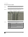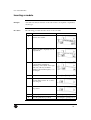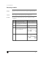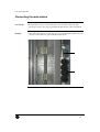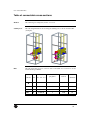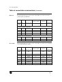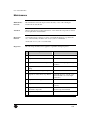
1
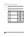
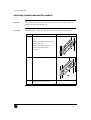
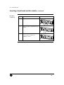
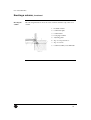
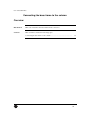
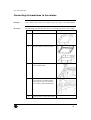
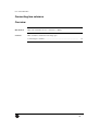
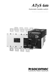
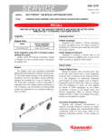
GE Consumer & Industrial
Power Protection
SEN Plus
Pan-European metalclad
Low voltage system
The heart of your business
User Manual
Rev. 00-141106
User manual SEN Plus
Table of Contents
Table of Contents................................................................................................................... 1
Overview................................................................................................................................ 4
CONTROL CENTRE WITH PLUG-IN MODULES...................................................... 5
Overview................................................................................................................................ 5
Introduction.................................................................................................................. 6
Overview................................................................................................................................ 6
Introduction............................................................................................................................ 7
General characteristics ................................................................................................ 8
Overview................................................................................................................................ 8
Functional segments of the column........................................................................................ 9
Main components of a motor starter application .................................................................. 10
Main components of a fused load break switch module....................................................... 11
Opening a door ...........................................................................................................13
Overview.............................................................................................................................. 13
Opening the door of a module.............................................................................................. 14
Opening the door of a load break switch module................................................................. 15
Inserting/removing a module ......................................................................................16
Overview.............................................................................................................................. 16
Inserting a module................................................................................................................ 17
Locking the module in the compartment.............................................................................. 18
Inserting a load break switch module................................................................................... 19
Locking the load break switch module in the compartment................................................. 21
Removing a module ............................................................................................................. 22
Removing a load break switch module ................................................................................ 23
Connecting a module...................................................................................................25
Overview.............................................................................................................................. 25
Removing the bottom plate (for small modules) .................................................................. 26
Connecting the main cables ................................................................................................. 27
Connecting the auxiliary cables ........................................................................................... 28
Inserting the bottom plate .................................................................................................... 29
Replacing a compartment door ...................................................................................30
Overview.............................................................................................................................. 30
Replacing a compartment door ............................................................................................ 31
Disconnecting cables from the compartment door ............................................................... 32
Mounting a compartment door............................................................................................. 33
Removing the IP20 shroud from the vertical busbar...................................................35
Overview.............................................................................................................................. 35
Removing the IP20 shroud from the vertical busbar ............................................................ 36
Change module arrangement ......................................................................................37
Overview.............................................................................................................................. 37
Example: replacing 2 modules size 5E by 1 module size 10E ............................................. 38
User manual SEN Plus
CONTROL CENTRE WITH WITHDRAWABLE MODULES...................................39
Overview.............................................................................................................................. 39
Introduction.................................................................................................................40
Overview.............................................................................................................................. 40
Introduction.......................................................................................................................... 41
General characteristics ...............................................................................................42
Overview.............................................................................................................................. 42
Functional segments of the column...................................................................................... 43
Functional parts of the module............................................................................................. 43
Plugs types. .......................................................................................................................... 45
Main components of a motor starter application ................................................................. 46
Overview.............................................................................................................................. 47
Operating the worm gear...................................................................................................... 48
Operating positions of the withdrawable module................................................................ 48
Operating positions of the withdrawable module................................................................. 49
Opening a door..................................................................................................................... 50
Overview.............................................................................................................................. 50
Opening the door of a module.............................................................................................. 51
Inserting/removing a module ......................................................................................52
Overview.............................................................................................................................. 52
Inserting a module................................................................................................................ 53
Locking/Unlocking the module in the compartment ............................................................ 54
Removing a module ............................................................................................................. 55
Connecting a module...................................................................................................56
Overview.............................................................................................................................. 56
Connecting the main cables ................................................................................................. 57
Connecting the main cables in cubicles with separation form 4b type 7.............................. 58
Connecting the control cables .............................................................................................. 61
Inserting the bottom plate .................................................................................................... 62
Removing 24-pole auxiliary control plug. ........................................................................... 63
Removing the vertical separation between the cable and equipment compartment.............. 64
Mounting the outgoing plug in the column. ......................................................................... 65
Change module arrangement ......................................................................................66
Overview.............................................................................................................................. 66
Example: replacing 2 modules size 5E by 1 module size 10E ............................................. 67
User manual SEN Plus
POWER CENTRE.............................................................................................................68
Overview.............................................................................................................................. 68
Introduction.................................................................................................................69
Overview.............................................................................................................................. 69
Introduction.......................................................................................................................... 70
General characteristics ...............................................................................................71
Overview.............................................................................................................................. 71
Functional segments of the column...................................................................................... 72
INSTALLATION OF A COLUMN .................................................................................75
Overview.............................................................................................................................. 75
Storage of columns......................................................................................................76
Overview.............................................................................................................................. 76
Storage of columns .............................................................................................................. 77
Transport of a column.................................................................................................78
Overview.............................................................................................................................. 78
Transport of a column .......................................................................................................... 79
Erecting the column ....................................................................................................81
Overview.............................................................................................................................. 81
Erecting a column ................................................................................................................ 82
Connecting the base frame to the column ...................................................................84
Overview.............................................................................................................................. 84
Connecting the baseframe to the column ............................................................................. 85
Connecting two columns...................................................................................................... 86
Overview.............................................................................................................................. 86
Connecting two columns...................................................................................................... 87
Connecting the main busbar system............................................................................88
Overview.............................................................................................................................. 88
Connecting the main busbar system..................................................................................... 89
Torque values..............................................................................................................91
Overview.............................................................................................................................. 91
Torque values for mechanical connections .......................................................................... 92
Torque values for electrical connections.............................................................................. 94
Cable connection in columns with two breakers.........................................................95
Overview.............................................................................................................................. 95
Arrangement of external connections..........................................................................97
Overview.............................................................................................................................. 97
Table of connectable cross-sections..................................................................................... 98
Final testing ..............................................................................................................100
Overview............................................................................................................................ 100
Final testing........................................................................................................................ 101
MAINTENANCE.............................................................................................................102
Overview............................................................................................................................ 102
Maintenance....................................................................................................................... 103
User manual SEN Plus
User Manual
Overview
Introduction
This document describes the operation and maintenance of the SEN Plus. Read this
book before taking the column into operation to ensure correct handling, operation
and proper maintenance from the beginning. Keep this book available for the
operator(s).
Contents
This document contains the following topics.
Control Centre with plug-in modules...........................................................
5
Control Centre with withdrawable modules ...............................................
39
Power Centre ..................................................................................................
68
Installation of a column .................................................................................
75
Maintenance ...................................................................................................
102
4
User manual SEN Plus
Control Centre with plug-in modules
Overview
Introduction
This chapter discusses the Control Centre and its correct use.
Contents
This document contains the following topics.
Introduction....................................................................................................
6
General characteristics ..................................................................................
8
Opening a door ...............................................................................................
13
Inserting/removing a module ........................................................................
16
Connecting an application.............................................................................
25
Replacing a compartment door.....................................................................
30
Removing the IP20 shroud from the vertical busbar..................................
35
Change module arrangement........................................................................
37
5
User manual SEN Plus
Introduction
Overview
Introduction
This chapter discusses briefly the general principle of the Control Centre.
Contents
This document contains the following topics.
Introduction......................................................................................................
7
6
User manual SEN Plus
Introduction
Principle
The Control Centre is subdivided in three functional zones:
• Busbar zone
• Equipment zone
• Cable zone
Busbar zone
The busbar zone is located at the rear of the column and contains the main
horizontal and vertical busbar system. Internal separation sheets are dividing the
busbar zone from the equipment and cable zone and are protecting the operator
against accidental contact with hazardous life parts.
Equipment zone The standard equipment zone, is separated from the cable zone by means of the
individual sides of the module installed. Additional separation sheets can be
provided to segregate the equipment zone from the cable zone in the event of
uninstalled modules.
Cable zone
The cable zone is designed for fast and comfortable cabling.
7
User manual SEN Plus
General characteristics
Overview
Introduction
This section discusses briefly the main segments of the column and the main
segments of the modules.
Contents
This document contains the following topics.
Functional segments of the column..................................................................
9
Main components of a motor starter application.............................................
10
Main components of a fused load break switch module ..................................
11
8
User manual SEN Plus
Functional segments of the column
Principle
The column is subdivided in three functional zones.
Illustration
The following illustration shows the three functional zones of a Control Centre.
Busbar zone
Equipment
zone
Cable zone
9
User manual SEN Plus
Main components of a motor starter application
Illustration
The following illustration shows the main components of the motor starter
application.
2
1
3
4
5
6
7
Components
The following table gives an overview of the main components of a motor starter
application.
Part
Function
1
Incoming plug (line side)
2
18 pole plug (optional for door-wiring)
3
Main breaker
4
Contactor
5
Frame
6
Cable entry for main outgoing cables
7
16 pole plug (control plug)
10
User manual SEN Plus
Main components of a fused load break switch module
Illustration
The following illustrations show the main components of a load break switch
module.
1
2
3
Continued on next page
11
User manual SEN Plus
Main components of a fused load break switch module,
Continued
Illustration
(continued)
4
Components
5
The following table gives a survey of the main components of a load break switch
module.
Part
Function
1
load break switch module
2
Handle
3
Door
4
16 pole plug (option)
5
Incoming stabs
12
User manual SEN Plus
Opening a door
Overview
Introduction
This section describes how to open the door of the different modules.
Warning!
The operator must apply all relevant safety precautions including those mentioned
in this book. Take all precautions to prevent accidental contact with hazardous live
parts. Before carrying out any adjustments, maintenance or repair, switch off the
voltage of the affected module(s).
Contents
This document contains the following topics.
Opening the door of a module..........................................................................
14
Opening the door of a load break switch module.............................................
15
13
User manual SEN Plus
Opening the door of a module
Principle
The door of a module which is provided with a main power switch can only be
opened if the main power switch is turned off.
Illustration
The following illustration shows the main power switch and door lock.
Main power switch
Procedure
Door lock
The following procedure describes the opening of the door.
Step
Action
1
Turn off the module’s main power switch (if provided).
2
Unlock the door lock of the module.
3
Open the door.
14
User manual SEN Plus
Opening the door of a load break switch module
Principle
The door is locked by means of the main power switch and a door lock.
Illustration
The following illustration shows the switches for opening the door.
Main power
switch
Procedure
Door lock
(double bearded)
The following procedure describes the opening of the door.
Step
Action
Illustration
1
Turn off the main power switch of _
the afected module.
2
Open the double-bearded lock(s).
3
Simultaneously pull and turn the
main power switch.
4
Open the door.
_
_
15
User manual SEN Plus
Inserting/removing a module
Overview
Introduction
This section describes how to insert and remove the modules.
Warning!
The operator must apply all relevant safety precautions including those mentioned
in this book. Take all precautions to prevent accidental contact with hazardous live
parts. Before carrying out any adjustments, maintenance or repair, switch off the
voltage of the affected module(s).
Contents
This document contains the following topics.
Inserting a module............................................................................................
17
Locking the module in the compartment..........................................................
18
Inserting a load break switch module...............................................................
19
Locking the load break switch module in the compartment ............................
21
Removing a module .........................................................................................
22
Removing a load break switch module ............................................................
23
16
User manual SEN Plus
Inserting a module
Principle
A module can easily be inserted or removed in order to be repaired or replaced by
another type.
Procedure
The following procedure describes how to insert a module.
Step
Action
1
Slide the module above the bottom
plate into the column.
2
Push the module completely into the
compartment.
3
Make sure that the module is
positioned in its furthermost
backward position.
Illustration
17
User manual SEN Plus
Locking the module in the compartment
Principle
The module is locked on both sides by two tongues through the bottom plate and
the guides.
Procedure
The following procedure describes how to lock a module in a column
compartment.
Step
Action
1
Loosen the screws on the module.
2
Slide the screws completely down so
that the tongues are positioned
through the cut-out.
3
Tighten the screws again.
Illustration
18
User manual SEN Plus
Inserting a load break switch module
Principle
The load break switch modules can easily be inserted or removed in order to be
repaired or replaced by another type.
Procedure
The following procedure describes how to insert a load break switch module.
Step
1
Action
Illustration
Mount the connector guide.
Note:
1) Make sure that the pins are in the
vertical frame part.
2) Make sure that the spacer is
between the profile and the
connector.
2
Fix the connector guide.
3
Repeat step one and two for installing _
the guide on the opposite site.
Continued on next page
19
User manual SEN Plus
Inserting a load break switch module, Continued
Procedure
(continued)
Step
Action
4
Slide the module into the column.
5
Push the module completely into the
column.
6
Make sure that the module is
positioned in its furthermost
backward position.
Illustration
20
User manual SEN Plus
Locking the load break switch module in the compartment
Principle
The module is locked on both sides by four locking bolts.
Illustration
The following illustration shows the position of the four locking bolts.
21
User manual SEN Plus
Removing a module
Principle
A module can easily be removed in order to be repaired or replaced by another
type.
Attention
Always disconnect the power before disconnecting power supply cables.
Procedure
The following procedure describes how to remove a module from a column
compartment.
Step
Action
Illustration
1
Open the door.
See “Opening the door of a
module”
2
Loosen the mounting screws of the
18 pole plug for door wiring and the
16 pole “side” plug.
3
Disconnect the plugs.
4
Disconnect the main cables from the
module.
See “Connecting the main
cables”
5
Loosen the modules mounting
screws.
See “Removing the bottom
plate ”
6
Take the module by the front plates.
7
Pull the module out of the column.
22
User manual SEN Plus
Removing a load break switch module
Principle
The motor load break switch module can easily be removed in order to be
replaced.
Special tool
The following illustration shows the special tool required for pulling out the
module.
Procedure
The following procedure describes how to remove a load break switch module
from a column compartment.
Step
Action
Illustration
1
Open the door.
See “Opening the door of a
load break switch module”
2
Disconnect the power supply from
the module.
_
3
Screw the four mounting screws
loose.
Continued on next page
23
User manual SEN Plus
Removing a load break switch module, Continued
Procedure
(continued)
Step
Action
3
Shove the special extraction tool over
the pin of the door switch.
4
Pull the module out of the column.
Illustration
24
User manual SEN Plus
Connecting a module
Overview
Introduction
This section describes how to connect the modules.
Warning!
The operator must apply all relevant safety precautions including those mentioned
in this book. Take all precautions to prevent accidental contact with hazardous live
parts. Before carrying out any adjustments, maintenance or repair, switch off the
voltage of the affected module(s).
Contents
This document contains the following topics.
Removing the bottom plate (for small modules)..............................................
26
Connecting the main cables .............................................................................
27
Connecting the auxiliary cables .......................................................................
28
Inserting the bottom plate.................................................................................
29
25
User manual SEN Plus
Removing the bottom plate (for small modules)
Principle
The module must be unlocked from the bottom plate in order to remove the plate.
Procedure
The following procedure describes how to remove the bottom plate.
Step
Action
1
Loosen the modules mounting
screw.
2
Slide the screw upwards.
3
Tighten the screw.
4
Repeat step 1 to 3 for the other
screw.
5
Extract the bottom plate.
Illustration
_
26
User manual SEN Plus
Connecting the main cables
General rule
The main cables are connected directly to the electrical component.
Remark
The connection of external cables is easier when the bottom plate is removed.
Example
• The main cables must be connected to the last electrical component for a motor
starter application.
• The main cables must be connected directly to the circuit breaker (place
indicated by the arrow) for a feeder application.
Available after
preparing the
sample for
Hanover fair.
27
User manual SEN Plus
Connecting the auxiliary cables
General rule
The auxiliary cables are connected by means of a 16 pole plug at the side of the
module (see “main components of a module”). The plug-in is secured by means of
two bolts.
Illustration
The following illustration shows the securing of the plug-in.
28
User manual SEN Plus
Inserting the bottom plate
Principle
Always insert the bottom plate to make a separation between the different
modules.
Procedure
The following procedure describes how to insert the bottom plate.
Step
Action
1
Slide the plate into the column
in such a way that the borders of
the plate are between the guides
of the column.
2
Push the plate forward between
the conduits until the tongues are
through the cut-outs.
3
Make sure that the plate is
positioned in its furthermost
backward position.
Illustration
_
29
User manual SEN Plus
Replacing a compartment door
Overview
Introduction
This section describes how to replace a compartment door.
Warning!
The operator must apply all relevant safety precautions including those mentioned
in this book. Take all precautions to prevent accidental contact with hazardous live
parts. Before carrying out any adjustments, maintenance or repair, switch off the
voltage of the affected module(s).
Contents
This document contains the following topics.
Replacing a compartment door ........................................................................
31
Disconnecting cables from the compartment door...........................................
32
Mounting a compartment door.........................................................................
33
30
User manual SEN Plus
Replacing a compartment door
Principle
A compartment door can easily be replaced by another.
Procedure
The following procedure describes how to replace a compartment door.
Step
Action
Illustration
1
Open the door.
See “Opening the door of a
module”
2
Disconnect the plug-in module.
See “Disconnecting cables
from the compartment door”
3
Remove the circlips.
4
Pull out the pin.
5
Unhitch the compartment door.
6
Mount the new compartment door.
See “Mounting a compartment
door”
31
User manual SEN Plus
Disconnecting cables from the compartment door
Principle
The cables from the compartment door (for indicator lamps, controls, etc.) are
connected with the module by means of a 18 pole plug.
Illustration
The following illustration is showing the position of the plug.
18 pole
plug
Procedure
The following procedure describes how to disconnect the plug.
Step
Action
1
Loosen the 2 tightening screws
from the 18 pole.
2
Pull out the plug from the socket.
Illustration
32
User manual SEN Plus
Mounting a compartment door
Principle
The different types of doors can easily be installed on the column.
Procedure
The following procedure describes the mounting of a compartment door.
Step
Action
1
Are the hinge brackets correctly
positioned according to the height
of the door?
• When yes, go to step 3.
Illustration
X = X
• When no, go to step 2.
2
Reposition or mount a hinge
bracket so that the door can be
positioned between the two
brackets.
3
Mount the door over the pin of the
bottom bracket.
Continued on next page
33
User manual SEN Plus
Mounting a compartment door, Continued
Procedure
(continued)
Step
Action
4
Shove the pin in the upper hinge.
5
Mount the circlips.
Illustration
34
User manual SEN Plus
Removing the IP20 shroud from the vertical busbar
Overview
Introduction
This section describes how to remove the protective IP20 shroud from the busbar.
Warning!
The operator must apply all relevant safety precautions including those mentioned
in this book. Take all precautions to prevent accidental contact with hazardous live
parts (busbars in the back!). Before carrying out any adjustments switch off the
voltage.
Contents
This document contains the following topics.
Removing the IP20 shroud from the vertical busbar........................................
36
35
User manual SEN Plus
Removing the IP20 shroud from the vertical busbar
Principle
The vertical busbars is protected against direct contact by means of a IP20 shroud.
If necessary (e.g. for maintenance) the shrouds can be removed as described
below.
Procedure
The following procedure describes how to remove the IP20 shroud.
Step
Action
1
Unlock the 2 latching tongues
from the frame while pulling the
shroud from the busbars.
Illustration
36
User manual SEN Plus
Change module arrangement
Overview
Introduction
Modules can have different sizes. The column arrangement can easily be adjusted
for installing another size.
Warning!
The operator must apply all relevant safety precautions including those mentioned
in this book. Take all precautions to prevent accidental contact with hazardous live
parts. Before carrying out any adjustments, maintenance or repair, switch off the
voltage of the affected module(s).
Contents
This document contains the following topics.
Example: replacing 2 modules size 5E by 1 module size 10E.........................
38
37
User manual SEN Plus
Example: replacing 2 modules size 5E by 1 module size
10E
Principle
The compartment of a module can easily be adjusted to contain a module of
another size.
Procedure
The following procedure describes how to replace 2 modules size 5E by 1 module
size 10E.
Step
Action
Instruction
1
Open the door of the 2 modules size
5E.
“Opening the door of a
module”
2
Remove the bottom plate of the upper “Removing the bottom plate ”
module.
3
Disconnect the cables from the
compartment door.
“Disconnecting cables from the
compartment door”
Attention: If the 16 pole plug is used
this one must also be disconnected.
4
Disconnect the main and auxiliary
cables.
_
5
Remove the 2 modules size 5E.
“Removing a module”
6
Remove the 2 guiders of the upper
module size 5E.
7
Replace the doors by the door of a
10E module.
“Replacing a compartment
door”
8
Insert the 10E module.
“Inserting a module”
9
Connect the 10E module.
“Connecting a module”
38
User manual SEN Plus
Control Centre with withdrawable modules
Overview
Introduction
This chapter discusses the Motor Control Centre and its correct use.
Contents
This document contains the following topics.
Introduction....................................................................................................
40
General characteristics ..................................................................................
42
Worm gear mechanism operation ................................................................
47
Opening a door ...............................................................................................
50
Inserting/removing a module ........................................................................
16
Connecting a module......................................................................................
25
Replacing a compartment door.....................................................................
30
Change module arrangement........................................................................
37
39
User manual SEN Plus
Introduction
Overview
Introduction
This chapter discusses briefly the general principle of the Motor Control Centre.
Contents
This document contains the following topics.
Introduction......................................................................................................
41
40
User manual SEN Plus
Introduction
Principle
The Motor Control Centre is subdivided in three functional zones:
• Busbar zone
• Equipment zone
• Cable zone
Busbar zone
The busbar zone is located at the rear of the column and contains the main
horizontal and vertical busbar system. Internal separation sheets are dividing the
busbar zone from the equipment and cable zone and are protecting the operator
against accidental contact with hazardous parts.
Equipment zone The standard equipment zone, is separated from the cable zone by means of
vertical separation sheets. Additional covers can be provided to close the contact
holes of the auxiliary control terminal in the separation sheet in the event of
uninstalled modules.
Cable zone
The cable zone is designed for fast and comfortable cabling.
41
User manual SEN Plus
General characteristics
Overview
Introduction
This section discusses briefly the main segments of the column and the main
segments of the modules.
Contents
This document contains the following topics.
Functional segments of the column..................................................................
43
Functional parts of the module.........................................................................
43
Plugs types ......................................................................................................
45
Main components of a motor starter application..............................................
46
42
User manual SEN Plus
Functional segments of the column
Principle
The column is subdivided in three functional zones.
Illustration
The following illustration shows the three functional zones of a Control Centre.
Functional parts of the module.
Principle
Notice
The withdrawable modules have incoming, outgoing and control terminals. The
incoming terminal is movable respect the base of the module. The outgoing and
control terminals are fixed to the module. The instrument plate is fixed to the tray.
The operations on the worm gear mechanism are only allowed with closed doors.
43
User manual SEN Plus
Functional segments of the column, continued
Ilustration
Incoming
plug
(moveable)
Worm gear
mechanism
Outgoing
plug
Auxiliary
control
plug
44
User manual SEN Plus
Plugs types.
Principle
The Motor Control Centre has three kinds of plugs:
• Incoming plug
• Outgoing plug
• Auxiliary control plug
Incoming
plug
Outgoing
plug
Auxiliary
control plug
The incoming plug is located at the rear left side of the module and allows the
connection of the main circuit of the tray to vertical busbars.
The outgoing plug is located at the rear right side of the module and allows the
connection of the main circuit of the module to the outgoing plug in the column.
The terminals for cable connection are located in rear of the cable compartment.
The auxiliary control plug is located at the right side of the module and allows the
connection to the female (in the column). The standard plug has 24 pins. An
additional 24-pin auxiliary control plug can be provided if a higher number of pins
is required.
45
User manual SEN Plus
Main components of a motor starter application
Illustration
The following illustration shows the main components of the motor starter
application.
1
2
7
4
8
6
3
5
9
Components
The following table gives an overview of the main components of a motor starter
application.
Part
Function
1
Incoming plug
2
Outgoing plug
3
24 pole aux. control plug
4
Main breaker
5
Contactor
6
Base plate
7
Side walls
8
Mounting plate
9
Worm gear mechanism
46
User manual SEN Plus
Worm gear mechanism operation.
Overview
Introduction
This section discusses briefly the function of the worm gear mechanism and the
terminals positions.
Contents
This document contains the following topics.
Operating the worm gear..................................................................................
48
Operating positions of the withdrawable module ...........................................
49
47
User manual SEN Plus
Operating the worm gear.
Principle
The mechanism to remove the incoming plug is a worm gear which moves a slide
fixed to the incoming terminal. The movement of the worm gear provokes the
movement of the incoming terminal respect the tray base, connect or disconnect
the incoming plug from the vertical busbar.
To move the worm gear, one external “T” tool is required. The access to the worm
gear is protected by a cover, which can be locked with up to 3 padlocks.
Illustration
The following illustration shows how to operate the worm gear..
48
User manual SEN Plus
Operating positions of the withdrawable module
Illustration
The following illustration shows the different positions of the module respect to
the column and terminals positions.
49
User manual SEN Plus
Opening a door
Overview
Introduction
This section describes how to open the door of the different modules.
Warning!
The operator must apply all relevant safety precautions including those mentioned
in this book. Take all precautions to prevent accidental contact with hazardous live
parts. Before carrying out any adjustments, maintenance or repair, switch off the
voltage of the affected module(s).
Contents
This document contains the following topics.
Opening the door of a module..........................................................................
51
50
User manual SEN Plus
Opening the door of a module
Principle
The door of a module that is provided with a main power switch can only be
opened if the main power switch is turned off and the worm gear is in off position.
Illustration
The following illustration shows the main power switch and door lock.
Worm gear
Procedure
Main power switch
Door lock
The following procedure describes the opening of the door.
Step
Action
1
Turn off the module’s main power switch.
2
Remove the padlock from the worm gear cover (if provided).
3
Using the T-tool turn the worm gear to the OFF position.
4
Unlock the door lock of the module.
5
Open the door.
51
User manual SEN Plus
Inserting/removing a module
Overview
Introduction
This section describes how to insert and remove the modules.
Warning!
The operator must apply all relevant safety precautions including those mentioned
in this book. Take all precautions to prevent accidental contact with hazardous live
parts. Before carrying out any adjustments, maintenance or repair, switch off the
voltage of the affected module(s).
Contents
This document contains the following topics.
Inserting a module............................................................................................
53
Locking the module in the compartment..........................................................
54
Removing a module .........................................................................................
55
52
User manual SEN Plus
Inserting a module
Principle
A module can easily be inserted or removed in order to be repaired or replaced by
another type.
Procedure
The following procedure describes how to insert a module.
Step
Action
Illustration
1
Slide the module above the bottom
plate into the column.
2
Push the module completely into the
compartment.
3
Make sure that the module is
positioned in its furthermost
backward position (latch on the right
hand side of the tray should be
parallel to the instrument plate) - see
next chapter
4
Close the door.
5
Open the plastic cover of the module
interlock and insert the “T” tool into
the worm gear.
6
Turn the “T” tool clockwise until the
ON position.
7
Close the plastic cover.
- See chapter “opening a door”
8
Close the padlock (if provided)
- See chapter “opening a door”
See chapter “opening a door”
53
User manual SEN Plus
Locking/Unlocking the module in the compartment
Principle
The module is locked on one side by one latch through the bottom plate.
Procedure
The following procedure describes how to lock and unlock a module in a column
compartment.
Step
Action
1
Slide the module slowly above the
bottom plate into the column until it
reaches the furthermost backward
position - the latch on the right hand
side of the module snaps into the
second cut-out of the bottom plate –
the module is in standby position.
2
Make sure that the module is
positioned in its furthermost
backward position - the latch that is
situated at the right hand side of the
tray should be parallel to the
instrument plate.
3
To move the module to disconnected
(isolated) position pull the latch
towards yourself and pull the module
towards yourself until the latch snaps
into the first cut-out of bottom plate.
4
To remove the module out of the
column pull the latch toward yourself
and then pull toward yourself until
the module is drawn out of column.
Illustration
54
User manual SEN Plus
Removing a module
Principle
A module can easily be removed in order to be repaired or replaced by another
type.
Attention
Before opening doors assure that the worm gear is in OFF position.
Procedure
The following procedure describes how to remove a module from a column
compartment.
Step
Action
Illustration
1
Unlock padlock (if accessible).
See chapter “opening a door”
2
Insert the “T” tool to worm gear and
turn to the OFF position. Afterwards
take out the tool.
See “Mechanism position”
3
Open the door.
See “Opening the door of a
module”
4
Take the module by left hand at the
left of the worm gear, and the right
hand in the blocking part.
5
Pull the module out of the column.
55
User manual SEN Plus
Connecting a module
Overview
Introduction
This section describes how to connect the modules.
Warning!
The operator must apply all relevant safety precautions including those mentioned
in this book. Take all precautions to prevent accidental contact with hazardous live
parts. Before carrying out any adjustments, maintenance or repair, switch off the
voltage of the affected module(s).
Contents
This document contains the following topics.
Connecting the main cables .............................................................................
57
Connecting the main cables in cubicles with separation form 4b type 7 ........
58
Connecting the auxiliary cables .......................................................................
61
Inserting the bottom plate.................................................................................
62
Removing the 24-pole auxiliary control plug. ................................................
63
Removing the vertical separation between the cable compartment and
equipment compartment...................................................................................
64
Mounting the outgoing plug in the column......................................................
65
56
User manual SEN Plus
Connecting the main cables
General rule
The main cables are not connected directly to the electrical component. The
connection is made to the outgoing terminals mounted in the cable compartment.
Example
• The main cables must be connected to the outgoing terminals situated in the rear
left side of the cable zone (place indicated by the arrow).
57
User manual SEN Plus
Connecting the main cables in cubicles with separation
form 4b type 7
General rule
The connection of the main cables of each functional unit is made to the outgoing
terminals mounted in the cable compartment that are additionally separated from
other cable connections by rigid barriers out of sheet-metal.
Example
• The main cables must be connected to the outgoing terminals situated in the rear
left side of the cable zone (place indicated by the arrow) through the cut-outs in
the metal barriers.
58
User manual SEN Plus
Connecting the main cables in cubicles with separation
form 4b type 7, Continued
Procedure
The following procedure describes how to connect the cables in cubicles with
separation form 4b type 7.
Step
Action
1
Unscrew the bolts on one side
cover of the separation box .
2
Unscrew the bolts on the second
side cover of the separation box.
3
Make a hole (holes) in a side
separation cover, and pull
through the cable (cables).
Illustration
59
User manual SEN Plus
Connecting the main cables in cubicles with separation
form 4b type 7, Continued
Step
Action
4
Connect the cables to the clamps
of the outgoing terminal and
screw the side cover to the
construction.
5
Screw the second side cover of
the separation box
6
Repeat steps 1-5 to the other
separation boxes.
Illustration
-
60
User manual SEN Plus
Connecting the control cables
General rule
The control cables are connected by means of a 24-pole plug mounted at the side
of the module (see ”main components of the module”) and the 24-pole socket
mounted in the vertical separation.
Illustration
The following illustration shows the cable connection to the auxiliary control
terminal.
61
User manual SEN Plus
Inserting the bottom plate
Principle
Always insert the bottom plate to make a separation between the different
modules.
Procedure
The following procedure describes how to insert the bottom plate.
Step
Action
1
Slide the plate into the column
in such a way that the borders of
the plate are between the guides
of the column.
2
Push the plate forward between
the conduits until the tongues are
through the cutouts.
3
Make sure that the plate is
positioned in its furthermost
backward position and screw it
with the guides.
Illustration
62
User manual SEN Plus
Removing 24-pole auxiliary control plug.
Principle
Procedure
The 24-pole plug can be removed if the relevant module is removed and all the
control cables are disconnected.
The following procedure describes how to remove the 24-pole aux. control plug.
Step
Action
Illustration
1
Remove the relevant module.
See “Removing a module”
2
Open the cable compartment
door.
-
2
Disconnect the control cables.
See “Connecting the control cables”
3
Screw the two mounting screws
loose.
63
User manual SEN Plus
Removing the vertical separation between the cable and
equipment compartment.
Principle
The vertical separation between the cable compartment and the equipment
compartment is required to achieve the degree of protection of IP 2X.
Procedure
The following procedure describes how to remove the vertical separation.
Step
Action
Illustration
1
Open the cable compartment
door.
-
2
Remove the 24 pole aux. control See “Removing the 24 pole aux.
plug
control plug”
3
Screw the four mounting screws
loose.
64
User manual SEN Plus
Mounting the outgoing plug in the column.
Principle
The outgoing plug in cable compartment can be easily inserted or removed in order
to be repaired or replaced by another type..
Procedure
The following procedure describes how to mount the outgoing plug.
Step
Action
1
Mount the support for the
outgoing plug.
2
Mount the outgoing plug.
Illustration
Note: Make sure that the pins
are in the vertical part frame.
3
Fix the outgoing plug.
65
User manual SEN Plus
Change module arrangement
Overview
Introduction
Modules can have different sizes. The column arrangement can easily be adjusted
for installing another size.
Warning!
The operator must apply all relevant safety precautions including those mentioned
in this book. Take all precautions to prevent accidental contact with hazardous live
parts. Before carrying out any adjustments, maintenance or repair, switch off the
voltage of the affected module(s).
Contents
This document contains the following topics.
Example: replacing 2 modules size 5E by 1 module size 10E.........................
67
66
User manual SEN Plus
Example: replacing 2 modules size 5E by 1 module size
10E
Principle
The compartment of a module can easily be adjusted to contain a module of
another size.
Procedure
The following procedure describes how to replace 2 modules size 5E by 1 module
size 10E.
Step
Action
Instruction
1
Open the door of the 2 modules size
5E.
See “Opening the door of a
module”
2
Remove the 2 modules size 5E.
See “Removing a module”
3
Remove the bottom plate of the upper See “Removing the bottom
module.
plate ”
4
Open the cable compartment door.
5
Disconnect the main and control
cables.
See “Connecting control cables
“ and “Connecting the main
cables”
6
Remove the auxiliary control plug.
See “Removing the 24-pole
aux. control plug “
7
Remove the cable chanel support (if
necessary)
8
Remove the vertical separation sheet. See “Removing the vertical
separation between the cable
and equipment compartment”
9
Remove the upper module guides.
10
Remove the outgoing plug of upper
module.
11
Cover the opening above the
outgoing plug with a plastic cover.
12
Replace the vertical separation sheet
by the vertical separation of a 10 E
module.
13
Mount the auxiliary control plug.
14
Replace the doors 5E by the door of a See “Replacing a compartment
10E module.
door”
15
Insert the 10E module.
See “Inserting a module”
16
Connect the 10E module.
See “Connecting a module”
-
-
See “Mounting outgoing plug
in the column”
See “Remowing the vertical
separation between the cable
and equipment compartment”
67
User manual SEN Plus
Power Centre
Overview
Introduction
This chapter discusses the general characteristics of the Control Centre.
Contents
This document contains the following topics.
Introduction....................................................................................................
69
General characteristics ..................................................................................
71
68
User manual SEN Plus
Introduction
Overview
Introduction
This chapter discusses briefly the general principle of the Power Centre.
Contents
This document contains the following topics.
Introduction......................................................................................................
70
69
User manual SEN Plus
Introduction
Principle
The Power Centre is subdivided in three functional zones:
• Busbar zone
• Equipment zone
• Cable zone
Busbar zone
The busbar zone is located at the rear of the column and contains the main
horizontal and vertical busbar system. Internal separation sheets divide the busbar
zone from the equipment zone and protect the operator against accidental contact
with hazardous live parts. Additional separation sheets can be provided to
segregate the equipment zone from the cable zone.
Cable zone
The cable zone is designed for fast and comfortable cabling.
70
User manual SEN Plus
General characteristics
Overview
Introduction
This section discusses briefly the main segments of the column.
Contents
This document contains the following topics.
Functional segments of the column..................................................................
72
71
User manual SEN Plus
Functional segments of the column
Principle
The column is subdivided in three functional zones.
Illustration
The following illustrations show the three functional zones of a Power Centre:
- the incomer with air circuit breaker type M-Pact,
1
2a
2b
3
Continued on next page
72
User manual SEN Plus
Functional segments of the column, Continued
Illustration
- the outgoing feeder with moulded case circuit breakers type Record Plus.
2a
1
2b
2a
2b
3
Continued on next page
73
User manual SEN Plus
Functional segments of the column, Continued
Components
The following table gives an overview survey of the main components of a Power
Centre.
Part
Function
1
Busbar zone
2a
Equipment zone
2b
Equipment zone
3
Cable zone
74
User manual SEN Plus
Installation of a column
Overview
Introduction
This section describes the correct handling of columns.
Warning!
The operator must apply all relevant safety precautions including those mentioned
in this book. Take all precautions to prevent accidental contact with hazardous live
parts.
Contents
This document contains the following topics.
Storage of columns .........................................................................................
76
Transport of columns.....................................................................................
78
Erecting columns............................................................................................
81
Connecting the base frame to the column ....................................................
81
Connecting two columns................................................................................
84
Connecting the main busbar system.............................................................
88
Torque values .................................................................................................
91
Cable connection in columns with two breakers .........................................
91
Arrangement of external connections ..........................................................
95
Final testing ....................................................................................................
100
75
User manual SEN Plus
Storage of columns
Overview
Introduction
This section describes the factors that must be taken into account for storing a
column.
Contents
This document contains the following topics.
Storage of columns...........................................................................................
77
76
User manual SEN Plus
Storage of columns
Principle
To protect the column during storing certain factors must be taken into account.
Storing place
The switchboards must be stored in dry, ventilated rooms.
Ambient
temperature
-20 °C to +55 °C (short term up to +70 °C, not longer then 24h)
Damaged
packaging
Any damaged packaging shall be renewed in order to protect the assembly against
harmful pollution during storage.
Relative
humidity of the
atmosphere
65 % max
77
User manual SEN Plus
Transport of a column
Overview
Introduction
This section describes the correct way to transport a column.
Contents
This document contains the following topics.
Transport of a column ......................................................................................
79
78
User manual SEN Plus
Transport of a column
How to move a
section?
A vertical section is be moved in an upright position. The section can hang or
stand.
Transport
Use a crane or fork-lift truck for transport.
Limitations
The following table describes the limitations that should be taken into account for
transport.
Single switchboards
Transport sections of Power
Centres with busbar crosssections 2x100x10 and higher
Other transport sections
Measures for
transporting a
Control Centre
Max. width
Max. weight
---
1000 kg
1,5 m
---
2m
2000 kg
The following measures must be followed for transporting a Control Centre.
• Modules for motor Control Centres remain inside the column during transport.
• The plug-in modules shall be interlocked (see ”locking the module in the
compartment”).
• The withdrawable modules shall be interlocked and the worm gear mechanism
should be in ON position (see ”Locking/Unlocking the module in the
compartment” and ”Operating positions of the withdrawable module”)
Measures for
transporting a
Power Centre
The following measures must be followed for transporting a Power Centre with
ACB type M-PACT.
• Circuit breaker type M-PACT frame size 1 remains inside the column during
transport.
• The withdrawable module shall be in “ON” position.
• Circuit breaker frame size 2 shall be shipped seperately.
Continued on next page
79
User manual SEN Plus
Transport of a column, Continued
Preparing for
transport
The following table gives an overview of the preparations for transport.
Step
Action
1
2
Transporting a
column
If the transport is done...
then...
with a fork-lift truck,
the column is bolted on a
(wooden) transport pallet.
with a crane,
the four lifting latches on top
are used with hexagon head
bolts M12x45 St 8.8.
The switchboard is covered on all sides with foil to protect the surface
finish against damage.
The following illustrations show the suggested ways to transport a column.
• By crane
• By fork-lift truck
80
User manual SEN Plus
Erecting the column
Overview
Introduction
This section describes how to erect a column.
Contents
This document contains the following topics.
Erecting a column ............................................................................................
82
81
User manual SEN Plus
Erecting a column
Principle
The column is erected on a well-aligned foundation frame or on a false floor
construction.
Maximum fall
A maximum fall of 2 mm per m column width is acceptable.
Foundation
frame
The following illustration shows the possible components on the foundation frame,
depending on the column depth and arrangement.
1. Only at the end of the
switchboard
2. Only with 600 mm depth
columns back-to-back
arrangement
3. M10 - screw for a foundation
frame
4. Column fish-plate
Continued on next page
82
User manual SEN Plus
Erecting a column, Continued
Erecting the
column
The following illustration shows the erection scheme with the components for a
column.
1. Foundation frame
2. Column fish-plate
3. Column frame
4. Load plug for M10
5. Adjusting plates
6. Top of composition floor
7. Top of concrete
8. Column assembly screw M12x50
83
User manual SEN Plus
Connecting the base frame to the column
Overview
Introduction
This section describes the base frame and its correct use.
Contents
This document contains the following topics.
Connecting the base frame to the column ........................................................
87
84
User manual SEN Plus
Connecting the baseframe to the column
Principle
A base frame can be added to the column to give more space for the final cabling.
Procedure
The following procedure describes how to connect the base frame to the column.
Step
Action
1
Assemble the base frame.
2
Place the column on the base frame.
2a
Put a bushing between the base frame
and the cubicle frame.
2b
Make the connection with a
hexagonal head screw M 12x50 St
8.8 through the cut-outs in the base
frame and the cubicle and the bush.
3
Repeat the step 2 for the other screws
Illustration
-
85
User manual SEN Plus
Connecting two columns
Overview
Introduction
This section describes how to connect two columns.
Contents
This document contains the following topics.
Connecting two columns..................................................................................
87
86
User manual SEN Plus
Connecting two columns
Principle
Several columns can be connected to make one panel.
Procedure
The following procedure describes how to connect two columns.
Step
Action
1
Remove the side panels
2
Screw the M 6 x16 metric bolt from
one side into the hexagonal bolt.
3
Put the two panels next to each other.
Screw the second bolt into the
hexagonal bolt.
Illustration
_
87
User manual SEN Plus
Connecting the main busbar system
Overview
Introduction
This section describes how to connect the busbars of two columns.
Contents
This document contains the following topics.
Connecting the main busbar system.................................................................
89
88
User manual SEN Plus
Connecting the main busbar system
Principle
The busbars of two or more columns can be connected.
Fishplate
Fishplates are used for making the connection. The following illustration gives an
example of such a fishplate.
Position
fishplate
The following illustration shows the position of such a fishplate.
Continued on next page
89
User manual SEN Plus
Connecting the main busbar system, Continued
Procedure
The following procedure describes how to connect the main busbar system.
Step
Action
1
Loosen the fixing screws of the
busbar system without fishplates.
2
Move the columns together. The
fishplate moves between the two
busbar layers.
3
Fix the connection (and column,
see “connecting two columns”)
when the fishplates are in the right
position. Tighten the busbar fixing
screws again.
4
Check torque of fixing elements.
Illustration
_
See “Torque values”
90
User manual SEN Plus
Torque values
Overview
Introduction
This section gives an overview of all torque values for bolt and screw connections
in the column.
Contents
This document contains the following topics.
Torque values for mechanical connections ......................................................
92
Torque values for electrical connections..........................................................
94
91
User manual SEN Plus
Torque values for mechanical connections
Where applied? The torques shall be applied for all mechanical screw joints in SEN Plus.
Property classes The stated values relate to property classes 5.8 to 8.8 for ungreased screws and
nuts.
Deviating
torques
Deviating torques are only admissible if:
• special manufacturer instructions have to be followed.
• special tightening torques are requested in drawings or manufacturing
instructions.
Torques for
hexagon head
bolts
The following table gives a survey of the torques for hexagon head bolts.
Hexagon head bolts
property class 5.8
property class 8.8
Nominal
Minimum
Nominal
Minimum
torques
torques for
torques
torques for
(+10%)
maintenance
(+10%)
maintenance
Nm
Nm
Nm
Nm
< M3
0,4
0,30
0,60
0,50
M3
0,8
0,60
1,10
0,80
M 3,5
1
0,80
1,70
1,50
M4
1,6
1,10
2,50
2,10
M5
3
2,30
5,00
3,80
M6
5,3
3,80
8,50
6,50
M8
12
9,20
20,00
15,00
M 10
26
18,50
41,00
31,00
M 12
41
32,00
70,00
54,00
M 16
100
77
170,00
123
Screw size
Continued on next page
92
User manual SEN Plus
Torque values for mechanical connections, Continued
Torques for
taptite screws
The following table gives a survey of the torques for taptite screws.
Taptite screws
Nominal
Minimum
torques
torques for
(+10%)
maintenance
Nm
Nm
M5
7
2,30
M6
15
3,80
M8
20
9,20
screw size
< M3
M3
M 3,5
M4
M 10
M 12
M 16
Unused
connection
screws
Unused connection screws (e.g. spare installations) have to be tightened with a
tightening torque of 0,2 – 0,3 Nm.
93
User manual SEN Plus
Torque values for electrical connections
Where applied? The torques shall be applied for all electrical screw joints in SEN Plus.
Property classes The stated values relate to property classes 5.8 to 8.8 for screws and nuts that are
not greased.
Deviating
torques
Deviating torques are only admissible if:
• special manufacturer instructions have to be followed.
• special tightening torques are requested in drawings or manufacturing
instructions.
Torques for
Terminals
The following table gives a survey of the torques for electrical terminals.
Terminals general
bolt size
nominal
torques
minimum torques
for maintenance
(+10%)
Unused
connection
screws
N.M.
Nm
< M3
0,5
0,43
M3
1,0
0,70
M 3,5
1,1
0,90
M4
1,5
1,30
M5
3,0
2,50
M6
6,0
4,00
M8
14,0
10,00
M 10
26,0
20,00
M 12
40,0
36,00
M 16
60,0
50,00
Unused connection screws (e.g. for supply or outgoing terminals) have to be
tightened with a tightening torque of 0,2 – 0,3 Nm.
94
User manual SEN Plus
Cable connection in columns with two breakers
Overview
Introduction
This section describes the cable connection in columns with two breakers.
Contents
This document contains the following topics.
Cable connection in column with two breakers ...............................................
103
95
User manual SEN Plus
Cable connection in column with two breakers
Principle
The cable connection in column with two breakers. The N and PE rails are
mounted in the same position like in standard column with one breaker.
Contents
The following illustration shows cable connection in column
96
User manual SEN Plus
Arrangement of external connections
Overview
Introduction
This section contains a table of connectable cross-sections.
Contents
This document contains the following topics.
Table of connectable cross-sections.................................................................
98
97
User manual SEN Plus
Table of connectable cross-sections
Method
The cable lugs are clamped by means of a screw.
Cabling zone
The following illustrations are showing the cabling zone of an air circuit breaker
(examples).
Dilos
The following table gives an overview of the connectable cross-sections for a load
break switch type DILOS.
Rated
Current
Risers
Size
Number of cable
per phase
L1 - L2 - L3
mm
A
Max. crosssection
Bolt
diameter
mm²
mm
1000
6S
60x10
2
240
16
1600
7S
2/50x10
4
240
16
2500
8S
2/80x10
8
240
16
Continued on next page
98
User manual SEN Plus
Table of connectable cross-sections, Continued
M-PACT
The following table gives a survey of the connectable cross-sections for an air
circuit breaker type M-PACT.
Rated
Frame
Current size
Risers
L1- L2 - L3
Number of
cable per phase
mm
A
Max. crosssection
Bolt
diameter
mm²
mm
2
240
16
4
150
12
Connection direct to the riser
1000
1
60x10
1600
1
80x10
4
240
16
2500
1
2/80x10
8
240
16
Connection to auxiliary busbars
Record Plus
3200
2
3/100x10
6 (12)
300
16
4000
2
4/100x10
8 (16)
300
16
The following table gives a survey of the connectable cross-sections for a moulded
case circuit breaker Record Plus
Rated
Frame
Current size
1250
1600
L1- L2 - L3
Number of
cable per phase
mm
A
1000
Risers
K
K
1
Max. crosssection
Bolt
diameter
mm²
mm
40x10
2
240
16
60x10
2
240
16
2/40x10
4
240
16
80x10
4
240
16
2/40x10
4
240
16
80x10
4
240
16
99
User manual SEN Plus
Final testing
Overview
Introduction
This section gives an overview of tests that should be carried out before putting the
assembly into operation.
Contents
This document contains the following topics.
Final testing......................................................................................................
101
100
User manual SEN Plus
Final testing
Principle
Mechanical and electrical function tests should be carried out before putting the
assembly into operation.
Mechanical
function tests
The following mechanical function tests should be carried out before putting the
assembly into operation:
• mechanical function check of electrical components according the relevant
operating instructions
• check all connections to the protective conductor
• check if all barriers and obstacles are in place
• check correct function of the worm gear mechanism
• check correct opening and closing of doors - all doors shall be closed
• check correct function of all door locks
• check interlocking facilities of circuit breakers and doors
• general visual inspection of the assembly.
Electrical
function tests
The following electrical function tests should be carried out before putting the
assembly into operation:
• electrical function check of electrical components according the relevant
operating instructions
• measure the insulation resistance of the assembly
(the insulation resistance of the assembly should not drop below 1 MΩ)
• check all safety equipment as e.g. emergency off
• check the correct function of control-, monitoring- and measuring
instrumentation
• check all control functions.
101
User manual SEN Plus
Maintenance
Overview
Introduction
This section contains a checklist for inspection.
Contents
This document contains the following topics.
Maintenance .....................................................................................................
103
102
User manual SEN Plus
Maintenance
Maintenance
intervals
The maintenance intervals depend on the intensity of use of the switchgear
installed in the switchboard.
Attention
Observe all relevant operating instructions of the electrical components as well as
local requirements and standards.
Inspection
interval
A visual inspection as well as a control of mechanical functions (e.g. interlocks
etc.) of the assembly should be done every 4 years as a minimum.
An interval of <= 1 year is recommended.
Inspection
The following checklist can be applied as a guideline during inspection.
#
inspection
corrective action
1
inspection of service conditions
2
inspection of the assembly
3
inspection of the ventilation openings clean ventilation openings / change
dust filters
4
inspection of measures to achieve IP
rating
5
inspection of cables & glandings
6
inspection on the effects of pollution
7
inspection for damages
8
inspection on the effects of corrosion
repair failures on surface / make dry if
necessary
9
inspection of sub-assemblies &
electrical components
maintenance in accordance with
relevant component manuals
10
inspection of connectors & terminals
clean with dry piece of cloth or use
vacuum cleaner / do not use highpressure air !
Continued on next page
103
User manual SEN Plus
Maintenance, Continued
Inspection
(continued)
#
inspection
corrective action
11
check correct protection of electrical
components & cables
change fuses if necessary
12
check settings of electrical
components ( e.g. overload & short
circuit protection)
correct settings according the
documentation of the electrical
component
13
inspection of plug-in contacts
remove old grease, put new grease on
14
inspection of measures against
check insulation resistance
electrical shock
(PE conductor, PE
connections)
15
check torque values for electrical
connections
(see torque values for electrical
connections)
104
User manual SEN Plus
105