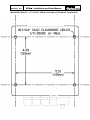
1
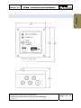
Revision: 3.0 DPM Installation and User Manual DPM DIFFERENTIAL PRESSURE MODULE® EU/IEC: Ex nA op is IIA T5 Gc ( II 3 G) Class 1, Zone 2, 3D (pending) Differential Pressure Switch that Interrupts Refueling in the Event of Monitor Differential Overpressure per JIG Bulletin No. 58. INSTALLATION AND USER GUIDE Parker Hannifin Corporation, Velcon Filtration Division, 1210 Garden of the Gods Road, Colorado Springs, Colorado, 80907, USA www.velcon.com Page 1 of 27 Revision: 3.0 DPM Installation and User Manual 1 ‐ GENERAL WARNING – USER RESPONSIBILITY FAILURE OR IMPROPER SELECTION OR IMPROPER USE OF THE PRODUCTS DESCRIBED HEREIN OR RELATED ITEMS CAN CAUSE DEATH, PERSONAL INJURY AND PROPERTY DAMAGE. This document and other information from Parker‐Hannifin Corporation, its subsidiaries and authorized distributors provide product or system options for further investigation by users having technical expertise. The user, through its own analysis and testing, is solely responsible for making the final selection of the system and components and assuring that all performance, endurance, maintenance, safety and warning requirements of the application are met. The user must analyze all aspects of the application, follow applicable industry standards, and follow the information concerning the product in the current product catalog and in any other materials provided from Parker or its subsidiaries or authorized distributors. To the extent that Parker or its subsidiaries or authorized distributors provide component or system options based upon data or specifications provided by the user, the user is responsible for determining that such data and specifications are suitable and sufficient for all applications and reasonably foreseeable uses of the components or systems. Phone (719) 531‐5855 Toll‐Free (800) 531‐0180 Fax (719) 531‐5690 [email protected] www.velcon.com 2 ‐ INSTALLATION 3 ‐ OPERATION 4 – TROUBLE‐ SHOOTING Parker Hannifin Corporation, Velcon Filtration Division, 1210 Garden of the Gods Road, Colorado Springs, Colorado, 80907, USA www.velcon.com Page 2 of 27 Revision: 3.0 DPM Installation and User Manual TABLE OF CONTENTS 1 GENERAL DESCRIPTION ................................................................................. 4 1.1 1.2 Visual Outputs / Indicators ...................................................................................................... 5 Alarm Triggers ........................................................................................................................ 5 1.2.1 Critical Alarm (Red INDICATOR LIGHT) ..................................................................................... 5 1.2.2 Keyed Reset/Override Momentary Switch .............................................................................. 5 1.3 1.4 1.5 1.6 1.7 1.8 1.9 1.10 1.11 Weight .................................................................................................................................... 5 Safety / Compliance ................................................................................................................ 5 Electrical Input Requirements .................................................................................................. 5 Deadman Switch Relay ............................................................................................................ 6 Mechanical Requirements ....................................................................................................... 6 Overall Dimensions ................................................................................................................. 7 Safety Conventions ................................................................................................................. 8 Operating Precautions ............................................................................................................ 8 Package Contents ................................................................................................................... 9 1.11.1 Inspect shipment .................................................................................................................. 9 1.12 system requirements .............................................................................................................. 10 2 INSTALLATION ............................................................................................. 13 2.1 DPM Module Mounting Instructions ....................................................................................... 13 2.1.1 Tools Needed ......................................................................................................................... 13 2.1.2 Determine Module Installation Location ............................................................................... 13 2.1.3 Drill / Tap Module Mounting Holes ....................................................................................... 16 2.1.4 Prepare and Install the DPM Enclosure ................................................................................. 16 2.1.5 Route Cabling ......................................................................................................................... 17 2.1.6 Determine Proper Power and Sensor Polarity ....................................................................... 18 2.1.8 Make Final Wiring Connections ............................................................................................. 19 2.1.8 Test Functionality ................................................................................................................... 21 2.1.9 System calibration ................................................................................................................. 22 3 OPERATION ................................................................................................. 23 3.2 4 CRITICAL ALERTS .................................................................................................................... 23 TROUBLESHOOTING .................................................................................... 24 Parker Hannifin Corporation, Velcon Filtration Division, 1210 Garden of the Gods Road, Colorado Springs, Colorado, 80907, USA www.velcon.com Page 3 of 27 Revision: 3.0 DPM Installation and User Manual GENERAL DESCRIPTION Velcon’s Differential Pressure Module (DPM) is designed as a simple pressure monitoring system which will halt a fueling operation in the event of monitor/filter differential overpressure as outlined in JIG Bulletin No. 58. The built in Programmable Logic Controller (PLC) receives input from system pressure sensors and activates the vehicle deadman switch in the event that the system differential pressure exceeds 22psid. This indicates that the filters have reached the end of their useful life, or more critically, the filters have become loaded with a contaminant ‘slug’. If the differential pressure exceeds the set limit mandated in the API/EI 1550 specification, the vehicle must be taken out of service and the filters changed. Signal inputs to the DPM can be from variety of devices, to include piston type gages equipped with either a 0‐5V variable or 5V limit signals, two single ended 4‐20mA pressure transducers, one differential 4‐20mA pressure transducer, or one 0‐5V differential pressure transducer. The DPM operates on 12‐ 24 VDC input power to ensure easy installation and safe operation in the intended operating environment. In the event that the 22psid limit is exceeded, the DPM will initiate an alarm sequence, triggering the deadman circuit, thereby automatically disabling the fueling equipment and halting the flow of fuel. Once the filters have been changed and system pressure has returned to normal, a keyed switch is used to reset the system, which will resume normal fueling operation. The DPM is also equipped with a keyed “override” which is used to disable the deadman circuit for purposes of testing full range sensor operation. Note that the DPM module can be easily and quickly upgraded to an FDPM‐MKII – a CORRECTED differential pressure monitoring system. Contact Velcon for further information. USE OF 4‐20Ma PRESSURE SENSORS AND FILTER RUPTURE MONITORING FEATURE In addition to providing inputs from piston type pressure gauges as do other differential pressure monitoring systems currently on the market, Velcon’s DPM will accept 4‐20mA output signals from a variety of standard, off the shelf pressure transducers, in both single ended and differential pressure configurations. Besides lower cost, one advantage to using these types of sensors is that not only will the DPM system shut a fueling dispenser down when system pressure reaches or exceeds 22 psid, but, as an additional safety measure, a ‘watchdog’ feature is also built in to trigger a shutdown in the event of a filter/monitor rupture. This feature takes advantage of a sudden spike followed by a drop in pressure due to a contaminant “slug” which may cause a collapse or rupture in a filter or monitor. Parker Hannifin Corporation, Velcon Filtration Division, 1210 Garden of the Gods Road, Colorado Springs, Colorado, 80907, USA www.velcon.com Page 4 of 27 1 ‐ GENERAL 1 Revision: 3.0 DPM Installation and User Manual The two modes of fuel dispenser shutdown which are built in to the DPM are summarized as follows: SYSTEM OVERPRESSURE ‐ For system overpressure due to filters having reached the end of their useful life, the system pressure must be at or above 22 psid for 3 or more consecutive seconds before a shutdown will occur. This time delay serves to filter out any system pressure bounce or noise that may occur. FILTER/MONITOR RUPTURE ‐ The filter/monitor rupture “watchdog” feature is set up to trigger a shutdown in the event that the differential pressure rises above 50 psid for 0.2 or more seconds. 1.1 VISUAL OUTPUTS / INDICATORS Daylight Readable Red Critical Indicator Daylight Readable Green Power On Indicator 1.2 ALARM TRIGGERS 1.2.1 CRITICAL ALARM (RED INDICATOR LIGHT) 22 psid or 1.5 Bar External Switch Relay (Deadman) 1.2.2 KEYED RESET/OVERRIDE MOMENTARY SWITCH Reset key position is used to unlock the system after pressure returns to normal. This is to be done by a designated supervisor following a filter change‐out once an overpressure condition is encountered. Override key position is used to override the shutdown feature for purposes of system test. See Section 2.1.9. 1.3 WEIGHT 3.55 lbs (1.61 Kg) – DPM Module Only 1.4 SAFETY / COMPLIANCE IP65 NEMA 4X ATEX Directive Class 1, Zone 2, Group 3D EU/IEC: Ex nA op is IIA T5 Gc ( II 3 G) 1.5 ELECTRICAL INPUT REQUIREMENTS Power; 12‐24VDC only, 300mA minimum Pressure input signals; Parker Hannifin Corporation, Velcon Filtration Division, 1210 Garden of the Gods Road, Colorado Springs, Colorado, 80907, USA www.velcon.com Page 5 of 27 1 ‐ GENERAL Revision: 3.0 DPM Installation and User Manual Two single ended 4‐20mA transducers, regardless of pressure range. One differential 4‐20mA transducer, regardless of pressure range. One differential 0‐5V transducer, regardless of pressure range. Piston type gage equipped with a 0‐5V electrical output, regardless of pressure range. Piston type gage equipped with a 5V electrical limit switch calibrated for 22psid. 1 ‐ GENERAL o o o o o 1.6 DEADMAN SWITCH RELAY 8A @ 250VAC, or 5A @ 30VDC max. 1.7 MECHANICAL REQUIREMENTS Mounting plate, preferably out of direct sunlight and weather but not necessary Mounting hole pattern 4.33” (110 mm) X 5.51” (140 mm). See the last page of this manual for the tear‐out scaled template. Parker Hannifin Corporation, Velcon Filtration Division, 1210 Garden of the Gods Road, Colorado Springs, Colorado, 80907, USA www.velcon.com Page 6 of 27 Revision: 3.0 DPM Installation and User Manual 1 ‐ GENERAL 1.8 OVERALL DIMENSIONS Parker Hannifin Corporation, Velcon Filtration Division, 1210 Garden of the Gods Road, Colorado Springs, Colorado, 80907, USA www.velcon.com Page 7 of 27 Revision: 3.0 DPM Installation and User Manual Caution! In this document, this symbol expresses the need for extreme caution when performing the documented procedure. Failure to do so may cause harm to the user or the permanently damage the DPM unit. Important! This symbol expresses an important point or step in a procedure. Stop and read carefully before continuing. 1 ‐ GENERAL 1.9 SAFETY CONVENTIONS Note! This symbol expresses an important point to take note of for future reference. 1.10 OPERATING PRECAUTIONS The DPM has been certified for Class 1, Zone 2, Group 3D operating environments. This implies that only under ABNORMAL circumstances will an explosive mixture of air and fuel vapors and an ignition source exist. If a situation arises that will result in an explosive mixture of air and fuel (vapors) in the DPM’s operating environment, during the installation, or maintenance of the DPM, or at any other time , power to the DPM must be de‐energized to avoid the risk of igniting the potentially explosive atmosphere. It is not the intention of Velcon Filters, LLC, to have the DPM unit operate in conditions where there is a NORMALY occurring explosive mixture of gases, vapors, mists or air/dust mixtures. Fuel Compatibility – The following table lists the compatibility of the DPM with common fuels. Compatible JET‐A1 Compatible JET‐A NOT Compatible JET‐B JP‐8 Compatible Aviation Gasoline (Avgas, Aviation Spirit) NOT Compatible Diesel (all grades) Compatible Motor Gasoline or Petrol NOT Compatible Parker Hannifin Corporation, Velcon Filtration Division, 1210 Garden of the Gods Road, Colorado Springs, Colorado, 80907, USA www.velcon.com Page 8 of 27 Revision: 3.0 DPM Installation and User Manual 1.11 PACKAGE CONTENTS Upon receipt of your DPM unit and before continuing, carefully remove and inspect the contents of the carton for damage or missing components. If any damage is visible, or components are missing from the carton, contact Velcon Filters immediately for disposition. Each DPM unit carton should contain the following core components; Parker Hannifin Corporation, Velcon Filtration Division, 1210 Garden of the Gods Road, Colorado Springs, Colorado, 80907, USA www.velcon.com Page 9 of 27 1 ‐ GENERAL 1.11.1 INSPECT SHIPMENT Revision: 3.0 DPM Installation and User Manual 1 ‐ GENERAL The DPM system should consist of the following core components: 1 DPM Processing Unit 1 Installation and Operation Manual 1 4mm Allen Wrench/Key 1 Cable Gland Plug 1 Reset and Override Key Based on your purchase order, additional optional components may be included with the above core components. These may include: Quantity Description 1 Differential Pressure Transducer 2 Paired Pressure Transducers 1.12 SYSTEM REQUIREMENTS Because the DPM is used as a refueling system monitoring device, it will need the following minimum inputs to operate correctly; 1. Power ‐ Power will be in the form of 12‐24VDC with a minimum of 300mA of current. 2. Pressure Signal ‐ The pressure signal can be taken from a number of various off the shelf pressure transducers on the market today which are capable of outputting a 4‐20mA, 0‐ 5VDC, or a 5VDC limit signal. Note – Each DPM is factory configured for the specific pressure sensors that are intended to be used. This configuration cannot be changed in the field. Therefore, if pressure sensor(s) are to be changed or replaced, they must be replaced with sensors which match the range and output of the original sensors exactly. Velcon can recommend and supply pressure transducers as needed. 3. Deadman Switch – The deadman switch can be wired in series with the DPM module, in either a normally closed (N/C), or normally open (N/O) circuit configuration. The N/C configuration ensures operation integrity in the event of a loose or severed wire connection. Parker Hannifin Corporation, Velcon Filtration Division, 1210 Garden of the Gods Road, Colorado Springs, Colorado, 80907, USA www.velcon.com Page 10 of 27 Revision: 3.0 DPM Installation and User Manual 1 ‐ GENERAL Wiring Schematic with Minimum Required Inputs – For proper operation, power, a deadman switch circuit, and ONLY ONE of the sensor input options are required as shown. NOTE – Either pressure transducers or piston type pressure switches may be used with the DPM, although each DPM is calibrated specifically for the transducers being used. Transducers of a different range MUST NOT be substituted for the transducer range that the DPM was originally calibrated for. This will render the DPM inaccurate. Velcon is available to assist in the selection of these types of instruments that are widely available. Velcon also offers both differential pressure transducers as well as single ended pressure transducers which are easily installed in standard 1/4” NPT fittings available on most fuel dispensing systems. Both of these sensors are available with Class 1, Div. 1, or Class 1, Zone 2, Group 3D (standard) ratings. When selecting pressure transducers, it is important to match them to the fueling systems maximum rated pressure and filter change out pressure. Example: If your refueling system is rated for 15 PSI change out, with a 150 PSI static pressure, you will likely choose a pressure transducer rated for 0‐25 PSI range, with a 150 PSI static pressure rating, which will yield the maximum accuracy for a standard off the shelf pressure transducer. Parker Hannifin Corporation, Velcon Filtration Division, 1210 Garden of the Gods Road, Colorado Springs, Colorado, 80907, USA www.velcon.com Page 11 of 27 Revision: 3.0 DPM Installation and User Manual Velcon P/N 764X001 Differential 4‐20mA Output 0‐25 psid Range ¼” NPTF No Rating Velcon P/N 764X008 Differential 4‐20mA Output 0‐2 Bar Range ¼” NPTF Class 1, Division 1 Rating Velcon P/N 764X021 Single Ended (Two required) 4‐20mA Output 0‐100 psid Range ¼” NPTM Class 1, Division 1 Rating Pressure Transducers Available from Velcon – Differential and Single Ended Transducers, shown here as Class 1, Zone 2, and Class 1, Division 1 Standard Classification Ratings. Parker Hannifin Corporation, Velcon Filtration Division, 1210 Garden of the Gods Road, Colorado Springs, Colorado, 80907, USA www.velcon.com Page 12 of 27 1 ‐ GENERAL If your system is rated for a change out pressure of 15 PSI but you use a transducer with 0‐150 PSI range, some accuracy will be lost with the larger range. Revision: 3.0 DPM Installation and User Manual 2 INSTALLATION 2.1 DPM MODULE MOUNTING INSTRUCTIONS 2.1.1 TOOLS NEEDED 2 ‐ INSTALLATION The following is a list of tools that may be needed for a typical DPM refueling vehicle installation; Drill Drill bits as outlined in 2.1.4 below Taps as outlined in 2.1.4 below Wire strippers/cutters Digital multimeter with DC voltage and mA current functions 2.1.2 DETERMINE MODULE INSTALLATION LOCATION Select an area which best suits the location of the DPM Module, taking into consideration the following criteria; IMPORTANT ‐ Install strictly within regional and local fire codes for installation of equipment on aircraft fueling vehicles. This may require installing the DPM Module within the cab when being installed on a refueling truck. Install preferably out of direct sunlight and weather. Although this is not necessary, following this guideline will help to increase the longevity of the unit. Install in an area which is easily viewed and accessible by operators during a refueling operation. Install in an area which will minimize cable runs, i.e., close to power and pressure sensors. Install in an area which will minimize exposure to fuel spillage. If installing Velcon provided Pressure Sensors, install as near as possible to the inlet and outlet of the filter vessel (see diagram below). If installing Velcon provided Pressure Sensors, install in areas which will minimize the vertical difference between the inlet and outlet of the sensors. The more vertical distance put between the inlet and outlet, the more error that will occur as a result of the additional weight of the column of fuel between the two sensors. Parker Hannifin Corporation, Velcon Filtration Division, 1210 Garden of the Gods Road, Colorado Springs, Colorado, 80907, USA www.velcon.com Page 13 of 27 Revision: 3.0 DPM Installation and User Manual LOW PRESSURE SIDE TO AIRCRAFT (OUTLET) CRITCAL WARNING POWER ON FILTER VESSEL DPM 2 ‐ INSTALLATION RESET OPERATE OVERRIDE TM Velcon Filters, LLC. 1210 Garden of the Gods Rd. Colorado Springs, CO 80907 USA [email protected] www.velcon.com 3 X HIGH PRESSURE SIDE II 3 G Serial #: FROM HYDRANT (INLET) Vessel Configuration with Corresponding Differential Pressure Transducer. LOW PRESSURE SIDE TO AIRCRAFT (OUTLET) CRITCAL WARNING POWER ON FILTER VESSEL RESET OPERATE OVERRIDE DPM TM Velcon Filters, LLC. 1210 Garden of the Gods Rd. Colorado Springs, CO 80907 USA [email protected] www.velcon.com 3 X HIGH PRESSURE SIDE II 3 G Serial #: FROM HYDRANT (INLET) Vessel Configuration with Corresponding Single‐Ended Pressure Transducers. Parker Hannifin Corporation, Velcon Filtration Division, 1210 Garden of the Gods Road, Colorado Springs, Colorado, 80907, USA www.velcon.com Page 14 of 27 Revision: 3.0 DPM Installation and User Manual When using single ended pressure transducers, it is sometimes most convenient to “T” off of the piston gage as shown below. 2 ‐ INSTALLATION DPM Installation using Single Ended Pressure Transducers Coupled into High and Low Pressure Sides of a Piston Type Gauge. Parker Hannifin Corporation, Velcon Filtration Division, 1210 Garden of the Gods Road, Colorado Springs, Colorado, 80907, USA www.velcon.com Page 15 of 27 Revision: 3.0 DPM Installation and User Manual 2.1.3 DRILL / TAP MODULE MOUNTING HOLES Once the installation location has been selected for the DPM Module, mark the location of the mounting holes using the 1:1 template on the back page (example template below). Drill/tap the holes as follows; If it is intended to tap the mounting holes, a typical tap size would be 1/4 ‐ 20 UNC or M6X1. If it is intended to drill through holes, a typical drill size would be 17/64” or 6.6 mm clearance holes. 2 ‐ INSTALLATION 2.1.4 PREPARE AND INSTALL THE DPM ENCLOSURE The mounting holes for the DPM are accessible only from the inside of the enclosure; therefore, the following steps will need to be taken to access them. Disengage the lid of the DPM Module using the 4mm Allen key provided. Once opened, CAREFULLY disconnect the wiring harness connector from the Printed Circuit Board inside the enclosure by gently prying the ends of the connector up using the 4mm Allen key as shown. Do not pull on the wire strip. Parker Hannifin Corporation, Velcon Filtration Division, 1210 Garden of the Gods Road, Colorado Springs, Colorado, 80907, USA www.velcon.com Page 16 of 27 Revision: 3.0 DPM Installation and User Manual 2 ‐ INSTALLATION Once the wiring harness has been disconnected, the DPM lid can be carefully set aside. Using an appropriate socket head cap screw or equivalent, fasten the DPM bottom enclosure to the designated location. A 1/4‐20 X 1.5” long socket head cap screw works well for fastening the enclosure to a 1/8” thick plate. 2.1.5 ROUTE CABLING Once the DPM bottom enclosure has been securely mounted, route and secure cabling from power, pressure sensor(s), and the deadman circuit, to the wiring board in the enclosure. It is best practice to leave a small service loop of cable for each of the inputs at the bottom of the enclosure since there is very little room within the enclosure to store the service loops. Parker Hannifin Corporation, Velcon Filtration Division, 1210 Garden of the Gods Road, Colorado Springs, Colorado, 80907, USA www.velcon.com Page 17 of 27 Revision: 3.0 DPM Installation and User Manual 2 ‐ INSTALLATION 2.1.6 DETERMINE PROPER POWER AND SENSOR POLARITY It is extremely important to ensure that power is off and that all polarity has been verified before attempting to make any wiring connections to the DPM. Reversing polarity on any of these connections may result in unit damage or failure. Follow these guidelines to determine proper polarity for each; INPUT POWER – Red normally designates +V (+12 or +24 volts), while black or green normally designates ground. Determine the polarity of your power cable using a multimeter before attempting to make any connection and mark if needed. PRESSURE SENSOR – 4‐20mA output pressure sensors are normally used in a “Loop” configuration, meaning that they are connected between source power (+V) and signal as in the diagram below. Sensors provided by Velcon (Single Ended or Differential) will always come prewired with a black and red lead which will correspond directly to the wiring terminal colors printed on the wiring board terminal block. If using a pre‐existing pressure sensor, refer to the manufacturer’s pressure sensor manual for proper wiring configuration. Parker Hannifin Corporation, Velcon Filtration Division, 1210 Garden of the Gods Road, Colorado Springs, Colorado, 80907, USA www.velcon.com Page 18 of 27 Revision: 3.0 DPM Installation and User Manual 2 ‐ INSTALLATION Typical Wiring of a 4‐20mA Output Pressure Sensor 2.1.8 MAKE FINAL WIRING CONNECTIONS Once all wiring and polarity has been positively determined, complete the following wiring steps; IMPORTANT – Disengage main power to truck BEFORE attempting to make any wiring connections. Failure to do this may result in unit damage or failure. Route each cable through an appropriate cable gland close to its respective wiring terminal and tighten the cable gland enough to create a seal, but being careful not to crush the cable. Once all cables are routed through the cable glands, loop the excess cables appropriately and make the connections. When connecting wires to the terminal block, ensure that the wire ends are properly twisted so that stray wire strands do not bridge to neighboring terminals. Also, ensure that each wire is properly and fully seated within its respective terminal and tightened securely. For standard installations, VOLTAGE INPUT, DEADMAN RELAY OUT (N/C), and one of DIFF. PRESS., LOW PRESS. and HGH PRESS., +5V DEADMAN IN, or +5V DIFF. PRESS. IN will be used. The RELAY OUTPUT for using a Deadman switch will be described below. Insert cable gland plugs (provided) in any unused cable glands. Parker Hannifin Corporation, Velcon Filtration Division, 1210 Garden of the Gods Road, Colorado Springs, Colorado, 80907, USA www.velcon.com Page 19 of 27 Revision: 3.0 DPM Installation and User Manual 2 ‐ INSTALLATION Wire Connection Board – The input circled in red (PULSE INPUT) is NOT used for DPM installations. NOTE – If one 4‐20mA Differential pressure sensor is being used, connect its wiring terminations to the “DIFF PRESS” terminal block location. If two 4‐20mA Single Ended pressure sensors are being used, connect the High Pressure sensor wiring terminations to the “HIGH PRESS” terminal block location, and the Low Pressure sensor wiring terminations to the “LOW PRESS” terminal block location. If a single 0‐5V Differential pressure sensor is being used including a piston type gage, connect its wiring terminations to “0‐5V PRESS. INPUT”. If a 5V switch type device is being used including a piston type gage, connect its wiring terminations to “+5V DEADMAN INPUT”. The “PULSE INPUT” is not used on the DPM device. Deadman – The Deadman relay of the DPM system is designed to be wired in series (loop configuration) with the existing deadman switch of the refueling vehicle. This Relay Output is a simple open/closed switch, which may be set up in either a Normally Open (N/O) or Normally Closed (N/C) configuration, however, it is highly recommended that it be configured as a Normally Closed configuration. A N/C configuration ensures the integrity of the Deadman circuit so that in the event of a loose or severed wire connection, the fueling operation will be shut down until the circuit is resored. See Section 1.9 for relay voltage and current handling specifications of the deadman relay. Parker Hannifin Corporation, Velcon Filtration Division, 1210 Garden of the Gods Road, Colorado Springs, Colorado, 80907, USA www.velcon.com Page 20 of 27 Revision: 3.0 DPM Installation and User Manual 2 ‐ INSTALLATION Deadman Circuit Connection – An example of a Normally Closed Series or ‘Loop’ Deadman wiring configuration. 2.1.8 TEST FUNCTIONALITY Once the DPM has been properly installed, it can be tested for functionality using the following steps; Engage power to the refueling vehicle and verify that the DPM powers‐up properly. Using a restrictor valve on the outlet side of the fuel filter vessel, flow fuel through the system and slowly increase the differential pressure across the filter vessel by closing the restrictor valve. Verify that the DPM shuts the system flow down when the piston gage reaches 22 psid. If the system is does not shut down at 22 psid, disconnect one terminal wire from the pressure transducer and insert a current meter as shown below. Resume fuel flow as described above and verify that there is current flow (in mA) through the transducer. The exact current (mA) that corresponds to a shutdown of 22 psid will vary greatly depending upon the specific transducer range being used. For example, a transducer rated for 0‐25 psid, and with an output of 4‐20 mA will trip the shutdown relay at approximately 18.05 mA. Contact Velcon for the exact current shutdown point of the sensor(s) being used. OVERRIDE – JIG Bulletin No. 58 requires a system shutdown override feature which allows the full range of the pressure transducers to be tested. The DPM provides this override feature through the key switch. Note that because the key switch has a “momentary” actuator, it must be held in position throughout the testing procedure. To use this feature, create a differential pressure rise as described above while engaging the OVERRIDE key Parker Hannifin Corporation, Velcon Filtration Division, 1210 Garden of the Gods Road, Colorado Springs, Colorado, 80907, USA www.velcon.com Page 21 of 27 Revision: 3.0 DPM Installation and User Manual position. Verify that the pressure transducers rise above the 22 psid trip point by measuring current or voltage output. In the example above, a sensor with a 4‐20 mA output and a 0‐25 psid range will trip the shutdown relay at approximately 18.05mA. Using the SHUTDOWN feature however, the sensors output should bypass the 18.05mA shutdown point with increased pressure, preventing the system from shutting down. 2 ‐ INSTALLATION 2.1.9 SYSTEM CALIBRATION The calibration of system components is as follow; DPM Module – The DPM Module does not require calibration. Differential and Single Ended pressure transducers – One year intervals per manufacturers suggested guidelines. It is the responsibility of the equipment installation, operation, and user personnel to arrange for calibration of this equipment at manufacturer suggested intervals. Velcon assumes no responsibility for equipment calibration. Parker Hannifin Corporation, Velcon Filtration Division, 1210 Garden of the Gods Road, Colorado Springs, Colorado, 80907, USA www.velcon.com Page 22 of 27 Revision: 3.0 DPM Installation and User Manual 3 OPERATION 3.2 CRITICAL ALERTS Alerts Critical Alert overrides When a Critical Alert has been activated, the alert status will remain activated until a supervisor resets the unit using the key switch – even if powering down and repowering the unit. A critical alert can be deactivated ONLY after system pressure drops below 22 psid. Under normal operating conditions, the deadman control is tied to the DPM so that when a Critical condition is encountered, the fueling operation is immediately ceased and a supervisor must be alerted. Parker Hannifin Corporation, Velcon Filtration Division, 1210 Garden of the Gods Road, Colorado Springs, Colorado, 80907, USA www.velcon.com Page 23 of 27 3 ‐ OPERATION The purpose of the DPM is to immediately halt a fueling operation in the event of monitor differential overpressure as outlined in JIG Bulletin No. 58. Therefore, the DPM is pre‐programmed to shut the fueling operation down at 22 psid or above, and lock the system in the shutdown condition until filters are replaced and pressure returns to normal. When a system shutdown occurs, the red indicator on the face of the unit will illuminate. NOTE – The DPM has a built in 4 second delay designed to compensate for sensor output “bounce”. Therefore, the differential pressure must have reached or exceeded a value of 22 psid for a consecutive period of 4 seconds before a Critical Warning and lockout condition will occur. Revision: 3.0 DPM Installation and User Manual 4 TROUBLESHOOTING Problem Unit does not power up. ‐ ‐ ‐ ‐ Critical indicator (Red) will not turn off and deadman will not disengage. ‐ ‐ ‐ Deadman does not shut down flow. ‐ ‐ ‐ Not listed ‐ ‐ The deadman switch is not connected in a proper loop configuration with the DPM’s wire connection board. Deadman wire has come loose or broken off. Pressure transducer(s) not outputting the correct voltage/current. Pressure transducer(s) with a range other than what the DPM was originally calibrated for are being used. Pressure transducer(s) with an output other than what the DPM was originally calibrated for are being used. Contact Velcon Filtration Division Parker Hannifin Corporation, Velcon Filtration Division, 1210 Garden of the Gods Road, Colorado Springs, Colorado, 80907, USA www.velcon.com Recommended Fix Check power to the DPM unit, inspect all wiring and terminal blocks. Check and remedy the condition that is causing the high pressure (22 psid or above) condition. Check all wiring connections to RESET switch. Alert the appropriate supervisor to reset the unit. Verify that the deadman switch is connected in a loop configuration with the wire connection board as shown in Section 2.1.8. Verify that all wiring is sound and that there are no frayed or loose connections. Check the pressure transducer output as shown in Section 2.1.9 and verify that the proper voltage/current is being input to the DPM connection board. Verify that the sensor(s) being used with the unit match the output and pressure range indicated on the label located on the lid of the unit. Toll‐Free (800) 531‐0180 Page 24 of 27 4 – TROUBLE‐ SHOOTING Flow shuts down at a pressure other than 22 psid. Possible Cause Power not connected. Vehicle power not engaged. Wire harness terminal block not plugged in to Wiring Board. Power wire has come loose or broken off from DPM computer module wiring harness. The system differential pressure remains at 22 psid or above. The system has not been reset using the RESET key switch following the systems return to normal pressure. Wire has disengaged from RESET switch. Revision: 3.0 DPM Installation and User Manual Terms and Conditions On Manufactured Products EXCLUSIVE LIMITED WARRANTY THE PRODUCTS SOLD HEREUNDER SHALL BE OF A MERCHANTABLE QUALITY AND SHALL CONFORM TO SELLER’S CURRENT STANDARD SPECIFICATIONS OR SUCH OTHER SPECIFICATIONS AS SHALL HAVE BEEN MADE EXPRESSLY A PART OF THIS CONTRACT. SELLER MAKES NO OTHER WARRANTY, EXPRESS OR IMPLIED, OF FITNESS FOR A PARTICULAR USE, PURPOSE OR OTHERWISE, WHETHER USED SINGLY OR IN COMBINATION WITH OTHER PRODUCTS OR IN ANY PROCESS. LIMITATION OF LIABLITIY Defective or nonconforming products shall be repaired or replaced by Seller without additional charge, or in lieu thereof, at Seller’s option, Seller may refund the purchase price upon return of the products at Seller’s expense. NOTWITHSTANDING THE ABOVE AND REGARDLESS OF THE CIRCUMSTANCES, SELLER’S TOTAL LIABILITY TO BUYER FOR ANY AND ALL CLAIMS, LOSSES OR DAMAGES ARISING OUT OF ANY CAUSE WHATSOEVER, WHETHER BASED IN CONTRACT, NEGLIGENCE OR OTHER TORT, STRICT LIABILITY, BREACH OF WARRANTY OR OTHERWISE, SHALL IN NO EVENT EXCEED THE PURCHASE PRICE OF THE PRODUCTS IN RESPECT TO WHICH SUCH CAUSE AROSE. IN NO EVENT SHALL SELLER BE LIABLE FOR SPECIAL, INCIDENTAL, CONSEQUENTIAL OR EXEMPLARY DAMAGES. Any cause of action that Buyer may have against Seller and which may arise under this contract must be commenced within one year after the cause of action has accrued. PRICE Unless otherwise specified, price includes domestic packaging and transportation to the specified FOB point. Buyer will pay any additional transportation charges. Prices do not include any federal, state or local taxes, assessments, or import duties applicable to the sale, ownership, production, transportation or use of goods sold. Any such tax or duties shall be separately itemized on Seller’s invoice and paid by Buyer or, in lieu thereof, Buyer shall furnish Seller with a valid tax exemption certificate. In the event Seller is required to pay any such tax or assessments, Buyer shall reimburse Seller upon demand, plus interest on such amount at the rate of ten percent (10%) per annum from the date paid by Seller. Seller shall be under no obligation to contest the validity of any such tax or assessments or to prosecute any claims or refunds or returns. Any personal property taxes or similar taxes or assessments against the goods or on account of materials segregated for the Buyer and being held by the Seller at Buyer’s request shall be paid by Buyer. SHIPMENTS AND PACKAGING Unless otherwise agreed in writing, all shipments shall be FOB Seller’s plant or plants, and title passed to Buyer upon delivery to carrier at such point, and packaging will be accomplished in accordance with Seller’s standard commercial practice for domestic shipments. Seller may ship goods to the Buyer’s place of business by such means as Seller shall select if adequate shipping instructions are not received from Buyer within sixty (60) days before the shipment date. Buyer accepts all risk of loss or damage thereto, upon delivery of goods by Seller to a carrier, shipper, forwarding agent, transporter, or Government mail box or post office, whether selected by Buyer or Seller. In no event shall Seller be responsible for any goods after delivery to such shipping means. PAYMENTS On open accounts, terms of payment are net thirty (30) days from date of invoice, unless otherwise agreed to in writing. Buyer agrees to pay Seller’s finance charges (10% per annum) for late payments, and any expenses in collecting such unpaid balance and finance charges, or in recovering possession of the goods. On all other accounts, payments are FOB factory. ACCEPTANCE Buyer shall inspect all goods immediately upon their delivery to the destination stated in the Agreement and shall within ten (10) days provide written notice to Seller at its principal place of business of any claim that the goods do not conform to the terms of the Agreement. Any such notice shall specify with particularity each alleged defect or nonconformity. If Buyer shall fail to give such timely notice, the goods shall be conclusively deemed to conform to the terms and specifications of this Agreement and shall constitute an irrevocable acceptance of the goods. Any use by Buyer of the goods other than solely for test purposes, or any alteration of the goods by Buyer without Seller’s prior written consent, shall be conclusive and binding evidence that the goods conform to the terms and specifications of this Agreement. If Buyer accepts or is deemed to have accepted the goods as herein above provided, Buyer shall not be entitled to revoke acceptance thereof at a subsequent time. In the event Buyer timely rejects the goods in accordance with the terms of this Agreement, Buyer shall hold the goods without charge to Seller for a reasonable time until Seller gives instructions to Buyer with respect to the goods. Should Buyer sell or dispose of the goods without Seller’s written approval, such sale or disposition shall constitute an unequivocal acceptance of the goods, notwithstanding any prior rejections of the goods. CANCELLATIONS Once an order has entered the Velcon manufacturing process, or for stock items if already picked and packed, it cannot be cancelled without receiving written authorization by Velcon Management. Cancelled orders will be subject to a cancellation fee; the amount will be based on the value of the work completed but will not be less than 20% of the original order value. Please also note that some manufactured products will have a cancellation fee of up to 80% of the value of the original order. Parker Hannifin Corporation, Velcon Filtration Division, 1210 Garden of the Gods Road, Colorado Springs, Colorado, 80907, USA www.velcon.com Page 25 of 27 Revision: 3.0 DPM Installation and User Manual EXCUSABLE DELAYS Seller shall not be liable for damages for delays in performance due to circumstances beyond its reasonable control, including with limiting the generality of the foregoing, any priority system established by any agency of the United States Government, fires, floods, storms, and other Acts of God, accidents, strikes, insurrections, war, acts of terrorism, shortage of materials, lack of transportation and failure of performance of subcontractors and/or suppliers for similar reasons. Failure of Seller to perform for these reasons aforesaid shall not be grounds for Buyer’s cancellation of its order but the delivery date shall be extended accordingly. Buyer’s acceptance of late delivery goods shall constitute complete and satisfactory performance by Seller. PATENT INDEMNITY If the goods furnished hereunder are specified in this Agreement as being standard commercial supplies of Seller, Seller agrees to indemnify Buyer, its successors, assigns, agents and use of its products against loss, damage, or liability, including cost and expenses, which may be incurred on account of any suit, claim, judgment or demand involving infringement or alleged infringement of any patent rights in the manufacture, use or disposition of any goods supplied hereunder, provided Buyer shall promptly notify Seller of any suit instituted against it and, to the full extent of its ability to do so, shall permit Seller to defend the same or make settlement in respect thereto. In the event the goods furnished hereunder are produced under special specifications of Buyer, no liability under this paragraph shall arise against Seller. In like manner, Buyer agrees to save Seller harmless from patent infringements resulting from Seller’s compliance with designs and/or specifications not originating with Seller now or hereafter forming a part of this Agreement or with specific written instructions given by Buyer for the purpose of directing the manner in which Seller shall perform this Agreement. USE OF PRODUCTS Seller grants no license or right, expressly or by implication, estoppel, or otherwise, beyond the right of the Buyer to use the specified goods in the form delivered by Seller. Further, Seller’s products are offered for sale and are sold subject in every case to the condition that such sale does not convey any license, expressly or by implication, estoppel, or otherwise under any patent claim with respect to which Seller could grant licenses covering any other product, or any completed equipment, or any assembly, piping spool, circuit, combination, method or process in which, or in the manufacturing or testing of which, any such Seller products are used (notwithstanding that such Seller products may have been designed only for use in, or may only be useful in, such other patented products or such patented equipment, assembly, piping spool, circuit, combinations, method or process, or in the manufacturing or testing thereof, and that Seller products may have been purchased and sold for such use). Seller expressly reserves all its rights under such patent claims. PROPRIETARY RIGHTS The prints, drawings or specifications of Seller attached hereto or hereafter furnished by Seller to Buyer in connection with the obtaining or the performance of this Agreement are the property of the Seller and represent a proprietary article with respect to which Seller retains all United States or foreign letters patent, trademarks or copyrights, including exclusive rights of use, manufacture and sale. Possession by Buyer of such prints, drawings or specifications does not convey any permission to manufacture, use or sell any goods shown thereon and such information is disclosed to Buyer on a confidential basis. COMPLIANCE WITH LAWS AND REGULATIONS Buyer agrees to indemnify and hold Seller harmless against all losses, claims, causes of action, penalties and liabilities arising out of Buyer’s failure to comply with all applicable federal, state and local laws, ordinances, regulations, rules and orders. TERMINATION If Buyer fails to comply with any of the provisions hereto, or becomes the subject of a proceeding under state or federal law for relief of debtors, or makes an assignment for the benefit of creditors, Seller shall have the right to hold Buyer in default and, in addition to any other rights it may have, may cancel this Agreement in whole or in part. EFFECT OF INVALIDITY The invalidity in whole or in part of any provision hereto shall not affect the validity of any other provisions. CREDIT Seller reserves the right at any time to alter or suspend credit, or to change credit terms provided herein, when in its sole opinion the financial condition of the Buyer so warrants. In such case, in addition to any other remedies herein or by law provided, cash payment or satisfactory security from Buyer may be required by Seller before shipment, or Seller may, at its option, defer further shipments to Buyer until Buyer reestablishes satisfactory credit, cancels the unshipped portion, with a twenty‐five percent (25%) cancellation fee, of the order without any liability for failure to ship, or makes shipments to Buyer on a prepayment basis. Payments made by trade acceptances, notes, securities, postdated checks, etc. are unacceptable unless first approved in writing by Seller. REMEDIES The rights and remedies provided Seller herein shall be cumulative, and in addition to any other rights and remedies provided by law or equity. Seller’s failure to insist upon strict performance of any provision of the Agreement shall not be deemed to be a waiver of Seller’s right or remedies, nor a waiver by Seller of any subsequent default by the Buyer in performance of or a waiver by Seller of any subsequent default by the Buyer in performance of or compliance with any of the terms of this Agreement. Parker Hannifin Corporation, Velcon Filtration Division, 1210 Garden of the Gods Road, Colorado Springs, Colorado, 80907, USA www.velcon.com Page 26 of 27 Revision: 3.0 DPM Installation and User Manual ASSIGNMENT Buyer may not assign this Agreement, or any portion thereof without the express prior written consent of Seller. Subject always to the foregoing, this Agreement insures to the benefit of, and is binding upon, the heirs, legatees, personal representatives, successors and assigns of the parties hereto, in no event shall assignment relieve Buyer of liability for performance of the obligations imposed by this Agreement. ENTIRE AGREEMENT This Agreement shall constitute the entire understanding of the parties with reference to the subject matter hereof, and it is agreed that there are no understandings, promises, representations or agreements, whether oral or written, heretofore entered into between Seller and Buyer which have any force or effect. This Agreement may be amended only by a writing signed by the parties. No agent, employee, or representative of Seller has any authority to bind Seller to any affirmation, promise or representation or warrant concerning the goods, and any such affirmation, promise, representation or warranty shall be of no force or effect unless set forth in this Agreement. The laws of the State of Colorado shall govern the formation, performance, and construction of the Agreement. The Velcon Warranty SYSTEMS AND ELECTRICAL COMPONENTS Velcon does not warrant that the systems and electrical components of their products (the “Electronics’) conform to any specification. Velcon warrants title to the Electronics and further warrants that the Electronics are free from defective material and workmanship when such products are installed and operated in accordance with its instructions. These warranties shall terminate one year from date of invoice. Velcon’s Electronics warranty does not extend to articles such as pumps, motors, electrical components, etc, manufactured by others. This responsibility rests entirely with the manufacturer of these articles. The Electronics warranty is exclusive and is in lieu of all other warranties, express, implied or statutory, including the warranties of merchantability and fitness for a particular purpose. Except in the respect to patent matters, the exclusive liability of Velcon arising out of the sale and supply of its Electronics products, the use of its Electronics products, and any related services thereto, whether a claim is made based on warranty, negligence, or otherwise, shall be, at Velcon’s option, to correct the defect, replace the product or repay the purchase price. In the event of correction or replacement, the purchaser will be responsible for all transportation and labor costs. In no event shall Velcon be liable for indirect, consequential or special damages. No change in this warranty shall be binding upon Velcon unless in writing and signed on its behalf by its CEO. All orders, sales and contracts are subject to Velcon’s standard conditions of sale in effect at the time of our acceptance. Parker Hannifin Corporation, Velcon Filtration Division, 1210 Garden of the Gods Road, Colorado Springs, Colorado, 80907, USA www.velcon.com Page 27 of 27 Revision: 3.0 DPM Installation and User Manual MOUNTING TEMPLATE – 1 TO 1 SCALE. REMOVE PAGE AND USE TO MOUNT THE DPM UNIT Parker Hannifin Corporation, Velcon Filtration Division, 1210 Garden of the Gods Road, Colorado Springs, Colorado, 80907, USA www.velcon.com Page 28 of 27