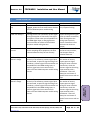
1
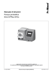
Revision: 2.0 FDPM-MKII Installation and User Manual FLOW DIFFERENTIAL PRESSURE MODULE® FDPM® MKII EU/IEC: Ex nA op is IIA T5 Gc ( II 3 G) Class 1, Zone 2, 3D (pending) For Automatic, Real Time Calculation of Corrected Differential Pressure during Refueling. INSTALLATION AND USER GUIDE Velcon Filters LLC, 1210 Garden of the Gods Road, Colorado Springs, Colorado, 80907, USA www.velcon.com Page 1 of 48 Revision: 2.0 FDPM-MKII Installation and User Manual 1 ‐ GENERAL 2 ‐ INSTALLATION 3 – SETUP / CONFIGURATION 3 – SETUP / CONFIGURATION 4 ‐ OPERATION 5 – TROUBLE‐ SHOOTING Phone (719) 531‐5855 Toll‐Free (800) 531‐0180 Fax (719) 531‐5690 [email protected] www.velcon.com Velcon Filters LLC, 1210 Garden of the Gods Road, Colorado Springs, Colorado, 80907, USA www.velcon.com Page 2 of 48 Revision: 2.0 FDPM-MKII Installation and User Manual TABLE OF CONTENTS 1 GENERAL DESCRIPTION ................................................................................. 5 1.1 Visual Outputs / Indicators .............................................................................................................. 5 1.2 Data Logging ..................................................................................................................................... 6 1.3 Data Outputs .................................................................................................................................... 6 1.4 Measurement Units .......................................................................................................................... 6 1.5 Alarm Triggers ................................................................................................................................... 6 1.5.1 Warning Alarms (FLASHING Yellow INDICATOR) ...................................................................... 6 1.5.2 Critical Alarms (FLASHING Red INDICATOR) ............................................................................. 6 1.6 Weight .............................................................................................................................................. 6 1.7 Safety / Compliance ......................................................................................................................... 6 1.8 Electrical Input Requirements .......................................................................................................... 6 1.9 Deadman Switch Relay ..................................................................................................................... 7 1.10 mechanical requirements ................................................................................................................ 7 1.11 Overall Dimensions .......................................................................................................................... 7 1.12 Safety Conventions ........................................................................................................................... 8 1.13 Operating Precautions ..................................................................................................................... 8 1.14 Package Contents ............................................................................................................................. 9 1.14.1 Inspect shipment ...................................................................................................................... 9 1.15 system requirements ..................................................................................................................... 10 2 INSTALLATION ............................................................................................. 13 2.1 3 SET UP / CONFIGURATION ........................................................................... 23 3.1 4 FDPM Module Mounting Instructions ........................................................................................... 13 2.1.2 Tools Needed ......................................................................................................................... 13 2.1.3 Determine Module Installation Location ............................................................................... 13 2.1.4 Drill / Tap Module Mounting Holes ........................................................................................ 15 2.1.5 Prepare and Install the FDPM Enclosure ................................................................................ 16 2.1.6 Route Cabling ......................................................................................................................... 17 2.1.7 Determine Proper Power and Sensor Polarity ....................................................................... 18 2.1.8 Make Final Wiring Connections ............................................................................................. 20 2.1.9 Test Functionality ................................................................................................................... 22 Quick Pressure Setup ..................................................................................................................... 23 3.1.1 Setting Number of Pressure Transducers Used and Scaling .................................................. 23 3.1.2 Setting Flow Scale Coefficient ................................................................................................ 25 3.1.3 System checkout and verification .......................................................................................... 26 3.1.4 System calibration .................................................................................................................. 27 OPERATION ................................................................................................. 28 4.1 4.2 Software Flow Chart ....................................................................................................................... 28 Software Navigation ....................................................................................................................... 29 4.2.1 Main Configuration Screen .................................................................................................... 30 4.2.2 Scaling / Filtering Menu ......................................................................................................... 31 Velcon Filters LLC, 1210 Garden of the Gods Road, Colorado Springs, Colorado, 80907, USA www.velcon.com Page 3 of 48 Revision: 2.0 FDPM-MKII Installation and User Manual 4.2.3 4.2.4 4.2.5 4.2.6 4.2.7 4.2.8 4.2.9 4.2.10 5 System Limits Submenu ......................................................................................................... 32 warning setup Submenu ........................................................................................................ 33 trending Submenu.................................................................................................................. 35 Misc (miscelaneous) Submenu............................................................................................... 36 SD Card Installation ................................................................................................................ 38 SD Card Setup ......................................................................................................................... 40 Data Logging and Retrieving Data .......................................................................................... 41 Warnings and Alerts ............................................................................................................... 41 TROUBLESHOOTING .................................................................................... 43 Velcon Filters LLC, 1210 Garden of the Gods Road, Colorado Springs, Colorado, 80907, USA www.velcon.com Page 4 of 48 Revision: 2.0 FDPM-MKII Installation and User Manual 1 GENERAL DESCRIPTION The FDPM‐MKII system consists of an embedded processing system coupled to an interactive touch screen which displays the Corrected Differential Pressure and the Flow Rate. The FDPM‐MKII can also display other relevant information regarding differential pressure calculations. FDPM‐MKII can display these in Imperial or Metric units, or a combination of both (USGPM, IGPM, PSI or LPM, bar). The FDPM‐ MKII automatically saves all CdP calculation readings to a Micro SD card (included with all FDPM‐MKII’s) In addition; this data can be easily downloaded to a USB Flash Drive through a built in USB port at the bottom of the FDPM‐MKII. Inputs to the FDPM are from 2 pressure transducers or a single differential pressure transducer capable of 4‐20 mA output, and a flow sensor/metering system such as a digital or mechanical fuel flow register or any other meter capable of a frequency output. Each input is scaled by a user set coefficient to ensure a wide range of compatibility with flow and pressure sensing equipment. The FDPM‐MKII operates on a 12‐ 24 VDC input power to ensure easy installation and safe operation in the intended operating environment. In the event that the filters exceed their pressure limit, the system will initiate an alarm sequence which will send a shutdown signal, tripping a relay, which can be tied to a refueling cart or truck deadman control circuit, thereby automatically disabling the fueling equipment and halting the flow of fuel. 1.1 VISUAL OUTPUTS / INDICATORS Interactive Color Touch Screen Daylight Readable Flashing Yellow Warning Indicator Flashing Red Critical Indicator Corrected Differential Pressure Actual Differential Pressure Flow Rate Peak Corrected and Actual Differential Pressure Real Time Corrected Differential Pressure Trending (Charting) Sudden DP Rise or Drop Alarm Velcon Filters LLC, 1210 Garden of the Gods Road, Colorado Springs, Colorado, 80907, USA www.velcon.com Page 5 of 48 1 ‐ GENERAL Velcon’s Flow Differential Pressure Module (FDPM) MK II is a computerized system designed to calculate, in real time, the Corrected Differential Pressure (CdP) of a filter vessel independent of flow rate, determining if the filters inside have reached the end of their useful life. This is done by considering current flow and differential pressure of the vessel against the rated flow and maximum differential pressure of the filters to find the corrected differential pressure. If the corrected differential pressure is higher than the set limit in mandated in the API/EI 1550 specification, the filters must be changed. The FDPM‐MKII is especially ideal in low flow applications. Revision: 2.0 FDPM-MKII Installation and User Manual 1.2 DATA LOGGING DATA OUTPUTS 1.4 1 ‐ GENERAL 1.3 Removable Micro SD Card (Included) >36 Months of Data (MS Excel Compatible) 60 Second Logging Interval (User Configurable) Stored Data is Easily Downloadable to a USB Flash Drive MEASUREMENT UNITS PSI, USGPM, IGPM, Bar, LPM 1.5 ALARM TRIGGERS 1.5.1 WARNING ALARMS (FLASHING YELLOW INDICATOR) 12 PSI or 0.8 Bar (User Configurable) Pressure Greater than System Rating Change in dP (User Configurable) 1.5.2 CRITICAL ALARMS (FLASHING RED INDICATOR) 1.6 WEIGHT 1.7 4 lbs (1.8 Kg) – FDPM‐MKII Module Only SAFETY / COMPLIANCE 1.8 External Switch Relay (Deadman) 15 PSI or 1.0 Bar (User Configurable) Change in dP (User Configurable) IP65 NEMA 4X ATEX Directive Class 1, Zone 2, Group 3D EU/IEC: Ex nA op is IIA T5 Gc ( II 3 G) ELECTRICAL INPUT REQUIREMENTS Power; 12‐24VDC only, 350mA minimum Flow; 0‐10V to 0‐30V alternating wave (square, sine, triangle) Pressure; 4‐20mA from either two single ended transducers or one differential transducer Velcon Filters LLC, 1210 Garden of the Gods Road, Colorado Springs, Colorado, 80907, USA www.velcon.com Page 6 of 48 Revision: 2.0 FDPM-MKII Installation and User Manual 1.9 DEADMAN SWITCH RELAY 3A @ 250VAC max. 1 ‐ GENERAL 1.10 MECHANICAL REQUIREMENTS Mounting plate, preferably out of direct sunlight and weather but not necessary Mounting hole pattern 4.33” (110 mm) X 5.51” (140 mm) 1.11 OVERALL DIMENSIONS Velcon Filters LLC, 1210 Garden of the Gods Road, Colorado Springs, Colorado, 80907, USA www.velcon.com Page 7 of 48 FDPM-MKII Revision: 2.0 Installation and User Manual 1.12 SAFETY CONVENTIONS Caution! In this document, this symbol expresses the need for extreme caution when performing the documented procedure. Failure to do so may cause harm to the user or the permanently damage the FDPM‐MKII. Important! This symbol expresses an important point or step in a procedure. Stop and read carefully before continuing. Note! This symbol expresses an important point to take note of for future reference. 1.13 OPERATING PRECAUTIONS The FDPM has been certified for Class 1, Zone 2, Group 3D operating environments. This implies that only under ABNORMAL circumstances will an explosive mixture of air and fuel vapors and an ignition source exist. If a situation arises that will result in an explosive mixture of air and fuel (vapors) in the FDPM‐MKII’s operating environment, during the installation, or maintenance of the FDPM‐MKII, or at any other time , power to the FDPM‐MKII must be de‐energized to avoid the risk of igniting the potentially explosive atmosphere. It is not the intention of Velcon Filters, LLC, to have the FDPM‐MKII system operate in conditions where there is a NORMALY occurring explosive mixture of gases, vapors, mists or air/dust mixtures. Fuel Compatibility The following table lists the compatibility of the FDMP MK II with common fuels. JET‐A1 Compatible JET‐A Compatible JET‐B NOT Compatible JP‐8 Compatible Aviation Gasoline (Avgas, Aviation Spirit) NOT Compatible Diesel (all grades) Compatible Motor Gasoline or Petrol NOT Compatible Velcon Filters LLC, 1210 Garden of the Gods Road, Colorado Springs, Colorado, 80907, USA www.velcon.com Page 8 of 48 1 ‐ GENERAL Revision: 2.0 FDPM-MKII Installation and User Manual 1.14 PACKAGE CONTENTS 1.14.1 INSPECT SHIPMENT The FDPM‐MKII system should consist of the following core components: 1 FDPM‐MKII Processing Unit 1 Installation and Operation Manual 1 Micro SD Card (May already be installed in the MK II processing unit) 1 4mm Allen Wrench/Key 2 Cable Gland Plugs Velcon Filters LLC, 1210 Garden of the Gods Road, Colorado Springs, Colorado, 80907, USA www.velcon.com Page 9 of 48 1 ‐ GENERAL Upon receipt of your FDPM system and before continuing, carefully remove and inspect the contents of the carton for damage or missing components. If any damage is visible, or components are missing from the carton, contact Velcon Filters immediately for disposition. Each FDPM‐MKII system carton should contain the following core components; Revision: 2.0 FDPM-MKII Installation and User Manual 1.15 SYSTEM REQUIREMENTS Because the FDPM‐MKII is a Corrected Differential Pressure calculation device, the system will need a minimum of three inputs to operate correctly; 1. Power ‐ Power will be in the form of 12‐24VDC with a minimum of 1A of current. 2. Pressure signal ‐ The pressure signal can be taken from a number of various pressure transducers on the market today which are capable of outputting a 4‐20mA signal. NOTE – Pressure “Transducers” must be used with the FDPM and not Pressure “Switches”. Velcon is available to assist in the selection of these types of instruments widely available on the market today. Velcon also offers both differential pressure transducers as well as single ended pressure transducers which are easily installed in standard 1/4” NPT fittings available on most fuel dispensing systems. Both of these sensors are available with Class 1, Div. 1, or Class 1, Zone 2, Group 3D (standard) ratings. When selecting pressure transducers, it is important to match them to the fueling systems maximum rated pressure and filter change out pressure. Example: If your refueling system is rated for 15 PSI change out, with a 150 PSI static pressure, you will likely choose a pressure transducer rated for 0‐25 PSI range, with a 150 PSI static pressure rating, which will yield the maximum accuracy for a standard off the shelf pressure transducer. If your system is rated for a change out pressure of 15 PSI but you use a transducer with 0‐150 PSI range, some accuracy will be lost with the larger range. Velcon Filters LLC, 1210 Garden of the Gods Road, Colorado Springs, Colorado, 80907, USA www.velcon.com Page 10 of 48 1 ‐ GENERAL Based on your purchase order, additional optional components may be included with the above core components. These may include: Description Quantity 1 Differential Pressure Transducer 2 Paired Pressure Transducers 1 Velcon Flow Sensor 1 Rotary Pulse encoder Revision: 2.0 FDPM-MKII Installation and User Manual Pressure Transducers Available from Velcon – Differential and Single Ended Transducers, shown here as Class 1, Zone 2, Group 3D Standard Classification. Class 1, Division 1 transducers are also available through Velcon. Liquip ERP200 Rotary Encoder ‐ May be Installed on Existing Liquip Mecahanical Registers. Velcon Filters LLC, 1210 Garden of the Gods Road, Colorado Springs, Colorado, 80907, USA www.velcon.com Page 11 of 48 1 ‐ GENERAL 3. Flow Signal – The flow signal must be in the form of an alternating wave (sine, square, triangle), with a 0‐10V minimum peak. The duty cycle does not have to be uniform as the FDPM onboard computer is very tolerant of misshapen wave forms. The pulse rate being output from a pulser is unimportant as this will be scaled in the FDPM software to match the exact flow rate of the system. In most cases, the flow signal will be taken directly from an existing Rotary Encoder or Pulser on the refueling vehicle such as in the case of the Veeder‐Root EMR3 system. If no such device is available, most register manufacturers have one available that is easily installed for use with the FDPM such as the Liquip ERP200 shown below. If no flow device is available as in cases of fuel farm and some older truck installations, Velcon offers a stand‐alone flow sensor which can be installed in an existing 1” NPT fitting. Contact Velcon Filters to discuss options in flow devices and flow signal outputs. Revision: 2.0 FDPM-MKII Installation and User Manual 1 ‐ GENERAL Stand‐Alone Flow Meter Available from Velcon – When no Pulse Output is Available. Velcon Filters LLC, 1210 Garden of the Gods Road, Colorado Springs, Colorado, 80907, USA www.velcon.com Page 12 of 48 Revision: 2.0 FDPM-MKII Installation and User Manual 2 INSTALLATION NOTE – To properly install and calibrate the FDPM‐MKII system, it is necessary to be able to operationally flow fuel through the refueling vehicle in a “closed loop” configuration at a known flow rate (USGPM, IGPM, or LPM). This allows the installation operator to check proper operation of the system and set the flow rate scaling. 2.1 FDPM MODULE MOUNTING INSTRUCTIONS The following is a list of tools that may be needed for a typical FDPM‐MKII refueling vehicle installation; Drill Drill bits as outlined in 2.1.4 below Taps as outlined in 2.1.4 below Wire strippers/cutters Digital multimeter with DC voltage, mA current, and frequency functions 2.1.3 DETERMINE MODULE INSTALLATION LOCATION Select an area which best suits the location of the FDPM Module, taking into consideration the following criteria; IMPORTANT ‐ Install strictly within regional and local fire codes for installation of equipment on aircraft fueling vehicles. This may require installing the FDPM Module within the cab when being installed on a refueling truck. Install preferably out of direct sunlight and weather. Although this is not necessary, following this guideline will help to increase the longevity of the unit. Install in an area which is easily viewed and accessible by operators during a refueling operation. Install in an area which will minimize cable runs, i.e., close to power, flow signal, and pressure sensors. Install in an area which will minimize exposure to fuel spillage. If installing Velcon provided Pressure Sensors, install as near as possible to the inlet and outlet of the filter vessel (see diagram below). If installing Velcon provided Pressure Sensors, install in areas which will minimize the vertical difference between the inlet and outlet of the sensors. The more vertical distance put between the inlet and outlet, the more error that will occur as a result of the additional weight of the column of fuel between the two sensors. Velcon Filters LLC, 1210 Garden of the Gods Road, Colorado Springs, Colorado, 80907, USA www.velcon.com Page 13 of 48 2 ‐ INSTALLATION 2.1.2 TOOLS NEEDED Revision: 2.0 FDPM-MKII Installation and User Manual 2 ‐ INSTALLATION Vessel Configuration with Corresponding Differential Pressure Transducer. Vessel Configuration with Corresponding Single Ended Pressure Transducers. Velcon Filters LLC, 1210 Garden of the Gods Road, Colorado Springs, Colorado, 80907, USA www.velcon.com Page 14 of 48 Revision: 2.0 FDPM-MKII Installation and User Manual 2.1.4 DRILL / TAP MODULE MOUNTING HOLES Once the installation location has been selected for the FDPM Module, mark the mounting hole locations using the 1:1 template on the back page (example template below). Drill/tap the holes as follows; If it is intended to tap the mounting holes, a typical tap size would be 1/4 ‐ 20 UNC or M6X1. If it is intended to drill through holes, a typical drill size would be 17/64” or 6.6 mm clearance holes. Velcon Filters LLC, 1210 Garden of the Gods Road, Colorado Springs, Colorado, 80907, USA www.velcon.com Page 15 of 48 2 ‐ INSTALLATION Vessel Configuration with Corresponding Rotary Pulse Encoder Input. Revision: 2.0 FDPM-MKII Installation and User Manual Velcon Filters LLC, 1210 Garden of the Gods Road, Colorado Springs, Colorado, 80907, USA www.velcon.com Page 16 of 48 2 ‐ INSTALLATION 2.1.5 PREPARE AND INSTALL THE FDPM ENCLOSURE The mounting holes for the FDPM are accessible only from the inside of the enclosure; therefore, the following steps will need to be taken to access them. Disengage the lid of the FDPM Module using the 4mm Allen key provided. Once opened, CAREFULLY disconnect the wiring harness from the CPU inside the enclosure as shown below by grasping each of the three terminal block connectors (J1, J2, and J3) and pulling straight out. It may also help to gently pry the connectors out using a flat tip screwdriver. Revision: 2.0 FDPM-MKII Installation and User Manual Once all three terminal block connectors are disengaged, disengage the USB cable from the CPU by grasping the USB plug and pulling straight out. Do not pull the USB plug out using the wires themselves. 2 ‐ INSTALLATION Once the wiring harness and USB Cable have been disconnected, the FDPM lid and CPU can be set aside. Be careful to protect the wiring harness and set the lid with the CPU touch screen face up. Using an appropriate socket head cap screw or equivalent, fasten the FDPM bottom enclosure to the designated location. A 1/4‐20 X 1.5” long socket head cap screw works well for fastening the enclosure to a 1/8” thick plate. 2.1.6 ROUTE CABLING Velcon Filters LLC, 1210 Garden of the Gods Road, Colorado Springs, Colorado, 80907, USA www.velcon.com Page 17 of 48 Revision: 2.0 FDPM-MKII Installation and User Manual Once the FDPM bottom enclosure has been securely mounted, route and secure cabling from the pressure sensor(s), flow signal, and power to the enclosure. It is best practice to leave a small service loop of cable for each of the three inputs at the bottom of the enclosure since there is very little room within the enclosure to store the service loops. 2 ‐ INSTALLATION 2.1.7 DETERMINE PROPER POWER AND SENSOR POLARITY It is extremely important to know the polarity of the input power to the FDPM Module, the pressure sensor(s), and the flow signal before attempting to make any wiring connections. Reversing polarity on any of these connections may result in unit damage or failure. Follow these guidelines to determine proper polarity for each; INPUT POWER – Red normally designates +V (+12 or +24 volts), while black or green normally designates ground. Determine the polarity of your power cable using a multimeter before attempting to make any connection and mark if needed. PRESSURE SENSOR – 4‐20mA output pressure sensors are normally used in a “Loop” configuration, meaning that they are connected between source power (+V) and signal as in the diagram below. Sensors provided by Velcon (Single Ended or Differential) will always come prewired with a black and red lead which will correspond directly to the wiring Velcon Filters LLC, 1210 Garden of the Gods Road, Colorado Springs, Colorado, 80907, USA www.velcon.com Page 18 of 48 Revision: 2.0 FDPM-MKII Installation and User Manual terminal colors on the wiring board terminal block. If using a pre‐existing pressure sensor, refer to the manufacturer’s pressure sensor manual for proper wiring configuration. 2 ‐ INSTALLATION Typical Wiring of a 4‐20mA Output Pressure Sensor FLOW SIGNAL – The flow signal will normally consist of a signal wire and a ground wire. Because each pulse transmitter manufacturer is different, it is imperative to consult the manufacturer’s user manual to determine which wires these may be. The flow signal wires will typically be taken from an interconnect box located within the cab of the refueling truck, although the signal may sometimes be taken directly from the pulse transmitter module. Velcon Filters LLC, 1210 Garden of the Gods Road, Colorado Springs, Colorado, 80907, USA www.velcon.com Page 19 of 48 Revision: 2.0 FDPM-MKII Installation and User Manual 2.1.8 MAKE FINAL WIRING CONNECTIONS Once all wiring and polarity has been positively determined, complete the following wiring steps; connections. Failure to do this may result in unit damage or failure. Route each cable through an appropriate cable gland close to its respective wiring terminal and tighten the cable gland enough to create a seal, but being careful not to crush the cable. Once all cables are routed through the cable glands, loop the excess cables as shown below and make the appropriate connections. When connecting wires to the terminal block, ensure that the wire ends are properly twisted so that stray wire strands do not bridge to neighboring terminals. Also, ensure that each wire is properly and fully seated within its respective terminal and tightened securely. For standard installations, VOLTAGE INPUT, DIFF. PRESS., LOW PRESS., HGH PRESS., and PULSE INPUT will be used. The RELAY OUTPUT for using a Deadman switch will be described below. Insert cable gland plugs (provided) in any unused cable glands. Wire Connection Board – The Inputs Circled in Red are Used for Standard Installations. Velcon Filters LLC, 1210 Garden of the Gods Road, Colorado Springs, Colorado, 80907, USA www.velcon.com Page 20 of 48 2 ‐ INSTALLATION IMPORTANT – Disengage main power to truck BEFORE attempting to make any wiring Revision: 2.0 FDPM-MKII Installation and User Manual NOTE – If one Differential pressure sensor is being used, connect its wiring terminations to the “DIFF PRESS” terminal block location. If two Single Ended pressure sensors are being used, connect the High Pressure sensor wiring terminations to the “HIGH PRESS” terminal block location, and the Low Pressure sensor wiring terminations to the “LOW PRESS” terminal block location. Deadman – If using the Deadman switch capabilities of the FDPM system, wire to the RELAY OUTPUT on the FDPM Wire Connection Board. The Relay Output can be set up in a Normally Open (N/O) or Normally Closed (N/C) configuration, with the Common wire being connected to the COMM terminal. See Section 1.9 for relay voltage and current handling specifications. 2 ‐ INSTALLATION Once all wires are securely fastened to the terminal block, carefully reinstall the enclosure lid. First reattach the wiring harness by plugging the connector back into the receptacle. NOTE – This connector is polarized and must be plugged in with the proper orientation. Note the keying notch when reseating the connector. Plug the Serial Cable back into the RJ‐ 45 Jack, and carefully reinstall the lid and Touch Screen, ensuring that all wires and cables are out of the way of the lids seating channel. Velcon Filters LLC, 1210 Garden of the Gods Road, Colorado Springs, Colorado, 80907, USA www.velcon.com Page 21 of 48 Revision: 2.0 FDPM-MKII Installation and User Manual 2.1.9 TEST FUNCTIONALITY Once the FDPM has been reassembled, it can be tested for functionality using the following steps; Velcon Filters LLC, 1210 Garden of the Gods Road, Colorado Springs, Colorado, 80907, USA www.velcon.com Page 22 of 48 2 ‐ INSTALLATION Engage power to the refueling vehicle and watch the FDPM LCD screen to ensure it boots up properly. Note that unless fuel is running through the system, the differential pressure and flow rate readings should read all zeros at this point. If the LCD screen boots up properly and displays zeros you are ready to test the sensor inputs. Set the refueling vehicle up to flow fuel in a closed loop configuration. This will allow a functional test of both the flow signal and pressure signal(s) coming in to the FDPM Module. Flow the fuel system and observe the differential pressure reading and flow reading immediately upon fuel circulation. Although the numbers may be off from actual pressure and flow rates, the zero readings should begin to change. If a change in these readings is observed, then the system is ready to be configured. If no change is observed, refer to the Troubleshooting Guide in Section 6. Revision: 2.0 FDPM-MKII Installation and User Manual 3 3.1 QUICK PRESSURE SETUP Velcon ships the FDPM‐MKII with standard coefficients which are based on pressure sensors provided. Because the flow scaling will vary depending on the wide variety of available pulse encoders or flow sensors used, this scaling coefficient will usually need to be set by the user after installation. Contact Velcon to help you determine what your scaling coefficients should be based on the existing equipment you have. 3.1.1 SETTING NUMBER OF PRESSURE TRANSDUCERS USED AND SCALING Follow the steps below to set the number of pressure sensors used; Press below the LCD screen. Velcon Filters LLC, 1210 Garden of the Gods Road, Colorado Springs, Colorado, 80907, USA www.velcon.com Page 23 of 48 3 – SETUP / CONFIGURATION SET UP / CONFIGURATION Once functionality has been verified, there are a few initial setup procedures that are required. These setup procedures will be accessible through the FDPM‐MKII user interface. The following procedure can only be carried out by an operator who has been assigned a “Passcode”. A Passcode is required to access certain configuration screens. The factory default Passcode is “123” and may be changed to any three to five digit number through the Misc menu. For security purposes, this number must be used to access the configuration menu. If the Passcode is changed and the number forgotten, you will be locked out of the system. If this happens, you must contact Velcon to for a resetting sequence. At minimum, the following parameters must be configured for the FDPM‐MKII to function properly: Setting the Date and Time. Setting the maximum filter/monitor replacement or “Changeout” differential pressure value. Setting the maximum rated flow of the overall system. Setting the number of pressure transducers used with the FDPM‐MKII. Setting the scale and offset for the flow sensor or pulser being used. Setting the scale and offset for the pressure sensors being used. Refer to the following sections to set scaling and offsets for pressure and flow sensors. Revision: 2.0 FDPM-MKII Installation and User Manual Password Screen. Configuration Screen. Misc. Menu. Scaling/Filtering Menu. Miscellaneous Menu Scroll down to the “Num Pr. Sensors” line and press enter. Use the Up and Down arrows to select “1 dPr” or “2 Pr” depending on whether one Differential Pressure sensor or two Single Ended sensors are being used, then press Enter. Press “Esc” to exit the Misc menu. Velcon Filters LLC, 1210 Garden of the Gods Road, Colorado Springs, Colorado, 80907, USA www.velcon.com Page 24 of 48 4 ‐ COFIGURATION 3 – SETUP / CONFIGURATION Password Screen Enter the password “1 2 3” at the prompt (This may be changed to any user passcode. See details in the OPERATION section of the manual). Once the password has been entered, the Configuration Screen is displayed. Pressing “Misc.” displays the following screen: Revision: 2.0 FDPM-MKII Installation and User Manual Scaling/Filtering Menu Press the Scaling/Filtering menu, then enter the correct scale and offset for the pressure sensor configuration of your system. EXAMPLE: If using Velcon supplied differential pressure transducer, 0‐25 PSID, at 4‐20mA output, the Press. Scale will be 1.25, and Press. Offset will be 0. If using Velcon supplied single ended pressure transducers, 0‐150 PSID, at 4‐20mA output, the Press. Scale will be 7.5, and Press. Offset will be 0. Contact Velcon if using sensors that do not fit these criteria. 3.1.2 SETTING FLOW SCALE COEFFICIENT Flow Scale Computation Screen. Enter the Actual Flow Rate as read from another available flow meter during closed loop fuel circulation, and press Compute Scaling. The new flow scale coefficient will automatically be calculated and entered in the flow scale. NOTE – For automatic flow scale computation to be accurate, the vehicles system MUST be kept at a known and steady flow rate for the duration of the operation. Velcon Filters LLC, 1210 Garden of the Gods Road, Colorado Springs, Colorado, 80907, USA www.velcon.com Page 25 of 48 3 – SETUP / CONFIGURATION Follow the steps below to set the flow scale coefficient; Once at the Scaling screen, there are two ways to set the flow scale coefficient. If you know the flow scale coefficient, simply enter it in for Flow Scale. If you do not know the coefficient, the FDPM will calculate it for you based on a known flow rate taken from another flow meter within the system. To do this, enter Compute Flow which will open the following screen; Revision: 2.0 FDPM-MKII Installation and User Manual 3.1.3 SYSTEM CHECKOUT AND VERIFICATION Once the FDPM‐MKII has been properly installed, wired, and configured, the following steps may be used to verify that it is functioning properly; One Differential Pressure Sensor Used. Two Single Ended Pressure Sensors Used. Velcon Filters LLC, 1210 Garden of the Gods Road, Colorado Springs, Colorado, 80907, USA www.velcon.com Page 26 of 48 3 – SETUP / CONFIGURATION Set the fueling vehicle up and flow fuel in a continuous closed loop configuration. In the Miscellaneous menu, scroll down to “Show Raw Data”. Observe the “Flow Input (Hz)” (which corresponds to flow rate), and “Press. Sensor In X (mA)” (which corresponds to pressure) boxes. Depending on whether one differential or two single ended sensors are being used, the screen will look like one of the pictures below. NOTE – The values shown in these boxes represent “raw” signals coming in to the FDPM module BEFORE scaling and offsets are applied. They will likely not match Actual DP or Flow values being displayed. Verify that the “Flow Input (Hz)” number displayed contains something other than 0 if there is flow present. Verify that the “Press. Sensor In 1 (mA)” and “Press. Sensor In 2 (mA)” numbers each display something greater than 0 if two single ended pressure sensors are being used. If a number significantly less than this is displayed for either of the sensors, that pressure sensor is likely not making a connection or is connected backwards. If a differential pressure sensor is being used, the “Press. Sensor In Diff(mA)” number should be something greater than zero. If this procedure checks okay, the system is working and ready for use. Go back to the main screen and verify Actual DP, Corrected DP, and Flow Rate are correct. If they are not, the system has not been properly scaled. Go back through Sections 3.1.1 and 3.1.2 to scale the system. If one or more of these parameters is not working properly, refer to the Troubleshooting Guide in Section 5. Revision: 2.0 FDPM-MKII Installation and User Manual 3.1.4 SYSTEM CALIBRATION The calibration of system components is as follow; FDPM‐MKII computer module – Unless certifications are required, the computer module typically only needs verification on an annual basis. This can be completed by a technician knowledgeable of general electronics, using calibrated frequency and current generators. NOTE – The computer module has an onboard clock accuracy of +/‐ 7 minutes per month. It may be necessary to adjust the time in the Date/Time screen on regular intervals to keep an accurate record of critical events. Differential and Single Ended pressure transducers – One year intervals per manufacturers suggested guidelines. Flow Meter – One year intervals per manufacturers suggested guidelines. It is the responsibility of the equipment installation, operation, and user personnel to arrange for calibration of this equipment at manufacturer suggested intervals. Velcon assumes no responsibility for equipment calibration. 3 – SETUP / CONFIGURATION Velcon Filters LLC, 1210 Garden of the Gods Road, Colorado Springs, Colorado, 80907, USA www.velcon.com Page 27 of 48 Revision: 2.0 FDPM-MKII Installation and User Manual 4 OPERATION 4.1 SOFTWARE FLOW CHART The flow chart below is a quick reference to any user function throughout the FDPM software. 4 ‐ OPERATION Velcon Filters LLC, 1210 Garden of the Gods Road, Colorado Springs, Colorado, 80907, USA www.velcon.com Page 28 of 48 Revision: 2.0 FDPM-MKII Installation and User Manual 4.2 SOFTWARE NAVIGATION The user interface of the FDPM‐MKII consists of 5 buttons and an interactive touch screen display. The initial configuration of the unit is performed using primarily the touch screen display. Once the initial configuration is complete, the 4 Function buttons (F1, F2, F3, and F4) will be primarily needed for normal operations. The button allows access to certain system configuration settings. This button is never used during normal operation and is disabled by default. The button shows the main screen of the FDPM‐MKII (Current Corrected Differential Pressure and Current Flow Rate). The FDPM‐MKII will always return to this default screen. The button shows the current and maximum values for the current refueling session. The button shows a trending chart of the corrected differential pressure for the current refueling session. The button allows access to the FDPM‐MKII configuration settings. Pressing the button and entering the correct passcode (1 2 3 initially) on the touch screen opens the main Configuration Menu. Using the interactive touch screen, press the desired submenu to continue. Velcon Filters LLC, 1210 Garden of the Gods Road, Colorado Springs, Colorado, 80907, USA www.velcon.com Page 29 of 48 4 ‐ OPERATION Revision: 2.0 FDPM-MKII Installation and User Manual 4.2.1 MAIN CONFIGURATION SCREEN Bootup Screen. Main Configuration Menu. The Main Configuration Screen is used to access all other parameters used within the FDPM‐ MKII system software tree. In addition to this, the SD Card Setup and USB Copy parameters are accessed from this menu. Velcon Filters LLC, 1210 Garden of the Gods Road, Colorado Springs, Colorado, 80907, USA www.velcon.com Page 30 of 48 4 ‐ OPERATION Revision: 2.0 FDPM-MKII Installation and User Manual 4.2.2 SCALING / FILTERING MENU Scaling/Filtering submenu. The Scaling/Filtering menu is primarily used when first configuring the FDPM‐MKII system. It provides scaling for the flow input and CdP calibration, and filtering when “noise” is encountered with a flow signal input or CdP device. 4 ‐ OPERATION Velcon Filters LLC, 1210 Garden of the Gods Road, Colorado Springs, Colorado, 80907, USA www.velcon.com Page 31 of 48 Revision: 2.0 FDPM-MKII Installation and User Manual 4.2.3 SYSTEM LIMITS SUBMENU System Limits submenu The Scaling/Filtering menu is primarily used when first configuring the FDPM‐MKII system. It is used to enter and store the fueling systems rated changeout dP and flow. Velcon Filters LLC, 1210 Garden of the Gods Road, Colorado Springs, Colorado, 80907, USA www.velcon.com Page 32 of 48 4 ‐ OPERATION Revision: 2.0 FDPM-MKII Installation and User Manual 4.2.4 WARNING SETUP SUBMENU Warning Setup submenu The Warning/Shutdown menu is used to configure trigger points for Warnings, Critical Warnings, and Shutdown of the fuel system using the deadman control. Note – The deadman control follows the Critical/Shutdown Warnings, so whenever a Critical/Shutdown Warning is triggered, the deadman control is also activated. Example Flashing Critical Indicator Velcon Filters LLC, 1210 Garden of the Gods Road, Colorado Springs, Colorado, 80907, USA www.velcon.com Page 33 of 48 4 ‐ OPERATION Example Flashing Warning Indicator Revision: 2.0 FDPM-MKII Installation and User Manual Velcon Filters LLC, 1210 Garden of the Gods Road, Colorado Springs, Colorado, 80907, USA www.velcon.com Page 34 of 48 4 ‐ OPERATION Revision: 2.0 FDPM-MKII Installation and User Manual 4.2.5 TRENDING SUBMENU Trending submenu The Warning/Shutdown menu is used to configure trigger points for Warnings, Critical Warnings, and Shutdown of the fuel system using the deadman control. Note – The deadman control activates with Critical/Shutdown Warnings, so whenever a Critical/Shutdown Warning is triggered, the deadman control is also activated. 4 ‐ OPERATION Velcon Filters LLC, 1210 Garden of the Gods Road, Colorado Springs, Colorado, 80907, USA www.velcon.com Page 35 of 48 Revision: 2.0 FDPM-MKII Installation and User Manual 4.2.6 MISC (MISCELANEOUS) SUBMENU 4 ‐ OPERATION Misc. submenu 1. Misc. submenu 2. Velcon Filters LLC, 1210 Garden of the Gods Road, Colorado Springs, Colorado, 80907, USA www.velcon.com Page 36 of 48 Revision: 2.0 FDPM-MKII Installation and User Manual The Misc. menu is used to configure a variety of parameters, some of which will be used in the initial setup and configuration of the FDPM‐MKII system, whereas others are used for security purposes. Velcon Filters LLC, 1210 Garden of the Gods Road, Colorado Springs, Colorado, 80907, USA www.velcon.com Page 37 of 48 4 ‐ OPERATION Revision: 2.0 FDPM-MKII Installation and User Manual 4.2.7 SD CARD INSTALLATION After removing the cover of the FDPM, look for a stamped symbol of a Micro SD card on the rear of the processing unit for the correct orientation. On the Top face of the processing unit, the text “MEMORY” is written in white lettering, and in the back of the “MEMORY” stamp is the slot to insert the Micro SD Card. 4 ‐ OPERATION Velcon Filters LLC, 1210 Garden of the Gods Road, Colorado Springs, Colorado, 80907, USA www.velcon.com Page 38 of 48 Revision: 2.0 FDPM-MKII Installation and User Manual Insert a Micro SD Card in the slot behind the white “MEMORY” text. Press the Micro SD Card into position until it engages and locks into place. DO NOT FORCE THE CARD. Removal of the Micro SD Card is the opposite of its installation. Gently press the top of Micro SD Card until it disengages from its locked position and partially ejects. 4 ‐ OPERATION Velcon Filters LLC, 1210 Garden of the Gods Road, Colorado Springs, Colorado, 80907, USA www.velcon.com Page 39 of 48 Revision: 2.0 FDPM-MKII Installation and User Manual 4.2.8 SD CARD SETUP SD Card Setup submenu. Velcon Filters LLC, 1210 Garden of the Gods Road, Colorado Springs, Colorado, 80907, USA www.velcon.com Page 40 of 48 4 ‐ OPERATION Revision: 2.0 FDPM-MKII Installation and User Manual 4.2.9 DATA LOGGING AND RETRIEVING DATA The FDPM‐MKII has the capability of logging data to the Micro SD Card which can be retrieved at any time by simply plugging a USB flash drive into the USB port located at the bottom of the FDPM‐MKII. Once the USB drive is in place, press the key, then the key. Allow adequate time for the entire contents of the Micro SD Card to be copied to the USB flash Drive. If the flash drive is remove to soon, the copy process will not be complete. 4.2.10 WARNINGS AND ALERTS Alerts The FDPM‐MKII has the capability of alerting an operator or supervisor of abnormal operating conditions when refueling. The FDPM‐MKII has both yellow and red flashing warning indicators on the color touch screen. In the event of the FDPM‐MKII detecting a user set abnormal or dangerous condition during fueling operations, and depending on the severity of the condition, the yellow, the red, or both warning indicators will begin flashing. Warning Alerts (yellow) inform the user of conditions that are outside of normal operating guidelines, but are not threatening. Critical Alerts (red) indicate dangerous or unsafe conditions in which the refueling session must be halted immediately. All Warning Alerts and Critical Alerts are user programmable. Warning Alert (Yellow flashing indicator) 4 ‐ OPERATION Warning Alert overrides When a Warning Alert has been activated, the alert status will remain activated until the out of spec parameter returns to normal. This is the only way to deactivate a Warning Alert. Velcon Filters LLC, 1210 Garden of the Gods Road, Colorado Springs, Colorado, 80907, USA www.velcon.com Page 41 of 48 Revision: 2.0 FDPM-MKII Installation and User Manual Critical Alert (Red flashing Indicator) Critical Alert overrides When a Critical Alert has been activated, the alert status will remain activated until a Change Code has been entered. This is normally set up to be performed ONLY by a supervisor. Unless the out of spec condition has been attended to, the Critical Alert will re‐activate when fueling is resumed. Under normal operating conditions, the deadman control is tied to the FDPM‐MKII so that when a Critical condition is encountered, the fueling operation is immediately ceased and a supervisor must be alerted before the fueling operation can be resumed. 4 ‐ OPERATION Velcon Filters LLC, 1210 Garden of the Gods Road, Colorado Springs, Colorado, 80907, USA www.velcon.com Page 42 of 48 Revision: 2.0 FDPM-MKII Installation and User Manual 5 TROUBLESHOOTING Problem Possible Cause Unit does not power Power not connected, Vehicle power not up engaged, power wire has come loose or broken off from FDPM computer module wiring harness. Flow rate always 0. Flow signal wires not connected, no flow signal coming from pulser or flow meter, flow signal from pulser or flow meter not compatible with the FDPM digital input, or flow signal wires have come loose or broken off from FDPM computer module wiring harness. Flow rate is not correct. If the flow rate changes with flow but is not correct according other equipment, the flow scale and offset are likely not set correctly. Recommended Fix Check power to the FDPM unit, inspect all wiring. Inspect flow signal wiring for loose or broken connections, check flow signal at the wiring input terminals, ensure a waveform exists with a 0‐10V minimum output. Check flow scale and offset and set to correct values, use Compute Flow to calculate flow rate. Refer to Section 3.1.1 to set the number of sensors, inspect pressure signal wiring for loose or broken connections, check the pressure signal at the wiring input terminals with a multimeter. There will always be a minimum of 4mA of current even with no flow. Refer to Section 3.1.1 to set Number of pressure sensors has not been set correctly in the software, pressure signal wires the number of sensors, not connected, no pressure signal coming from inspect pressure signal transducer, pressure signal from transducer not wiring for loose or broken connections, check the compatible with the FDPM analog input, or pressure signal at the wiring pressure signal wires have come loose or broken off from FDPM computer module wiring input terminals with a multimeter. There will harness. always be a minimum of 4mA of current even with no flow. Differential pressure Number of pressure sensors has not been set doesn't change. correctly in the software, pressure signal wires not connected, no pressure signal coming from transducer, pressure signal from transducer not compatible with the FDPM analog input, or pressure signal wires have come loose or broken off from FDPM computer module wiring harness. Absolute pressure doesn't change. www.velcon.com Page 43 of 48 5 – TROUBLE‐ SHOOTING Velcon Filters LLC, 1210 Garden of the Gods Road, Colorado Springs, Colorado, 80907, USA Revision: 2.0 FDPM-MKII Installation and User Manual Diff. pressure not correct. Abs. pressure not correct. Abs. pressure does not correspond with Gammon gage. If the diff. pressure changes but is not correct according other equipment, the number of pressure sensors or the pressure scale and offset are likely not set correctly. If the diff. pressure changes but is not correct according other equipment, the number of pressure sensors or the pressure scale and offset are likely not set correctly. Pressure scale and offset not set correctly. Refer to Section 3.1.1 to set the number of sensors, check and adjust pressure scale and offset. Refer to Section 3.1.1 to set the number of sensors, check and adjust pressure scale and offset. Adjustments can be made to pressure OFFSET to "shift" scale to match Gammon gage. Contact Velcon for instruction on how to reset passcode. Check Changecode in the Misc. Menu Check and remedy the condition that is causing the Warning condition. Passcode being entered is different from the passcode set in the system. Changecode does not work Warning indicator (Yellow) will not turn off. Passcode being entered is different from the passcode set in the system. The parameter causing the warning has not returned to an acceptable limit. Critical indicator (Red) will not turn off. The Critical Indicator will NOT turn off when then the parameter causing the critical state has returned to normal. When the system has entered this state, the Change Code must be entered by authorized personnel. Wiring for deadman not connected to Relay Ouput on the Wire Connection Board. Wiring on N/O and N/C switch terminals reversed, Critical warnings set with too wide of parameters to energize relay. Check and remedy the condition that is causing the Critical condition. Alert the appropriate supervisor to enter the Change Code. Inspect deadman wiring for loose or broken connections, ensure N/O and N/C terminals are not reversed, check for Critical warnings. There is no Micro SD card present, the card has been physically damaged or corrupted. Check for SD card presence, replace SD card. There is no Micro SD card present, the card has been physically damaged or corrupted. Contact Velcon Filters, LLC Check for SD card presence, replace SD card. Deadman does not shut down flow. The letters "SD" blink at the top of screen. SD card setup sub menu flashing. All other problems Velcon Filters LLC, 1210 Garden of the Gods Road, Colorado Springs, Colorado, 80907, USA www.velcon.com Page 44 of 48 5 – TROUBLE‐ SHOOTING Passcode does not work Revision: 2.0 FDPM-MKII Installation and User Manual Terms and Conditions On Manufactured Products EXCLUSIVE LIMITED WARRANTY THE PRODUCTS SOLD HEREUNDER SHALL BE OF A MERCHANTABLE QUALITY AND SHALL CONFORM TO SELLER’S CURRENT STANDARD SPECIFICATIONS OR SUCH OTHER SPECIFICATIONS AS SHALL HAVE BEEN MADE EXPRESSLY A PART OF THIS CONTRACT. SELLER MAKES NO OTHER WARRANTY, EXPRESS OR IMPLIED, OF FITNESS FOR A PARTICULAR USE, PURPOSE OR OTHERWISE, WHETHER USED SINGLY OR IN COMBINATION WITH OTHER PRODUCTS OR IN ANY PROCESS. LIMITATION OF LIABLITIY Defective or nonconforming products shall be repaired or replaced by Seller without additional charge, or in lieu thereof, at Seller’s option, Seller may refund the purchase price upon return of the products at Seller’s expense. NOTWITHSTANDING THE ABOVE AND REGARDLESS OF THE CIRCUMSTANCES, SELLER’S TOTAL LIABILITY TO BUYER FOR ANY AND ALL CLAIMS, LOSSES OR DAMAGES ARISING OUT OF ANY CAUSE WHATSOEVER, WHETHER BASED IN CONTRACT, NEGLIGENCE OR OTHER TORT, STRICT LIABILITY, BREACH OF WARRANTY OR OTHERWISE, SHALL IN NO EVENT EXCEED THE PURCHASE PRICE OF THE PRODUCTS IN RESPECT TO WHICH SUCH CAUSE AROSE. IN NO EVENT SHALL SELLER BE LIABLE FOR SPECIAL, INCIDENTAL, CONSEQUENTIAL OR EXEMPLARY DAMAGES. Any cause of action that Buyer may have against Seller and which may arise under this contract must be commenced within one year after the cause of action has accrued. PRICE Unless otherwise specified, price includes domestic packaging and transportation to the specified FOB point. Buyer will pay any additional transportation charges. Prices do not include any federal, state or local taxes, assessments, or import duties applicable to the sale, ownership, production, transportation or use of goods sold. Any such tax or duties shall be separately itemized on Seller’s invoice and paid by Buyer or, in lieu thereof, Buyer shall furnish Seller with a valid tax exemption certificate. In the event Seller is required to pay any such tax or assessments, Buyer shall reimburse Seller upon demand, plus interest on such amount at the rate of ten percent (10%) per annum from the date paid by Seller. Seller shall be under no obligation to contest the validity of any such tax or assessments or to prosecute any claims or refunds or returns. Any personal property taxes or similar taxes or assessments against the goods or on account of materials segregated for the Buyer and being held by the Seller at Buyer’s request shall be paid by Buyer. SHIPMENTS AND PACKAGING Unless otherwise agreed in writing, all shipments shall be FOB Seller’s plant or plants, and title passed to Buyer upon delivery to carrier at such point, and packaging will be accomplished in accordance with Seller’s standard commercial practice for domestic shipments. Seller may ship goods to the Buyer’s place of business by such means as Seller shall select if adequate shipping instructions are not received from Buyer within sixty (60) days before the shipment date. Buyer accepts all risk of loss or damage thereto, upon delivery of goods by Seller to a carrier, shipper, forwarding agent, transporter, or Government mail box or post office, whether selected by Buyer or Seller. In no event shall Seller be responsible for any goods after delivery to such shipping means. PAYMENTS On open accounts, terms of payment are net thirty (30) days from date of invoice, unless otherwise agreed to in writing. Buyer agrees to pay Seller’s finance charges (10% per annum) for late payments, and any expenses in collecting such unpaid balance and finance charges, or in recovering possession of the goods. On all other accounts, payments are FOB factory. ACCEPTANCE Buyer shall inspect all goods immediately upon their delivery to the destination stated in the Agreement and shall within ten (10) days provide written notice to Seller at its principal place of business of any claim that the goods do not conform to the terms of the Agreement. Any such notice shall specify with particularity each alleged defect or nonconformity. If Buyer shall fail to give such timely notice, the goods shall be conclusively deemed to conform to the terms and specifications of this Agreement and shall constitute an irrevocable acceptance of the goods. Any use by Buyer of the goods other than solely for test purposes, or any alteration of the goods by Buyer without Seller’s prior written consent, shall be conclusive and binding evidence that the goods conform to the terms and specifications of this Agreement. If Buyer accepts or is deemed to have accepted the goods as herein above provided, Buyer shall not be entitled to revoke acceptance thereof at a subsequent time. In the event Buyer timely rejects the goods in accordance with the terms of this Agreement, Buyer shall hold the goods without charge to Seller for a reasonable time until Seller gives instructions to Buyer with respect to the goods. Should Buyer sell or dispose of the goods without Seller’s written approval, such sale or disposition shall constitute an unequivocal acceptance of the goods, notwithstanding any prior rejections of the goods. CANCELLATIONS Once an order has entered the Velcon manufacturing process, or for stock items if already picked and packed, it cannot be cancelled without receiving written authorization by Velcon Management. Cancelled orders will be subject to a cancellation fee; the amount will be based on the value of the work completed but will not be less than 20% of the original order value. Please also note that some manufactured products will have a cancellation fee of up to 80% of the value of the original order. Velcon Filters LLC, 1210 Garden of the Gods Road, Colorado Springs, Colorado, 80907, USA www.velcon.com Page 45 of 48 Revision: 2.0 FDPM-MKII Installation and User Manual EXCUSABLE DELAYS Seller shall not be liable for damages for delays in performance due to circumstances beyond its reasonable control, including with limiting the generality of the foregoing, any priority system established by any agency of the United States Government, fires, floods, storms, and other Acts of God, accidents, strikes, insurrections, war, acts of terrorism, shortage of materials, lack of transportation and failure of performance of subcontractors and/or suppliers for similar reasons. Failure of Seller to perform for these reasons aforesaid shall not be grounds for Buyer’s cancellation of its order but the delivery date shall be extended accordingly. Buyer’s acceptance of late delivery goods shall constitute complete and satisfactory performance by Seller. PATENT INDEMNITY If the goods furnished hereunder are specified in this Agreement as being standard commercial supplies of Seller, Seller agrees to indemnify Buyer, its successors, assigns, agents and use of its products against loss, damage, or liability, including cost and expenses, which may be incurred on account of any suit, claim, judgment or demand involving infringement or alleged infringement of any patent rights in the manufacture, use or disposition of any goods supplied hereunder, provided Buyer shall promptly notify Seller of any suit instituted against it and, to the full extent of its ability to do so, shall permit Seller to defend the same or make settlement in respect thereto. In the event the goods furnished hereunder are produced under special specifications of Buyer, no liability under this paragraph shall arise against Seller. In like manner, Buyer agrees to save Seller harmless from patent infringements resulting from Seller’s compliance with designs and/or specifications not originating with Seller now or hereafter forming a part of this Agreement or with specific written instructions given by Buyer for the purpose of directing the manner in which Seller shall perform this Agreement. USE OF PRODUCTS Seller grants no license or right, expressly or by implication, estoppel, or otherwise, beyond the right of the Buyer to use the specified goods in the form delivered by Seller. Further, Seller’s products are offered for sale and are sold subject in every case to the condition that such sale does not convey any license, expressly or by implication, estoppel, or otherwise under any patent claim with respect to which Seller could grant licenses covering any other product, or any completed equipment, or any assembly, piping spool, circuit, combination, method or process in which, or in the manufacturing or testing of which, any such Seller products are used (notwithstanding that such Seller products may have been designed only for use in, or may only be useful in, such other patented products or such patented equipment, assembly, piping spool, circuit, combinations, method or process, or in the manufacturing or testing thereof, and that Seller products may have been purchased and sold for such use). Seller expressly reserves all its rights under such patent claims. PROPRIETARY RIGHTS The prints, drawings or specifications of Seller attached hereto or hereafter furnished by Seller to Buyer in connection with the obtaining or the performance of this Agreement are the property of the Seller and represent a proprietary article with respect to which Seller retains all United States or foreign letters patent, trademarks or copyrights, including exclusive rights of use, manufacture and sale. Possession by Buyer of such prints, drawings or specifications does not convey any permission to manufacture, use or sell any goods shown thereon and such information is disclosed to Buyer on a confidential basis. COMPLIANCE WITH LAWS AND REGULATIONS Buyer agrees to indemnify and hold Seller harmless against all losses, claims, causes of action, penalties and liabilities arising out of Buyer’s failure to comply with all applicable federal, state and local laws, ordinances, regulations, rules and orders. TERMINATION If Buyer fails to comply with any of the provisions hereto, or becomes the subject of a proceeding under state or federal law for relief of debtors, or makes an assignment for the benefit of creditors, Seller shall have the right to hold Buyer in default and, in addition to any other rights it may have, may cancel this Agreement in whole or in part. EFFECT OF INVALIDITY The invalidity in whole or in part of any provision hereto shall not affect the validity of any other provisions. CREDIT Seller reserves the right at any time to alter or suspend credit, or to change credit terms provided herein, when in its sole opinion the financial condition of the Buyer so warrants. In such case, in addition to any other remedies herein or by law provided, cash payment or satisfactory security from Buyer may be required by Seller before shipment, or Seller may, at its option, defer further shipments to Buyer until Buyer reestablishes satisfactory credit, cancels the unshipped portion, with a twenty‐five percent (25%) cancellation fee, of the order without any liability for failure to ship, or makes shipments to Buyer on a prepayment basis. Payments made by trade acceptances, notes, securities, postdated checks, etc. are unacceptable unless first approved in writing by Seller. REMEDIES The rights and remedies provided Seller herein shall be cumulative, and in addition to any other rights and remedies provided by law or equity. Seller’s failure to insist upon strict performance of any provision of the Agreement shall not be deemed to be a waiver of Seller’s right or remedies, nor a waiver by Seller of any subsequent default by the Buyer in performance of or a waiver by Seller of any subsequent default by the Buyer in performance of or compliance with any of the terms of this Agreement. Velcon Filters LLC, 1210 Garden of the Gods Road, Colorado Springs, Colorado, 80907, USA www.velcon.com Page 46 of 48 Revision: 2.0 FDPM-MKII Installation and User Manual ASSIGNMENT Buyer may not assign this Agreement, or any portion thereof without the express prior written consent of Seller. Subject always to the foregoing, this Agreement insures to the benefit of, and is binding upon, the heirs, legatees, personal representatives, successors and assigns of the parties hereto, in no event shall assignment relieve Buyer of liability for performance of the obligations imposed by this Agreement. ENTIRE AGREEMENT This Agreement shall constitute the entire understanding of the parties with reference to the subject matter hereof, and it is agreed that there are no understandings, promises, representations or agreements, whether oral or written, heretofore entered into between Seller and Buyer which have any force or effect. This Agreement may be amended only by a writing signed by the parties. No agent, employee, or representative of Seller has any authority to bind Seller to any affirmation, promise or representation or warrant concerning the goods, and any such affirmation, promise, representation or warranty shall be of no force or effect unless set forth in this Agreement. The laws of the State of Colorado shall govern the formation, performance, and construction of the Agreement. The Velcon Warranty SYSTEMS AND ELECTRICAL COMPONENTS Velcon does not warrant that the systems and electrical components of their products (the “Electronics’) conform to any specification. Velcon warrants title to the Electronics and further warrants that the Electronics are free from defective material and workmanship when such products are installed and operated in accordance with its instructions. These warranties shall terminate one year from date of invoice. Velcon’s Electronics warranty does not extend to articles such as pumps, motors, electrical components, etc, manufactured by others. This responsibility rests entirely with the manufacturer of these articles. The Electronics warranty is exclusive and is in lieu of all other warranties, express, implied or statutory, including the warranties of merchantability and fitness for a particular purpose. Except in the respect to patent matters, the exclusive liability of Velcon arising out of the sale and supply of its Electronics products, the use of its Electronics products, and any related services thereto, whether a claim is made based on warranty, negligence, or otherwise, shall be, at Velcon’s option, to correct the defect, replace the product or repay the purchase price. In the event of correction or replacement, the purchaser will be responsible for all transportation and labor costs. In no event shall Velcon be liable for indirect, consequential or special damages. No change in this warranty shall be binding upon Velcon unless in writing and signed on its behalf by its CEO. All orders, sales and contracts are subject to Velcon’s standard conditions of sale in effect at the time of our acceptance. Velcon Filters LLC, 1210 Garden of the Gods Road, Colorado Springs, Colorado, 80907, USA www.velcon.com Page 47 of 48 Revision: 2.0 FDPM-MKII Installation and User Manual MOUNTING TEMPLATE – 1 TO 1 SCALE. REMOVE PAGE AND USE TO MOUNT THE FDPM‐MKII Velcon Filters LLC, 1210 Garden of the Gods Road, Colorado Springs, Colorado, 80907, USA www.velcon.com Page 48 of 48