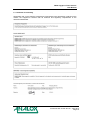
1
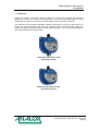
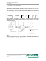
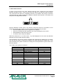
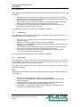
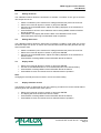
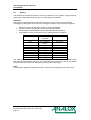
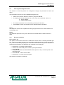
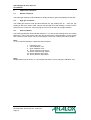
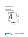
FGD3 Oxygen & Toxic Sensors
User Manual
Analox Ltd.
15 Ellerbeck Court, Stokesley Business Park
North Yorkshire, TS9 5PT, UK
T: +44 (0)1642 711400 F: +44 (0)1642 713900
W: www.analox.net E: [email protected]
FGD3 Oxygen & Toxic Sensors
User Manual
List of Contents
1
2
3
4
5
6
7
8
Introduction..........................................................................................................................3
1.1 Installation......................................................................................................................4
1.1.1
Siting the sensors .................................................................................................4
1.1.2
Wire termination....................................................................................................4
1.1.3
Cable routing.........................................................................................................4
1.1.4
Cable & screening.................................................................................................4
Installation in a non-hazardous location..............................................................................5
2.1 Installation in a hazardous location ...............................................................................6
Menu mode selection ..........................................................................................................7
3.1 Zero sensor....................................................................................................................8
3.2 Sensor span...................................................................................................................8
3.3 Select FSD.....................................................................................................................8
3.4 Setting 4mA level...........................................................................................................9
3.5 Setting 20mA level.........................................................................................................9
3.6 Display mode .................................................................................................................9
3.7 Display firmware version ...............................................................................................9
3.8 Restore ........................................................................................................................10
3.9 View engineer/diagnostics data...................................................................................11
3.10
Set cross reference .................................................................................................11
3.11
Positive zero suppression .......................................................................................12
3.12
Negative zero suppression......................................................................................12
3.13
Password.................................................................................................................13
FGD3 head indications ......................................................................................................14
4.1 Normal conditions ........................................................................................................14
4.2 High gas conditions .....................................................................................................14
4.3 Fault conditions............................................................................................................14
Sensor replacement ..........................................................................................................15
Mounting details ................................................................................................................17
Certification........................................................................................................................18
Certificate of conformity.....................................................................................................19
Document Ref: P0102-807-00 - June 2012
Page 1
FGD3 Oxygen & Toxic Sensors
User Manual
Document Ref: P0102-807-00 - June 2012
Page 2
FGD3 Oxygen & Toxic Sensors
User Manual
1 Introduction
Analox Ltd FGD3 O2 and toxic detector heads are 4-20mA loop powered gas detectors
designed to monitor gas levels in the atmosphere. The sensor type fitted within the head
dictates the gas type to be monitored, and the range to which the head is sensitive.
The detectors use the industry standard 4-20mA current loop to convey the gas levels to a
control unit. This means that under zero gas conditions 4mA is drawn from the supply, and
under full scale gas conditions 20mA is drawn from the supply. The current varies linearly for
gas levels between zero and full scale.
FGD3 Atex gas detector head
with plug-in sensor
FGD3 Atex gas detector head
with internal sensor
Document Ref: P0102-807-00 - June 2012
Page 3
FGD3 Oxygen & Toxic Sensors
User Manual
1.1 Installation
1.1.1
Siting the sensors
Mounting positions for sensors need to be considered individually, some points for
consideration are:
•
•
•
•
•
•
Ensure all sensors are mounted to allow routine calibration and maintenance to be carried
out as required.
Ensure the proposed site will not interfere with movement of existing equipment, e.g.
cranes, doors etc.
Install all cables neatly and securely.
Sensors for detecting gases that are lighter than air should be positioned at a high level.
Sensors for heavier than air gases should be located at below head height.
Avoid siting the sensors adjacent to potential sources of radio frequency interference, e.g.
radio transmitters, control switchgear, motors etc.
1.1.2
Wire termination
All connections should be made according to the appropriate sensor or loop diagram for the
configuration required. It is advised that ‘bootlace ferrules’ or ‘flat blade crimps’ be used for
tidy and reliable connections of wires into the Detector Head connectors.
1.1.3
Cable routing
Due to the low signal levels generated by gas detectors it is recommended that all wiring to
the sensors be segregated away from AC mains or other high voltage/power lines to avoid
interference.
1.1.4
Cable & screening
The use of a screened cable is recommended for the installation of all detector heads. The
correct strategy for connecting the screens depends upon the area in which the detector head
is to be used (i.e. hazardous/ non-hazardous). In all cases the screen should not be
connected at the detector head. Refer to the connection diagrams on the following pages for
further information.
The oxygen and toxic detector heads require a two wire connection to the control unit:
+
current loop to head
current loop return to control unit
Document Ref: P0102-807-00 - June 2012
Page 4
FGD3 Oxygen & Toxic Sensors
User Manual
2
Installation in a non-hazardous location.
When a detector head is installed in an area where there is no potential of an explosive gas
hazard present, the cable lengths to the detector are limited solely by the resistance of the
cable. The FGD3 gas detectors require a minimum of 8V between the Sig and 0V terminals to
allow them to operate correctly.
For systems operating at 24V, the maximum cable loop resistance is therefore (24-8)/25mA
i.e. 640Ω.
0V
Sig
Screen
Note The control unit 0V must be
connected to Earth
The diagram above shows connections for FGD1/2 detector head in a non-hazardous
location. The pin numbers shown at the control unit refer to pin numbers on the input modules
within the MCU control units. Refer to manufacturer if alternative control unit is used.
Document Ref: P0102-807-00 - June 2012
Page 5
FGD3 Oxygen & Toxic Sensors
User Manual
2.1 Installation in a hazardous location
When used in a hazardous area, the FGD3 detector requires an intrinsically safe (I.S.) power
supply. This can be provided by using proprietary safety barriers
The use of barriers to create an I.S. supply imposes certain restrictions on the parameters of
the interconnecting cables used. Consult the barrier manufacturers data for further
information.
Barriers must be selected to restrict the I.S. supply to the gas detectors within the following
parameters:
Gas detector
FGD3 oxygen
or toxic
Terminals
- and +
Umax
30V
Imax
0.15A
Pin
0.81W
Ci
10nF
Li
0
When considering the capacitance and inductance allowable across the barrier output
terminals, there is 10nF capacitance and zero inductance between terminals ‘-‘ and ‘+’ on any
model of FGD detector.
0V
Sig
Screen
Screen
Note The control unit 0V is not
connected to Earth
Hazardous Area
Safe Area
Note:
If an MCU control unit is being used, then the Analox I.S. output module type FGDIO can be
used to provide the necessary I.S. outputs. This module is located within the MCU enclosure,
see P0102-800 MCU 3 & 4 Hardware Manual for details.
Document Ref: P0102-807-00 - June 2012
Page 6
FGD3 Oxygen & Toxic Sensors
User Manual
3 Menu mode selection
In order to gain access to the menu switches and test points, release the screw situated
between the letters A and T of the chrome ‘STATUS’ label on the detector head front panel.
The screw does not need to be completely removed, only release it far enough so that the
‘STATUS’ label can rotate revealing the calibration switches and test points. The buttons and
test points are designated as follows:
V
+
-
UP DOWN TP1 TP2 ENTER MENU
Several calibration modes exist in the detector head and these are accessible via the
instruments simple menu system. To select a menu mode follow this procedure:
• Press the MENU button and C: 1 appears on the display.
• Press UP or DOWN until the required menu mode is displayed on the screen.
• Press ENTER to select the menu mode.
• To exit the menu mode press MENU.
While the instrument is in a menu mode – any data displayed on the screen will alternate
between the menu number and the reading.
If the password is set the user will be prompted with PASS when the MENU key is pressed.
The user has the option of ignoring the password by simply pressing the MENU key, in this
case a limited menu system is offered or entering the correct password to gain access to the
full menu options.
The ‘FGD3’ menu system is as follows: Cal number
1
2
3
4
5
6
7
8
9
12
19
20
30
Function
Zero sensor
Sensor span
Select FSD
Setting 4mA level
Setting 20mA level
Display mode
Display firmware version
Restore
View engineer/diagnostics
data
Set cross reference
Positive zero suppression
Negative zero suppression
Password
Section
3.1
3.2
3.3
3.4
3.9
3.10
3.7
3.8
3.9
3.10
3.11
3.12
3.13
Document Ref: P0102-807-00 - June 2012
Page 7
FGD3 Oxygen & Toxic Sensors
User Manual
3.1
Zero sensor
This calibration feature allows the instrument to determine the sensor output under zero gas
conditions.
•
•
•
•
Apply zero gas to the sensor inlet and allow enough time for the sensor to respond
and all the gas to be purged (typically 2 minutes minimum dependent upon flow rate).
Select menu mode C: 1 and press ENTER.
Press ENTER to perform the ZERO calibration. Pressing MENU instead of ENTER
aborts the calibration (the ZERO factor will still be displayed on exit).
Press MENU – the display will show the ZERO factor for the instrument before
returning to its standard mode of operation.
The ZERO factor should be recorded on any calibration certificates.
3.2
Sensor span
This calibration feature allows the instrument to determine the sensor output when it is
exposed to a know concentration of gas.
•
•
•
•
•
Apply a known concentration of gas to the sensor inlet and allow enough time for the
sensor to respond.
Select menu mode C: 2 (refer to section 3) and press ENTER.
Using the UP and DOWN buttons, adjust the displayed reading so that it matches the
calibration gas concentration.
Press ENTER to perform the SPAN calibration. Pressing MENU instead of ENTER
aborts the calibration (the SPAN factor will still be displayed on exit).
Press MENU – the display will show the SPAN factor for the instrument before
returning to its standard mode of operation.
The SPAN factor should be recorded on any calibration certificates.
3.3
Select FSD
The FSD value is usually matched to the sensor fitted. If the sensor is say a 0 to 20 ppm
chlorine sensor then the FSD is set to 20. It is possible to transmit a lower range on the 4 to
20 mA signal by reducing this value to say 10 ppm.
This function does not affect the sensor calibration but does change the maximum reading
that can be measured.
Note:
Changing this value outside the sensor’s operating range may make the FGD3 unsuitable for
its intended use.
•
•
•
•
Select menu mode C: 3 (refer to section 3) and press ENTER.
Using the UP and DOWN buttons, adjust the displayed reading until the desired
setting is displayed.
Press ENTER to save the setting. Pressing MENU instead of ENTER aborts the
calibration (the sensor FSD factor will still be displayed on exit).
Press MENU – the display will show the sensor FSD for the instrument before
returning to its standard mode of operation.
Document Ref: P0102-807-00 - June 2012
Page 8
FGD3 Oxygen & Toxic Sensors
User Manual
3.4
Setting 4mA level
This calibration feature allows the instrument to simulate a condition of zero gas so that the
4mA output can be set.
•
•
•
•
•
3.5
Attach a multimeter (set to measure DC voltage) between test points TP1 and TP2.
Select menu mode C: 4 (refer to section 3) and press ENTER.
Using the UP and DOWN buttons, adjust the reading displayed on the multimeter to
40mV ±0.5mV
Press ENTER to store the 4mA calibration data. Pressing MENU instead of ENTER
aborts the feature.
Press MENU – the display will show the DAC 4mA calibration factor for the
instrument before returning to its standard mode of operation.
Setting 20mA level
This calibration feature allows the instrument to simulate a condition of full-scale gas so that
the 20mA output can be set. A control unit connected will indicate full-scale gas also and may
enter its alarm state.
•
•
•
•
3.6
Attach a multimeter (set to measure DC voltage) between test points TP1 and TP2.
Select menu mode C: 5 (refer to section 3) and press ENTER.
Using the UP and DOWN buttons, adjust the reading displayed on the multimeter to
200mV ±0.5mV
Press ENTER. Pressing MENU instead of ENTER aborts the feature.
Display mode
•
•
•
•
Select menu mode C: 6 (refer to section 3) and press ENTER.
Use the UP and DOWN button to move the decimal point to the desired setting.
Press ENTER. Pressing MENU instead of ENTER aborts the feature.
Press MENU to return the instrument to its standard mode of operation.
Note:
Changing the decimal point will not result in a more accurate reading.
3.7
Display firmware version
The firmware version is displayed as part of the start up procedure but can be viewed without
powering down the instrument via menu option 7.
•
•
•
•
Select menu mode C: 7 (refer to section 3) and press ENTER.
The display will show the firmware version number.
Press ENTER. Pressing MENU instead of ENTER aborts the feature.
Press MENU to return the instrument to its standard mode of operation.
Document Ref: P0102-807-00 - June 2012
Page 9
FGD3 Oxygen & Toxic Sensors
User Manual
3.8
Restore
The firmware for the detector head is common to infrared CO2, HC, pellistor, oxygen and toxic
instruments. This feature allows the type of sensor fitted to be selected.
Important
The instrument supplied with this manual has either an oxygen or toxic sensor installed.
Changing the setting within this menu will not change the gas to which the sensor responds.
•
•
•
•
Select menu mode C: 8 (refer to section 3) and press ENTER.
Use the UP button to toggle the sensor type (see table below)
Press ENTER. Pressing MENU instead of ENTER aborts the feature.
Press MENU to return the instrument to its standard mode of operation.
Sensor type
O2-1
O2-2
O2-3
Elt1
Elt2
Elt3
Elt4
Elt5
Elt6
Elt7
Elt8
Range
0 to 25%vol
non linear
0 to 25%vol linear
0 to 1000ppm
linear
5 ppm
10 ppm
20 ppm
50 ppm
200 ppm
500 ppm
1000 ppm
9999 ppm
display
0.0 to 20.9
0.0 to 20.9
0 to 1000
0.0 to 5.0
0.0 to 10.0
0.0 to 20.0
0.0 to 50.0
0 to 200
0 to 500
0 to 1000
0 to 9999
This feature will erase all the configuration settings of the detector head and replace them
with the instruments default values for the sensor selected. Following the use of this feature
the instrument must have a full calibration (including the 4-20mA loop).
Note:
A linearization algorithm is applied to the O2-1 sensor type as supplied by City Technology.
Document Ref: P0102-807-00 - June 2012
Page 10
FGD3 Oxygen & Toxic Sensors
User Manual
3.9
View engineer/diagnostics data
This feature is a view-only feature. No configuration changes are possible from within this
menu.
This information is for the use of the installation engineer only.
•
•
Select menu mode C: 9 (refer to section 3) and press ENTER.
The display will alternate between the current value and code C: 9x: where x is:
0 Sensor reading.
4 Detector AtoD counts.
•
•
The mode of operation can be selected by pressing the UP button.
Press MENU to return the instrument to its standard mode of operation.
Note1:
The diagnostic structure is compatible with other gas types and as such certain features are
not available, N/A.
Note2:
The diagnostic option 95 is only of use where a four electrode electro-chemical sensor is
fitted.
3.10
Set cross reference
Menu mode C: 12
This option is used to allow the user to calibrate the sensor with a commonly available gas
(e.g. methane or propane) but use the unit to detect a different gas (e.g. methanol or acetone
etc.). This is achieved by adjusting the cross-reference factor according to the difference in
signal that is detected for the calibration gas compared to the target gas.
•
•
•
•
Press button 1 to open the menu system.
Select menu mode C:12 (refer to section 3) and press ENTER.
Press ENTER.
Using the INCREASE and DECREASE buttons (buttons 3 & 4), set the required crossreference factor.
• Press ENTER to store the new value.
• Press button 1 to close the menu system.
Ask Analox Ltd for advice on settings.
Document Ref: P0102-807-00 - June 2012
Page 11
FGD3 Oxygen & Toxic Sensors
User Manual
3.11
Positive zero suppression
This option is used to allow the user to suppress small amounts of positive sensor zero drift.
The setting can be set between 0 and 10% of the sensor range as set by the FSD value.
•
•
•
•
•
Press MENU to open the menu system.
Using the NEXT and PREVIOUS buttons, select menu option: E:19
Press ENTER.
Using the INCREASE and DECREASE buttons, set the required zero
suppression value.
Press ENTER to store the new value.
Note:
Pressing the MENU button rather than the ENTER button exits without any change.
•
3.12
Press MENU to close the menu system.
Negative zero suppression
This option is used to allow the user to suppress small amounts of negative sensor zero drift.
The setting can be set between 0 and 10% of the sensor range as set by the FSD value.
•
•
•
•
•
Press MENU to open the menu system.
Using the NEXT and PREVIOUS buttons, select menu option: E:20
Press ENTER.
Using the INCREASE and DECREASE buttons, set the required zero
suppression value.
Press ENTER to store the new value.
Note:
Pressing the MENU button rather than the ENTER button exits without any change.
•
Press MENU to close the menu system.
Document Ref: P0102-807-00 - June 2012
Page 12
FGD3 Oxygen & Toxic Sensors
User Manual
3.13
Password
This option is used to allow the user to limit the option available for users by means of a
password.
•
•
•
•
•
Press MENU to open the menu system.
Using the NEXT and PREVIOUS buttons, select menu option: E:30
Press ENTER.
Using the up button, toggle the display between OFF & On.
Press ENTER to store the new value.
Note:
Pressing the MENU button rather than the ENTER button exits without any change.
•
Press MENU to close the menu system.
Note:
If the password should be obtained from Analox Ltd before selecting the ‘On’ setting.
The password limits the user to menu options 1,2,4 and 5.
Document Ref: P0102-807-00 - June 2012
Page 13
FGD3 Oxygen & Toxic Sensors
User Manual
4
FGD3 head indications
4.1
Normal conditions
The FGD3 gas detector head will display a steady reading for gas levels between 0 and FSD.
4.2
High gas conditions
The FGD3 gas detector head will flash between the gas reading and ‘Hi ’ when the gas
reading is above the sensor FSD. This will coincide with the head drawing a current of 20 to
25mA from the control unit, thus ensuring the control unit is aware of the high condition.
4.3
Fault conditions
The FGD3 gas detector head will flash between ‘F xx’ and the gas reading when the reading
falls below –10% of the sensor FSD. This will coincide with the head drawing a current of less
than 2.5mA from the control unit, thus ensuring the control unit is aware of the fault condition.
Note:
‘xx’ is a number that defines a particular fault as follows:
1
2
4
8
16
32
64
Checksum error.
Zero calibration error.
Span calibration error.
Sensor reference low output.
Sensor reference high output.
Sensor detector low output.
Sensor detector high output.
Note:
Multiple faults may be shown i.e. F:6 indicates that there is a zero and span calibration error.
Document Ref: P0102-807-00 - June 2012
Page 14
FGD3 Oxygen & Toxic Sensors
User Manual
5
Sensor replacement
Note:
Applies only to instruments fitted with an integral sensor.
Arrangement ( A )
a)
b)
c)
d)
e)
f)
g)
h)
i)
Inhibit the channel at the control unit.
Disconnect power to the head at the control unit.
Release the sensor retainer.
Unplug the sensor from the PCB.
Push the new sensor into the PCB, making sure of the pin alignment.
Refit the sensor retainer.
Allow the sensor to stabilise for 1 to 2 hours prior to calibration.
Calibrate the detector head.
Enable the channel at the control unit.
Sensor
Sensor retainer
Document Ref: P0102-807-00 - June 2012
Page 15
FGD3 Oxygen & Toxic Sensors
User Manual
Arrangement ( B )
a) Inhibit the channel at the control unit.
b) Disconnect power to the head at the control unit.
c) Release sensor housing by undoing the locking ring or splashguard adaptor
depending upon which is fitted.
d) Unscrew the two M4 screws of the terminal box chassis and remove.
e) Remove the sensor housing from the detector.
f) Unscrew the four countersunk screws from the sensor housing cover plate to reveal
the sensor.
g) Remove the sensor and replace with the new sensor, taking note of the wire positions
and colour codes.
h) Replace the cover plate and tighten the four screws.
i) Replace the sensor housing locking ring or splashguard adaptor.
j) Refit the terminal box chassis to the instrument.
k) Allow the sensor to stabilise for 1 to 2 hours prior to calibration.
l) Calibrate the detector head.
m) Enable the channel at the control unit.
Terminal box chassis
Sensor housing
Splashguard adaptor
Locking ring
Document Ref: P0102-807-00 - June 2012
Page 16
FGD3 Oxygen & Toxic Sensors
User Manual
6
Mounting details
The diagram below shows the mounting centres for the FGD detector head enclosure.
122
102
102
122
140
Depth = 75mm approx
Note:
The front panel/lid of the detector head opens to allow access to the screw terminals situated
inside. Sufficient space should be allowed around the mounting position so that this action is
not restricted.
Fixings required:
2 off M6 fasteners
(Rawl bolts or similar dependent on mounting wall construction)
Document Ref: P0102-807-00 - June 2012
Page 17
FGD3 Oxygen & Toxic Sensors
User Manual
7 Certification
The FGD oxygen and toxic gas detectors carry the following markings:
Document Ref: P0102-807-00 - June 2012
Page 18
FGD3 Oxygen & Toxic Sensors
User Manual
8 Certificate of conformity
We declare that, on the date the equipment accompanied by this declaration is placed on the
market, the equipment conforms with all technical and regulatory requirements of the
directives listed below.
Document Ref: P0102-807-00 - June 2012
Page 19