1
E6581597 1
Safety
precautions
ᑄ᫈ߦߟߡߩ
߅㗿
එ̩̠̤̞̩̺̯̞৾ͤࠗͣ͢
̭͈৾ե୰ྶ͉ȂषͅͼϋΨȜΗ̮ͬঀဥ༷͈̤̈́ͥͅࡓͅຈ̴
Introduction
ȽȁΓΛΠιȜအ͒ȁȽ
⸽ߦߟߡ
̴༗ం̱̩̺̯̞̀ȃ
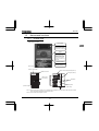
TOSVERT VF-nC3
ขᛒ⺑ᦠ
̭͈ȶ৾ե୰ྶȷ̩̤ͬ͢උ͙̩̺̯̞ȃ̤උ͙̹̜͉̈́̽͂ͅȂຈ
Contents
Industrial Inverter
Read first
(For 3-phase induction motors)
Industrial Inverter
Connection
Operations
Instruction Manual
TM
TOSVERT
VF-nC3
< Simplified manual >
TOSVERT VF-nC3 Instruction Manual
↥ᬺ↪ࠗࡦࡃ䳦࠲
I
II
Setting
parameters
Main
parameters
Other
parameters
Operation
with external
signal
Monitoring the
operation status
Measures
to satisfy the
standards
1-phase 120V class 0.1 to 0.75kW
1-phase 240V class 0.1 to 2.2kW
3-phase 240V class 0.1 to 4kW
Peripheral
devices
Table of
parameters
and data
Specifications
Before making
a service call
NOTICE
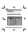
1.Make sure that this instruction manual is delivered to the
end user of the inverter unit.
2.Read this manual before installing or operating the inverter
unit, and store it in a safe place for reference.
Inspection and
maintenance
Warranty
Disposal of the
inverter
1
2
3
4
5
6
7
8
9
10
11
12
13
14
15
16
̤ͼ͈͛ݥϋΨȜΗͬୃ̱̩ঀ̞̹̺̩̹̽̀͛ͅȂ̤ঀ̞̈́ͥͅஜͅ
̠̮̰̞̳͘ȃ
ߗ߭ὐᬌࠍ
ࠨࡆࠬࠦ࡞
ࠍߔࠆ೨ߦ
̭͈̹͍͉ঢ়ॲުဥͼϋΨȜΗ̤ͬฃ̞ષ̧̬̞̹̺̱̜̦̀ͤ͂͘
ᯏེߩ᭽
ࡄࡔ࠲৻ⷩ㧛
࠺࠲
න⋧ޓ100V ࠢࠬ 0.1㨪0.75kW
න⋧ޓ200V ࠢࠬ 0.1㨪2.2kW
ਃ⋧ޓ200V ࠢࠬ 0.1㨪3.7kW
ㆡวኈ㊂ᯏ⒳
ㄝᯏེߩㆬቯ
ฦ⒳ⷙᩰ
߳ߩኻᔕ
ㆇォ⁁ᘒࠍ
ࡕ࠾࠲ߔࠆ
TOSVERTTM
VF-nC3
◲නዊᒻࠗࡦࡃ࠲
ขޓᛒޓ⺑ޓᦠޓ
ᄖㇱାภߢㆇォ
ߒߚߣ߈
ߘߩઁߩࡄࡔ࠲
ߩ⺑
ਥߥࡄࡔ࠲
ߩ⺑
ࡄࡔ࠲ߩ
⸳ቯᣇᴺ
ㆇォߩߒ߆ߚ
ᯏེߩធ⛯
㧔ਃ⋧⺃ዉ㔚േᯏ↪㧕
↥ᬺ↪ࠗࡦࡃ࠲
߹ߕ߅⺒ߺ
ߊߛߐ
1
2
3
4
5
6
7
8
9
10
11
12
13
14
15
16
⋡ᰴ
ߪߓߦ
ోߩߏᵈᗧ
E6581596Ԙ
I
II
E6581597
I.
I
Safety precautions
The items described in these instructions and on the inverter itself are very important so that you can use the
inverter safely, prevent injury to yourself and other people around you as well as to prevent damage to property in
the area. Thoroughly familiarize yourself with the symbols and indications shown below and then continue to read
the manual. Make sure that you observe all warnings given.
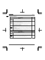
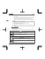
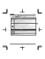
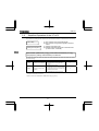
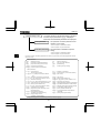
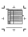
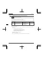
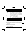
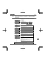
Explanation of markings
Marking
Meaning of marking
Warning
Indicates that errors in operation may lead to death or serious injury.
Caution
Indicates that errors in operation may lead to injury (*1) to people or that these errors may
cause damage to physical property. (*2)
(*1) Such things as injury, burns or shock that will not require hospitalization or long periods of outpatient
treatment.
(*2) Physical property damage refers to wide-ranging damage to assets and materials.
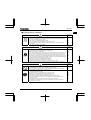
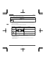
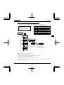
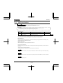
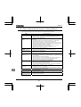
Meanings of symbols
Marking
Meaning of marking
Indicates prohibition (Don't do it).
What is prohibited will be described in or near the symbol in either text or picture form.
Indicates an instruction that must be followed.
Detailed instructions are described in illustrations and text in or near the symbol.
-Indicates warning.
What is warned will be described in or near the symbol in either text or picture form.
-Indicates caution.
What the caution should be applied to will be described in or near the symbol in either text or picture form.
Limits in purpose
This inverter is used for controlling speeds of three-phase induction motors in general industrial use.
Single-phase power input is output by the inverter as 3-phase output and cannot drive a single-phase motor.
Safety precautions
The inverter cannot be used in any device that would present danger to the human body or from which
malfunction or error in operation would present a direct threat to human life (nuclear power control
device, aviation and space flight control device, traffic device, life support or operation system, safety
device, etc.). If the inverter is to be used for any special purpose, first get in touch with the supplier.
This product was manufactured under the strictest quality controls but if it is to be used in critical
equipment, for example, equipment in which errors in malfunctioning signal output system would cause
a major accident, safety devices must be installed on the equipment.
Do not use the inverter for loads other than those of properly applied three-phase induction motors in
general industrial use. (Use in other than properly applied three-phase induction motors may cause an
accident.)
1
E6581597
I
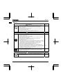
General Operation
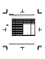
Warning
Reference
section
Never disassemble, modify or repair.
This can result in electric shock, fire and injury. For repairs, call your sales distributor.
2.
Do not open the terminal block cover while the inverter is on.
The unit contains many high voltage parts and contact with them will result in electric shock.
Do not stick your fingers into openings such as cable wiring holes and cooling fan covers.
This can result in electric shock or other injury.
Do not place or insert any kind of object into the inverter (electrical wire cuttings, rods, wires
etc.).
This can result in electric shock or fire.
Do not allow water or any other fluid to come in contact with the inverter.
This can result in electric shock or fire.
After replacing the terminal block cover, turn the input power on.
Turning on the input power without replacing the terminal block cover may lead to electric
shock.
If the inverter begins to emit smoke or an unusual odor, or unusual sounds, immediately
turn power off.
If the equipment is continued in operation in such a state, the result may be fire. Call your
local sales agency for repairs.
Always turn power off if the inverter is not used for long periods of time since there is a
possibility of malfunction caused by leaks, dust and other material. If power is left on with
the inverter in that state, it may result in fire.
2.1
Disassembly
prohibited
Prohibited
Mandatory
action
Caution
Do not touch heat radiating fins or discharge resistors.
These devices are hot, and you'll get burned if you touch them.
2.
2.
2.
2.1
3.
3.
Reference
section
3.
Contact
prohibited
Mandatory
action
Use an inverter that conforms to the specifications of power supply and three-phase
induction motor being used. If the inverter being used does not conform to those
specifications, not only will the three-phase induction motor not rotate correctly, it
may also cause serious accidents through overheating and fire.
2
1.1
E6581597
I
Transportation & installation
Warning
Prohibited
Do not install or operate the inverter if it is damaged or any component is missing.
This can result in electric shock or fire. Please consult your local sales agency for repairs.
Call your local sales agency for repairs.
Do not place any inflammable objects nearby.
If a flame is emitted due to malfunction, it may result in a fire.
Do not install in any location where the inverter could come into contact with water or
other fluids.
This can result in electric shock or fire.
Warning
Mandatory
action
Must be used in the environmental conditions prescribed in the instruction manual.
Use under any other conditions may result in malfunction.
Mount the inverter on a metal plate.
The rear panel gets very hot. Do not install in an inflammable object, this can result in fire.
Do not use the inverter without the terminal block cover. This can result in electric shock.
Failure to do so can lead to risk of electric shock and can result in death or serious injury.
An emergency stop device must be installed that fits with system specifications (e.g. shut
off input power then engage mechanical brake). Operation cannot be stopped immediately
by the inverter alone, thus risking an accident or injury.
All options used must be those specified by Toshiba.
The use of any other option may result in an accident.
When using switchgear for the inverter, it must be installed in a cabinet.
Failure to do so can lead to risk of electric shock and can result in death or serious injury.
Caution
Prohibited
Mandatory
action
When transporting or carrying, do not hold by the front panel covers.
The covers may come off and the unit will drop out resulting in injury.
Do not install in any area where the unit would be subject to large amounts of vibration.
That could result in the unit falling, resulting in injury.
When removing and installing the terminal cover with a screwdriver, be sure not to scratch
your hand as this results in injury.
Pressing too hard on the screwdriver may scratch the inverter.
Always cut the power supply when removing the wiring cover.
After wiring is complete, be sure to replace the terminal cover.
The main unit must be installed on a base that can bear the unit's weight.
If the unit is installed on a base that cannot withstand that weight, the unit may fall
resulting in injury.
If braking is necessary (to hold motor shaft), install a mechanical brake.
The brake on the inverter will not function as a mechanical hold, and if used for that
purpose, injury may result.
3
Reference
section
1.4.4
1.4.4
1.4.4
Reference
section
1.4.4
1.4.4
1.4.4
1.4.4
1.4.4
10
Reference
section
2.
1.4.4
1.3.2
1.3.2
1.3.2
1.3.2
1.4.4
1.4.4
E6581597
I
Wiring
Warning
Prohibited
Do not connect input power to the output (motor side) terminals (U/T1,V/T2,W/T3).
That will destroy the inverter and may result in fire.
Do not connect resistors to the DC terminals (across PA/+ - PC/- or PO-PC/-).
That may cause a fire.
Within 15 minutes after turning off input power, do not touch wires of devices (MCCB)
connected to the input side of the inverter.
That could result in electric shock.
When supplying power from a wall socket, do not exceed the rated capacity of the socket.
Otherwise, this may generate excessive heat which can start a fire.
Warning
Mandatory
action
Electrical installation work must be done by a qualified expert.
Connection of input power by someone who does not have that expert knowledge may
result in fire or electric shock.
Connect output terminals (motor side) correctly.
If phase sequence is incorrect, motor will operate in reverse and that may result in injury.
Wiring must be done after installation.
If wiring is done prior to installation that may result in injury or electric shock
The following steps must be performed before wiring.
(1) Turn off all input power.
(2) Wait at least 15 minutes and check to make sure that the charge lamp is no longer lit.
(3) Use a tester that can measure DC voltage (400VDC or more), and check to make sure
that the voltage to the DC main circuits (across PA/+ - PC/-) is 45V or less.
If these steps are not properly performed, the wiring will cause electric shock.
Tighten the screws on the terminal board to specified torque.
If the screws are not tightened to the specified torque, it may lead to fire.
Check to make sure that the input power voltage is +10%, -15% of the rated power
voltage written on the rating label (±10% when the load is 100% in continuous operation).
If the input power voltage is not +10%, -15% of the rated power voltage (±10% when the
load is 100% in continuous operation) this may result in fire.
Set a parameter f109 when VIA or VIB terminals are used as logic input terminal.
If it is not set, it could result in malfunction.
Ground must be connected securely.
If the ground is not securely connected, it could lead to electric shock or fire when a
malfunction or current leak occurs.
Reference
section
2.2
2.2
2.2
10.
Reference
section
2.1
2.1
2.1
2.1
2.1
1.4.4
2.2
2.1
2.2
10.
Be Grounded
Caution
Prohibited
Do not attach equipment (such as noise filters or surge absorbers) that have built-in
capacitors to the output (motor side) terminals.
That could result in a fire.
4
Reference
section
2.1
E6581597
Warning
Configuring settings on the setup menu incorrectly may break the inverter or lead to
malfunction.
Reference
section
3.1
Mandatory
action
Operations
Warning
Never touch the internal terminals in the upper right while the front cover is open.
There is a risk of shock because it carries a high voltage.
Reference
section
1.3.1
Prohibited
Warning
Prohibited
Mandatory
action
Do not touch inverter terminals when electrical power is going to the inverter even if the
motor is stopped.
Touching the inverter terminals while power is connected to it may result in electric shock.
Do not touch switches when the hands are wet and do not try to clean the inverter with a
damp cloth.
Such practices may result in electric shock.
Do not go near the motor in alarm-stop status when the retry function is selected.
The motor may suddenly restart and that could result in injury.
Take measures for safety, e.g. attaching a cover to the motor, against accidents when the
motor unexpectedly restarts.
After replacing the terminal block cover, turn the input power on.
When installed inside a cabinet and using with the front cover removed, always close the
cabinet doors first and then turn power on. Turning on the power with the terminal block
cover or cabinet doors open may result in electric shock.
Make sure that operation signals are off before resetting the inverter after malfunction.
If the inverter is reset before turning off the operating signal, the motor may restart
suddenly causing injury.
Caution
Prohibited
Mandatory
action
Observe all permissible operating ranges of motors and mechanical equipment. (Refer to
the motor's instruction manual.)
Not observing these ranges may result in injury.
Do not set the stall prevention level () extremely low.
If the stall prevention level parameter () is set at or below the no-load current of
the motor, the stall preventive function will be always active and increase the frequency
when it judges that regenerative braking is taking place.
Do not set the stall prevention level parameter () below 30% under normal use.
Use an inverter that conforms to the specifications of power supply and three-phase
induction motor being operated. If the inverter being used does not conform to those
specifications, not only will the three-phase induction motor not rotate correctly, but it may
cause serious accidents through overheating and fire.
Current may leak through the inverter's input/output wires because of insufficient
electrostatic capacity on the motor with bad effects on peripheral equipment.
The leakage current’s value is affected by the carrier frequency and the length of the
input/output wires. Test and adopt the remedies of section 1.4.3 against leak current.
5
Reference
section
3.
3.
3.
3.
3.
Reference
section
3.
6.16.2
1.4.1
1.4.3
I
E6581597
I
When operation by using remote keypad is selected
Warning
Mandatory
action
Set the parameter Communication time-out time (f803) and Communication time-out
action (f804).
If these are not properly set, the inverter can not be stopped immediately in breaking
communication and this could result in injury and accidents.
An emergency stop device and the interlock that fit with system specifications must be
installed.
If these are not properly installed, the inverter can not be stopped immediately and this
could result in injury and accidents.
Reference
section
E6581595,
6.19
When sequence for restart after a momentary failure is selected (inverter)
Caution
Mandatory
action
Stand clear of motors and mechanical equipment.
If the motor stops due to a momentary power failure, the equipment will start suddenly
after power recovers. This could result in unexpected injury.
Attach caution label about sudden restart after a momentary power failure on inverters,
motors and equipment for prevention of accidents in advance.
Reference
section
E6581595,
6.12.1
E6581595,
6.12.1
When retry function is selected (inverter)
Caution
Mandatory
action
Stand clear of motors and equipment.
If the motor and equipment stop when the alarm is given, selection of the retry function will
restart them suddenly after the specified time has elapsed. This could result in unexpected
injury.
Attach caution label about sudden restart in retry function on inverters, motors and
equipment for prevention of accidents in advance.
Reference
section
E6581595,
6.12.3
E6581595,
6.12.3
Maintenance and inspection
Warning
Prohibited
Mandatory
action
Reference
section
Do not replace parts.
This could be a cause of electric shock, fire and bodily injury. To replace parts, call the
local sales agency.
14.2
The equipment must be inspected every day.
If the equipment is not inspected and maintained, errors and malfunctions may not be
discovered and that could result in accidents.
Before inspection, perform the following steps.
(1) Turn off all input power to the inverter.
(2) Wait at least 15 minutes and check to make sure that the charge lamp is no longer lit.
(3) Use a tester that can measure DC voltages (400VDC or more), and check to make
sure that the voltage to the DC main circuits (across PA/+ - PC/-) is 45V or less.
If inspection is performed without performing these steps first, it could lead to electric
shock.
14.
6
14.
14.2
E6581597
I
Disposal
Caution
Mandatory
action
If you dispose of the inverter, have it done by a specialist in industry waste disposal(*).
If you dispose of the inverter in an inappropriate way, this can result in explosion of
capacitor or produce noxious gases, resulting in injury.
(*) Persons who specialize in the processing of waste and known as "industrial waste
product collectors and transporters" or "industrial waste disposal persons. "If the
collection, transport and disposal of industrial waste is done by someone who is not
licensed for that job, it is a punishable violation of the law. (Laws in regard to cleaning
and processing of waste materials)
Reference
section
16.
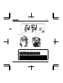
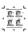
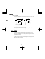
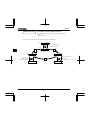
Attach caution labels
Shown here are examples of warning labels to prevent, in advance, accidents in relation to inverters, motors and other
equipment.
Be sure to affix the caution label where it is easily visible when selecting the auto-restart function (6.12.1) or the retry
function (6.12.3).
If the inverter has been programmed for restart
sequence of momentary power failure, place warning
labels in a place where they can be easily seen and
read.
(Example of caution label)
If the retry function has been selected, place warning
labels in a location where they can be easily seen and
read.
(Example of caution label)
Caution (Functions
programmed for retry)
Caution (Functions
programmed for restart)
Do not go near motors and equipment.
Motors and equipment that have stopped
temporarily after an alarm will restart suddenly
after the specified time has elapsed.
Do not go near motors and equipment.
Motors and equipment that have stopped
temporarily after momentary power failure will
restart suddenly after recovery.
7
E6581597
II
II. Introduction
Thank you for your purchase of the Toshiba "TOSVERT VF-nC3” industrial inverter.
This instruction manual is for the Ver. 106 or later CPU of the inverter.
Please be informed that CPU version will be frequently upgraded.
8
E6581597
Contents
I
Safety precautions......................................................................................................................................................... 1
II
Introduction.................................................................................................................................................................... 8
1. Read first ....................................................................................................................................................................... A-1
1.1
Check product purchase.................................................................................................................................... A-1
1.2
Contents of the product ..................................................................................................................................... A-2
1.3
Names and functions......................................................................................................................................... A-3
1.4
Notes on the application .................................................................................................................................... A-12
2. Connection .................................................................................................................................................................... B-1
2.1
Cautions on wiring ............................................................................................................................................. B-1
2.2
Standard connections ........................................................................................................................................ B-3
2.3
Description of terminals ..................................................................................................................................... B-6
3. Operations ..................................................................................................................................................................... C-1
3.1
How to Set the Setup Menu............................................................................................................................... C-2
3.2
Simplified Operation of the VF-nC3 ................................................................................................................... C-4
3.3
How to operate the VF-nC3 ............................................................................................................................... C-9
3.4
Meter setting and adjustment ............................................................................................................................ C-13
3.5
Setting the electronic thermal ............................................................................................................................ C-16
3.6
Preset-speed operation (speeds in 15 steps) .................................................................................................... C-21
4. Setting parameters ........................................................................................................................................................ D-1
4.1
Setting and Display Modes ................................................................................................................................ D-1
4.2
How to set parameters....................................................................................................................................... D-3
4.3
Functions useful in searching for a parameter or changing a parameter setting................................................ D-7
4.4
Checking the region settings selection .............................................................................................................. D-12
4.5
EASY key function ............................................................................................................................................. D-13
5. Main parameters............................................................................................................................................................ E-1
6. Other parameters........................................................................................................................................................... F-1
7. Operations with external signal...................................................................................................................................... G-1
8. Monitoring the operation status...................................................................................................................................... H-1
8.1
Flow of status monitor mode.............................................................................................................................. H-1
8.2
Status monitor mode.......................................................................................................................................... H-2
8.3
Display of trip information .................................................................................................................................. H-6
i
E6581597
9. Measures to satisfy the standards..................................................................................................................................I-1
9.1
How to cope with the CE directive......................................................................................................................I-1
9.2
Compliance with UL Standard and CSA Standard..............................................................................................I-5
10. Peripheral devices..........................................................................................................................................................J-1
10.1 Selection of wiring materials and devices ..........................................................................................................J-1
10.2 Installation of a magnetic contactor....................................................................................................................J-3
10.3 Installation of an overload relay..........................................................................................................................J-4
10.4 Optional external devices...................................................................................................................................J-5
11. Table of parameters and data.........................................................................................................................................K-1
11.1 User parameters ................................................................................................................................................K-1
11.2 Basic parameters ...............................................................................................................................................K-1
11.3 Extended parameters.........................................................................................................................................K-4
11.4 Default settings by inverter rating.......................................................................................................................K-15
11.5 Default settings by setup menu ..........................................................................................................................K-15
11.6 Input Terminal Function......................................................................................................................................K-16
11.7 Output Terminal Function ...................................................................................................................................K-19
12. Specifications .................................................................................................................................................................L-1
12.1 Models and their standard specifications ...........................................................................................................L-1
12.2 Outside dimensions and mass ...........................................................................................................................L-4
13. Before making a service call - Trip information and remedies........................................................................................M-1
13.1 Trip causes/warnings and remedies...................................................................................................................M-1
13.2 Restoring the inverter from a trip........................................................................................................................M-6
13.3 If the motor does not run while no trip message is displayed.............................................................................M-7
13.4 How to determine the causes of other problems ................................................................................................M-8
14. Inspection and maintenance ..........................................................................................................................................N-1
14.1 Regular inspection .............................................................................................................................................N-1
14.2 Periodical inspection ..........................................................................................................................................N-2
14.3 Making a call for servicing..................................................................................................................................N-4
14.4 Keeping the inverter in storage ..........................................................................................................................N-4
15. Warranty.........................................................................................................................................................................O-1
16. Disposal of the inverter ..................................................................................................................................................P-1
ii
E6581597
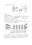
1. Read first
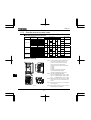
1.1
Check product purchase
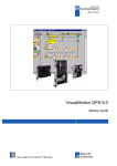
Before using the product you have purchased, check to make sure that it is exactly what you ordered.
1
Caution
Mandatory
action
Use an inverter that conforms to the specifications of power supply and three-phase induction
motor being used. If the inverter being used does not conform to those specifications, not only will
the three-phase induction motor not rotate correctly, it may also cause serious accidents through
overheating and fire.
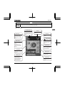
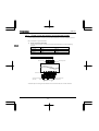
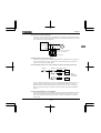
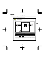
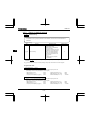
Rating label
Inverter main unit
Brand name
Model
Power supply
Motor capacity
VF-nC3
3PH-200V 0.75kW
Danger label
Carton box
Name plate
Danger label
Name plate
Inverter Type
Inverter rated
output capacity
Power supply
Type indication label
Related input
current
Setup sheet
Related output
current
TRANSISTOR INVERTER
VFNC3S-2022PL
2.2kW-4.1kVA-3HP
(1)
INPUT
OUTPUT
U(V) 1PH 200/240 3PH 200/240
F(Hz)
50/60
0.1/400
21.9/18.4
10.0
I(A)
S.Ckt 1000A FUSE CC/J 30Amax
Serial No. 1328 02021208 0001
Made in . . . . .
Motor Overload Protection Class 10
TSIJ
A-1
E6581597
Instruction manual
E6581597
CD-ROM
Danger label kit
Contains the instruction manual in
digital form
Danger labels for sticking in 6 languages
WARNING
DANGER
ADVERTENCIA
Risk of injury, electric shock or fire.
Read the instruction manual.
Do not open the cover while power is applied
or for 15 minutes after power has been removed.
Ensure proper earth connection.
1
DANGER
Risk of injury, electric shock or fire.
Read the instruction manual. Ensure proper earth connection.
Do not open the cover while power is applied
or for 15 minutes after power has been removed.
WARNUNG
DANGER
Risk of injury, electric shock or fire.
Read the instruction manual. Ensure proper earth connection.
Do not open the cover while power is applied
or for 15 minutes after power has been removed.
AVVERTENZA
DANGER
Risk of injury, electric shock or fire.
Read the instruction manual. Ensure proper earth connection.
Do not open the cover while power is applied
or for 15 minutes after power has been removed.
1.2
⼊ޓ๔
DANGER
Risk of injury, electric shock or fire.
Read the instruction manual. Ensure proper earth connection.
Do not open the cover while power is applied
or for 15 minutes after power has been removed.
AVERTISSEMENT
Risque de blessure, d’électrocution ou d’incendie.
Lire le manuel d’instruction.
Avant d’intervenir dans le variateur couper la puissance
et attendre 15 minutes avant d’ouvrir le couvercle.
Assurer un raccordement approprié à la terre.
DANGER
Risk of injury, electric shock or fire.
Read the instruction manual. Ensure proper earth connection.
Do not open the cover while power is applied
or for 15 minutes after power has been removed.
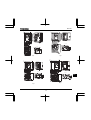
Contents of the product
Explanation of the name plate label.
Type
Form
V F N C 3 S Model name
TOSVERT
VF-nc3series
Number of
power phases
Input (AC) voltage
1 : 100V to 120V
2 : 200V to 240V
2 0 0 7 P L B
Applicable motor
capacity
001 : 0.1kW
002 : 0.2kW
004 : 0.4kW
007 : 0.75kW
015 : 1.5kW
022 : 2.2kW
037 :
4kW
Additional functions I
None: No filter inside
L: Built-in
high-attenuation
EMI filter
None: No filter
P: Provided
S: single-phase
None:
three-phase
Additional function II
Operation panel
None: Standard product
B: Base plate type
Note 1) Always shut power off first then check the ratings label of inverter held in a cabinet.
Note 2) ID label is stuck for special specification product.
A-2
E6581597
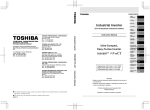
1.3
Names and functions
1.3.1
Outside view
With cover closed
Charge lamp
1
Indicate s there is a high
voltage still in the inverter.
Do not open the terminal
block cover when this lamp
is lit because it is dangerous.
Cover
This is the body or terminal
block cover.
Always close this cover
before operation to avoid
accidentally touching the
terminal block.The serial
number is recorded on the
back side.
Door lock hole
You can lock the door by
shutting it an passing a wire
key through this hole.
[Front view]
Hole for control wire
Upper caution plate (sticker) (Note 1)
RS485 connector
Cooling fin (Note 2)
Hole for main
circuit wiring
Ventilation
Name plate
[Bottom view]
[Side view]
Note 1) Remove the seal as shown on the next page when installing the inverter side by side with other inverters
where the ambient temperature will rise above 40°C.
Note 2) Some models are wrapped in plastic.
A-3
E6581597
Example of the label
1
[Opening the cover]
l 14
l
d
About the monitor display
The LED on the operation panel uses the following symbols to indicate parameters and operations.
LED display (numbers)
0
1
2
3
0
1
2
3
4
4
5
5
6
6
7
7
8
8
9
9
-
LED display (letters)
Aa
Bb
C
c
a
b
c
w
Dd
d
Ee
e
Ff
f
Gg
g
H
h
h
k
I
i
i
}
Jj
j
Kk
Ll
l
Pp
p
Qq
q
Rr
r
Ss
s
Tt
t
Uu
u
Vv
v
Ww
Xx
Yy
y
Zz
Mm
m
Nn
n
O
o
o
x
A-4
E6581597
Warning
Never touch the internal terminals in the upper right while the front cover is open.
There is a risk of shock because it carries a high voltage.
Prohibited
[With cover open]
1
RUN lamp
PRG lamp
When lit, the inverter is
in parameter setting
mode. When blinking,
the inverter is in AUH or
Gr-U.
% lamp
Lit when a frequency is
not output with the ON
run command. This lamp
blinks when operation
starts.
Dispalyed numbers are
percents.
Hz lamp
Displayed numbers are
in Hertz.
High voltage
caution mark
MON lamp
The internal terminal in
the upper right carries a
high voltage. Never
touch it.
While this is lit, the
inverte r is in monitor
mode.
While blinking , the
inverter is in "Past Trip
History Details Monitor
Display".
STOP key
While the runing lamp is
blinking , pressing this
button slows down and
stops the inverter.
RUN key
Pressing this key while
the run lamp is on starts
operation.
MODE key
Setting dial
Switches between run,
settings, and status
monitor modes.
Turning the dial left and
right changes the
operation frequency,
cycles parameters, and
cycles among menus
within parameters.
Switches between easy
and standard setting
modes.
EASY key
A-5
E6581597
1.3.2
Opening the terminal cover
Caution
1
Mandatory
action
When removing and installing the terminal cover with a screwdriver, be sure not to scratch your hand
as this results in injury.
Pressing too hard on the screwdriver may scratch the inverter.
Always cut the power supply when removing the wiring cover.
After wiring is complete, be sure to replace the terminal cover.
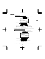
Use the following procedure to remove both the upper and lower terminal block covers.
(1) Removing the lower (output and dc terminals) terminal block cover
1)
2)
Press in on the screwdriver.
Insert a screwdriver or other thin object into the
hole indicated with the
mark.
4)
3)
Pull the terminal cover up at an angle.
While pressing on the screwdriver, rotate the
terminal cover downward to remove it.
A-6
E6581597
(2) Removing the upper terminal (input terminal) block cover
1)
2)
1
Press in on the screwdriver.
Insert a screwdriver or other thin object into the
hole indicated with the
mark.
3)
4)
Pull the terminal cover up at an angle.
While pressing on the screwdriver, rotate the
terminal cover upward to remove it.
★ After wiring is complete, be sure to restore the terminal cover to its original position.
A-7
E6581597
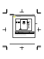
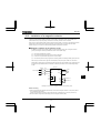
1.3.3
Power circuit and control circuit terminal boards
In case of the lug connector, cover the lug connector with insulated tube, or use the insulated lug connector.
Note 1: EMC plate is supplied as standard.
1) Power circuit terminal board
1
In case of the lug connector, cover the lug connector with insulated tube, or use the insulated lug
connector.
Screw size
Tightening torque
M3.5 screw
1.0Nm
8.9lb in
M4 screw
1.4Nm
12.4lb in
M5 screw
3.0Nm
26.6lb in
Refer to section 2.3.1 for details about terminal functions.
VFNC3-2001 2007P
R/L1
S/L2
T/L3
M3.5 screw
Grounding terminal
Short-circuit cover
M3.5 screw
P0
Grounding terminal
(M4 screw)
PA/+
PC/-
U/T1
V/T2 W/T3
Grounding
terminal
(M5 screw)
Grounding terminal
(M4 screw)
EMC plate
for installation (Note 1)
* Bend the clips on the wiring port of the terminal cover to connect the PO, PA/+, and PC/- terminals.
A-8
E6581597
VFNC3-2015 2037P
R/L1
M4 screw
S/L2
T/L3
Grounding terminal
1
Short-circuit cover
M4 screw
P0
Grounding terminal
M4 screw: 2015, 2202
M5 screw: 2037
PA/+
PC/- U/T1 V/T2 W/T3
Grounding terminal
(M5 screw)
EMC plate
for installation (Note 1)
Grounding terminal
M4 screw: 2015, 2202
M5 screw: 2037
* Bend the clips on the wiring port of the terminal cover to connect the PO, PA/+, and PC/- terminals.
VFNC3S-1001~1004P,2001~2007PL
R/L1 S/L2/N
Grounding terminal
Grounding capacitor switch
(2001 to 2007 PL only)
M3.5 screw
M3.5 screw
Short-circuit cover
P0
PA/+
PC/- U/T1 V/T2 W/T3
Grounding
terminal
(M5 screw)
Grounding terminal
Grounding terminal
(M4 screw)
EMC plate
for installation (Note 1)
* Bend the clips on the wiring port of the terminal cover to connect the PO, PA/+, and PC/- terminals.
A-9
E6581597
VFNC3S-1007P,2015PL,2022PL
R/L1 S/L2/N
Grounding terminal
Grounding capacitor switch
(2015, 2022 PL only)
M4 screw
1
Short-circuit cover
M4 screw
P0
PA/+
PC/- U/T1 V/T2 W/T3
Grounding
terminal
(M5 screw)
EMC plate
for installation (Note 1)
Grounding terminal
(M4 screw)
Grounding terminal
(M4 screw)
* Bend the clips on the wiring port of the terminal cover to connect the PO, PA/+, and PC/- terminals.
When using a crimping terminal, be sure to cover the fastener with an insulating tube or use an insulated
crimping terminal.
Note 1) The EMC plate is optional.
2) Grounding capacitor switch
Single-phase 240 V models have a built-in high-attenuation noise filter and are grounded via a capacitor.
A switch makes for easy switching to reduce leakage current from the inverter and the load on the
capacitor. However, be careful, as reducing the load means non-conformity with the EMC standard on
the inverter itself. Always do switching with the power off.
Pressing this switches the grounding capacitor's capacity from small
to large. (Default setting)
Pulling this switches the grounding capacitor's capacity from large to
small. This reduces the leakage current.
A-10
E6581597
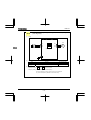
3) Control circuit terminal board
The control circuit terminal board is common to all equipment.
FLA FLB FLC
CC VI
P5 FM
1
RS485 connector
OUT NO CC
Screw size
M2.5 screw
F
R
S1
Recommended
tightening torque
0.5 Nm
4.4 lbin
S2 P24
Stripping length: 6 (mm)
Screwdriver: Small-sized flat-blade screwdriver
Optional connector
(Blade thickness: 0.5 mm, blade width: 3.5 mm)
(RJ45)
Refer to section 2.3.2 for details about all terminal functions.
Wire size
Conductor
Solid
Stranded
1 wire
2 wires of same size
0.3-1.5mm2 (AWG 22-16)
0.3-0.75mm2 (AWG 22-18)
Recommended ferrule
Using ferrule to be improved efficiency and reliability of wiring is recommended.
*2
*2
Wire size
mm2 (AWG)
PHOENIX CONTACT
0.34 (22)
AI 0.34-6TQ
DN00306
0.5 (20)
AI 0.5-6WH
DN00506
0.75 (18)
AI 0.75-6GY
DN00706
1 (18)
AI 1-6RD
DN01006
Type
Dinkle International.,Ltd
1.5 (16)
AI 1.5-8BK
DN01508
2 X 0.5 (-)
AI TWIN2 X 0.5-8WH
DTE00508
AI TWIN2 X 0.75-8GY
DTE00708
2 X0.75 (-)
*1: Crimping pliers
CRIMPFOX ZA3 ( PHOENIX CONTACT )
CT1( Dinkle International.,Ltd )
*2: These ferrules enable practical crimping of two wires in a ferrule.
A-11
E6581597
1.4
Notes on the application
1.4.1
Motors
When the VF-nC3 and the motor are used in conjunction, pay attention to the following items.
Caution
1
Mandatory
action
Use an inverter that conforms to the specifications of power supply and three-phase induction motor
being operated. If the inverter being used does not conform to those specifications, not only will the
three-phase induction motor not rotate correctly, but it may cause serious accidents through overheating
and fire.
Comparisons with commercial power operation
The VF-nC3 Inverter employs the sinusoidal PWM system. However, the output voltage and output
current are not perfect sine waves, they have a distorted wave that is close to sinusoidal waveform.
This is why compared to operation with a commercial power there will be a slight increase in motor
temperature, noise and vibration.
Operation in the low-speed area
When running continuously at low speed in conjunction with a general purpose motor, there may be a
decline in that motor's cooling effect. If this happens, operate with the output decreased from rated load.
To carry out low-speed operation continuously at the rated torque, we recommend to use a inverter
rated motor or a forced cooled motor designed for use with an inverter. When operating in conjunction
with a inverter rated motor, you must change the inverter's motor overload protection level to VF
motor use.
Adjusting the overload protection level
The VF-nC3 Inverter protects against overloads with its overload detection circuits (electronic thermal).
The electronic thermal's reference current is set to the inverter's rated current, so it must be adjusted in
line with the rated current of the motor being used in combination.
High speed operation at and above 60Hz
Operating at frequencies greater than 60Hz will increase noise and vibration. There is also a possibility
this will exceed the motor's mechanical strength limits and the bearing limits so you should inquire to
the motor's manufacturer about such operation.
Method of lubricating load mechanisms
Operating an oil-lubricated reduction gear and gear motor in the low-speed areas will worsen the
lubricating effect. Check with the manufacturer of the reduction gear to find out about operable gearing
area.
A-12
E6581597
Low loads and low inertia loads
The motor may demonstrate instability such as abnormal vibrations or overcurrent trips at light loads of
50% or under of the load percentage, or when the load's inertia moment is extremely small. If that
happens reduce the carrier frequency.
Occurrence of instability
Unstable phenomena may occur with the load and motor combinations shown below.
Combined with a motor that exceeds applicable motor ratings for the inverter
Combine with a much smaller motor according to the applicable motor rating of the inverter.
Combined with special motors
To deal with the above lower the settings of inverter carrier frequency.
Combined with couplings between load devices and motors with high backlash
When using the inverter in the above combination, use the S-pattern acceleration/deceleration function,
or when vector control is selected, adjust the speed control response or switch to V/f control mode.
Combined with loads that have sharp fluctuations in rotation such as piston movements
In this case, adjust the response time (inertial moment setting) during vector control or switch to V/f
control.
Braking a motor when cutting off power supply
A motor with its power cut off goes into free-run, and does not stop immediately. To stop the motor
quickly as soon as the power is cut off install an auxiliary brake. There are different kinds of brake
devices, both electrical and mechanical. Select the brake that is best for the system.
Load that produces regenerative torque
When combined with a load that produces regenerative torque, the overvoltage or overcurrent
protection function may be activated to trip the inverter.
A-13
1
E6581597
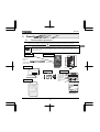
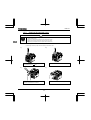
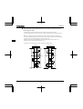
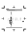
Motors with a brake
When motors with a brake are directly connected to the inverter's output, the brake cannot be released
at startup because of low voltage. Wire the brake circuit separately from the main circuit.
MC2
MC2
B
1
B
MC1
MC1
IM
3-phase
power
source
FLB FLC S2 (ST)
CC
IM
3-phase
power
source
MC3
NO CC P24
OUT
+
–
RY
MC1
RY
MC3
MC2
MC3
MC2
Circuit diagram 1
Circuit diagram 2
In circuit diagram 1, the brake is turned on and off through MC2 and MC3. If you do not wire it as shown
in diagram 1, an over-current trip may occur because of a bound current during brake operation.
(Example of running preparation ST assigned to terminal S2.)
In circuit diagram 2, the brake is turned on and off by using low-speed signal OUT.
In some situations, such as with elevators, turning the brake on and off with a low-speed signal may be
appropriate. Be sure to contact us before designing your system.
1.4.2
Inverters
Protecting inverters from overcurrent
The inverter has an overcurrent protection function. The programmed current level is set to the
inverter's maximum applicable motor. If the motor used has a small capacity, the overcurrent level and
the electronic thermal protection must be readjusted. If adjustment is necessary, refer to section 3.5,
and make adjustments as directed.
Inverter capacity
Do not use a small-capacity (kVA) inverter to control the operation of a large-capacity motor (two-class
or more larger motor), no matter how light the load is. Current ripple will raise the output peak current
making it easier to set off the overcurrent trip.
A-14
E6581597
Power factor correction capacitor
Power factor correction capacitors cannot be installed on the output side of the inverter. When a motor
is run that has a power factor correction capacitor attached to it, remove the capacitors. This can cause
inverter malfunction and capacitor destruction.
U/T1
Inverter
1
IM
V/T2
W/T3
Remove the power factor correction
capacitor and surge absorber
Power factor correction capacitor
Operating at other than rated voltage
Connections to voltages other than the rated voltage described in the rating label cannot be made. If a
connection must be made to a power supply other than one with rated voltage, use a transformer to
raise or lower the voltage to the rated voltage.
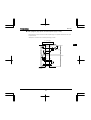
Circuit breaking when two or more inverters are used on the same power line
MCCB1
MCCB2 (circuit breaking fuse)
INV1
MCCB3
MCCBn1
INV2
MCCB:
Molded-case
circuit breaker
INVn
Breaking of selected inverter
There is no fuse in the inverter's main circuit. Thus, as the diagram above shows, when more than one
inverter is used on the same power line, you must select interrupting characteristics so that only
MCCB2 to MCCBn+1 will trip and the MCCB1 will not trip when a short occurs in the inverter (INV1).
When you cannot select the proper characteristics install a circuit interrupting fuse behind MCCB2 to
MCCBn+1.
If power supply distortion is not negligible
If the power supply distortion is not negligible because the inverter shares a power distribution line with
other systems causing distorted waves, such as systems with thyristors or large-capacity inverters,
install an input reactor to improve the input power factor, to reduce higher harmonics, or to suppress
external surges.
A-15
E6581597
Disposal
Refer to chapter 16.
1.4.3
What to do about the leakage current
Caution
1
Mandatory
action
Current may leak through the inverter's input/output wires because of insufficient electrostatic capacity on
the motor with bad effects on peripheral equipment.
The leakage current’s value is affected by the carrier frequency and the length of the input/output wires.
Test and adopt the following remedies against leak current.
(1) Leakage current from the inverter main unit
Some of these inverters are equipped with a ground capacitor compliant with the EMC directive which
gives them a comparatively higher value than a normal inverter. Take this into consideration when
selecting a leakage breaker.
Refer to "Leakage current" (E6581181) in the separate user manual for details.
(2) Influence of leakage current across ground
Leakage current may flow not just through the inverter system but also through ground wires to other
systems. Leakage current will cause earth leakage breakers, leakage current relays, ground relays, fire
alarms and sensors to operate improperly, and it will cause superimposed noise on the TV screen or
display of incorrect current detection with the CT.
Power
supply
ELCB
Inverter
ELCB
Inverter
Leakage current path across ground
A-16
IM
IM
E6581597
Remedies:
1.If there is no radio-frequency interference or similar problem, detach the built-in noise filter
capacitor, using the grounding capacitor disconnecting switch. (Refer to section 1.3.3-2))
2.Reduce PWM carrier frequency.
The setting of PWM carrier frequency is done with the parameter .
Although the electromagnetic noise level is reduced, the motor acoustic noise is increased.
3. Use high frequency remedial products for earth leakage breakers
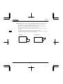
(3) Influence of leakage current across lines
Thermal relays
CT
Inverter
Power
supply
IM
A
Leakage current path across wires
(1)
Thermal relays
The high frequency component of current leaking into electrostatic capacity between inverter output wires will increase the effective current values and make externally connected thermal relays
operate improperly. If the wires are more than 50 meters long, it will be easy for the external
thermal relay to operate improperly with models having motors of low rated current (several
A(ampere) or less), because the leakage current will increase in proportion to the motor rating.
Remedies:
1.Use the electronic thermal built into the inverter. (Refer to section 3.5)
The setting of the electronic thermal is done using parameter , .
2.Reduce the inverter's PWM carrier frequency. However, that will increase the motor's magnetic
noise.
The setting of PWM carrier frequency is done with the parameter . (Refer to section 6.11 in
E6581595)
3.This can be improved by installing 0.1μ~0.5μF - 1000V film capacitor to the input/output terminals of
each phase in the thermal relay.
U/T1
IM
V/T2
W/T3
Thermal relays
A-17
1
E6581597
(2)
1
CT and ammeter
If a CT and ammeter are connected externally to detect inverter output current, the leak current's high
frequency component may destroy the ammeter. If the wires are more than 50 meters long, it will be
easy for the high frequency component to pass through the externally connected CT and be
superimposed on and burn the ammeter with models having motors of low rated current (several A
(ampere) or less), because the leakage current will increase in proportion to the motor's rated current.
Remedies:
1.Use a meter output terminal in the inverter control circuit.
The load current can be output on the meter output terminal (FM). If the meter is connected, use an
ammeter of 1mAdc full scale or a voltmeter of 10V full scale.
0-20mAdc (4-20mAdc) can be also output. (Refer to section 5.6 in E6581595)
2.Use the monitor functions built into the inverter.
Use the monitor functions on the panel built into the inverter to check current values. (Refer to
section 8.2.1)
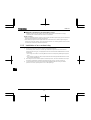
1.4.4
Installation
Installation environment
The VF-nC3 Inverter is an electronic control instrument. Take full consideration to installing it in the proper
operating environment.
Warning
Prohibited
Do not place any inflammable substances near the VF-nC3 Inverter.
If an accident occurs in which flame is emitted, this could lead to fire.
Do not install in any location where the inverter could come into contact with water or other fluids.
This can result in electric shock or fire.
Operate under the environmental conditions prescribed in the instruction manual.
Operations under any other conditions may result in malfunction.
Mandatory
action
Caution
Do not install the VF-nC3 Inverter in any location subject to large amounts of vibration.
This could cause the unit to fall, resulting in bodily injury.
Prohibited
Mandatory
action
Check to make sure that the input power voltage is +10%, -15% of the rated power voltage written on
the rating label (10% when the load is 100% in continuous operation) If the input power voltage is not
+10%, -15% of the rated power voltage (10% when the load is 100% in continuous operation) this
may result in fire.
A-18
E6581597
Do not install in any location of high temperature, high humidity,
moisture condensation and freezing and avoid locations where
there is exposure to water and/or where there may be large
amounts of dust, metallic fragments and oil mist.
Do not install in any location where corrosive gases or grinding
fluids are present.
Operate in areas where ambient temperature ranges from -10°C to 60°C.
Operation over 40°C is allowed when the top label is peeled off. When installing the inverter where the
ambient temperature will rise above 50°C, remove the label (seal) from the top and operate it at a
current lower than the rated one. (Refer to section 6.11 in E6581595)
[Position for measuring ambient temperature]
5cm
5cm
Measurement position
5cm
Measurement position
Note:
The inverter is a heat-emitting body. Make sure proper space and ventilation is provided when
installing in the cabinet. When installing inside a cabinet, we recommend the top seal peeled off
although 40°C or less.
Do not install in any location that is subject to large amounts of vibration.
Note:
If the VF-nC3 Inverter is installed in a location that is subject
to vibration, anti-vibration measures are required. Please
consult with Toshiba about these measures.
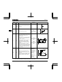
If the VF-nC3 Inverter is installed near any of the equipment listed below, provide measures to insure
against errors in operation.
Solenoids:
Brakes:
Magnetic contactors:
Fluorescent lights:
Resistors:
Resistors
A-19
Attach surge suppressor on coil.
Attach surge suppressor on coil.
Attach surge suppressor on coil.
Attach surge suppressor on coil.
Place far away from VF-nC3 Inverter.
1
E6581597
How to install
Warning
1
Prohibited
Mandatory
action
Do not install or operate the inverter if it is damaged or any component is missing.
This can result in electric shock or fire. Please consult your local sales agency for repairs. Call your
local sales agency for repairs.
Mount the inverter on a metal plate.
The rear panel gets very hot. Do not install in an inflammable object, this can result in fire.
Do not operate with the front panel cover removed.
This can result in electric shock.
An emergency stop device must be installed that fits with system specifications (e.g. shut off input
power then engage mechanical brake).
Operation cannot be stopped immediately by the inverter alone, thus risking an accident or injury.
All options used must be those specified by Toshiba.
The use of any other option may result in an accident.
Caution
Mandatory
action
The main unit must be installed on a base that can bear the unit's weight.
If the unit is installed on a base that cannot withstand that weight, the unit may fall resulting in injury.
If braking is necessary (to hold motor shaft), install a mechanical brake.
The brake on the inverter will not function as a mechanical hold, and if used for that purpose, injury
may result.
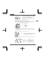
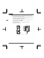
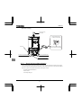
(1) Normal installation
Select an indoor location with good ventilation, and then install it upright on a flat metal plate.
When installing multiple inverters, leave at least 5 cm of space between each inverter and install them
aligned horizontally.
When using the inverter in locations with temperatures above 40°C, remove the caution plate (sticker) on top
of the inverter before use. Current reduction is necessary in locations that exceed 50°C.
(2) Side-by-side installation
To align the inverters side-by-side horizontally, remove the caution plate (sticker) on top of the inverter before
use. Current reduction is necessary in locations that exceed 40 °C.
If the door is opened 90° or more, please open the door with the left side inverter’s door open when the same
capacity inverters are installed with side-by-side.
Normal installation
Side-by-side installation
5 cm or more
5 cm or more
Remove seals on top
3 cm or more
VFnC3
VFnC3
3 cm or more
VFnC3
VFnC3
5 cm or more
5 cm or more
A-20
E6581597
The space shown in the diagram is the minimum allowable space. Because air cooled equipment has cooling
fans built in on the top or bottom surfaces, make the space on top and bottom as large as possible to allow
for air passage.
Note: Do not install in any location where there is high humidity or high temperatures and where there are
large amounts of dust, metallic fragments and oil mist.
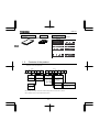
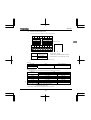
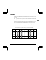
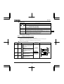
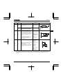
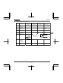
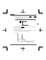
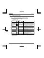
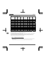
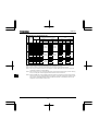
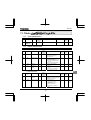
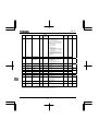
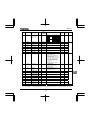
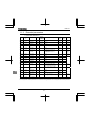
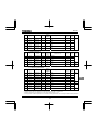
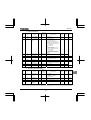
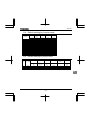
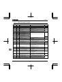
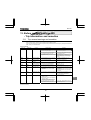
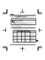
Calorific values of the inverter and the required ventilation
About 5% of the rated power of the inverter will be lost as a result of conversion from AC to DC or from DC to
AC. In order to suppress the rise in temperature inside the cabinet when this loss becomes heat loss, the
interior of the cabinet must be ventilated and cooled.
The amount of forcible air-cooling ventilation required and the necessary heat discharge surface quantity
when operating in a sealed cabinet according to capacity are as follows.
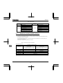
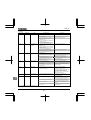
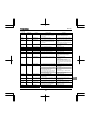
Notes
1)
Case of 100% Load Continuation operation. The heat loss for the optional external devices (input
reactor, DC reactor, radio noise reduction filters, etc.) is not included in the calorific values.
2)
It is power consumption when power is on but output frequency is 0Hz, and cooling fan is activated.
Voltage class
Inverter type
Three-phase
240V class
VFNC3-
Single-phase
240V class
VFNC3S-
Single-phase
120V class
VFNC3S-
2001P
2002P
2004P
2007P
2015P
2022P
2037P
2001PL
2002PL
2004PL
2007PL
2015PL
2022PL
1001P
1002P
1004P
1007P
Calorific values
Note 1)
4kHz
13
16
24
41
73
85
128
13
18
27
44
72
93
13
18
29
48
12kHz
14
18
28
45
85
90
133
14
20
31
43
83
102
14
20
33
54
A-21
Amount of forcible air
cooling ventilation
3
required (m /min)
4kHz
12kHz
0.07
0.08
0.09
0.10
0.14
0.16
0.23
0.26
0.41
0.48
0.48
0.51
0.73
0.75
0.07
0.08
0.10
0.11
0.15
0.18
0.24
0.25
0.47
0.41
0.53
0.53
0.07
0.08
0.10
0.11
0.16
0.19
0.27
0.31
Heat discharge surface
area required for sealed
3
storage cabinet (m )
4kHz
12kHz
0.26
0.28
0.32
0.36
0.48
0.56
0.82
0.90
1.46
1.70
1.70
1.80
2.56
2.66
0.26
0.28
0.36
0.40
0.54
0.62
0.88
0.86
1.44
1.66
1.86
2.04
0.26
0.28
0.36
0.40
0.58
0.66
0.96
1.08
Standby power
requirement
(W)
Note 2)
8
8
8
8
12
12
12
8
8
8
8
11
11
8
8
8
11
1
E6581597
Panel designing taking into consideration the effects of noise
1
The inverter generates high frequency noise. When designing the control panel setup, consideration must be
given to that noise. Examples of measures are given below.
Wire so that the main circuit wires and the control circuit wires are separated. Do not place them in the
same conduit, do not run them parallel, and do not bundle them.
Provide shielding and twisted wire for control circuit wiring.
Separate the input (power) and output (motor) wires of the main circuit. Do not place them in the same
conduit, do not run them parallel, and do not bundle them.
Ground the inverter grounding terminals ( ).
Install surge suppressor on any magnetic contactor and relay coils used around the inverter.
Install noise filters if necessary.
To comply with the EMC directives, install the optional EMC plate and fix the shield to it.
Install EMC plate and use shielded wires.
EMC Plate
A-22
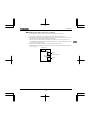
E6581597
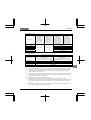
Installing more than one unit in a cabinet
If you are installing two or more inverters in one cabinet, pay attention to the following.
Inverters may be installed side by side with each other with no space left between them.
When installing inverters side by side, detach the caution label on the top surface of each inverter and
use them where the ambient temperature will not rise above 40°C.
When using inverters where the ambient temperature will rise above 40°C, leave a space of 3 cm or
more between them and remove the caution label from the top of each inverter, or operate each inverter
at a current lower than the rated one.
Ensure a space of at least 20 centimeters on the top and bottom of the inverters.
Install an air deflecting plate so that the heat rising up from the inverter on the bottom does not affect the
inverter on the top.
Ventilation fan
Inverter
Air deflecting plate
Inverter
A-23
1
E6581597
2. Connection
Warning
Never disassemble, modify or repair.
This can result in electric shock, fire and injury. For repairs, call your sales agency.
Disassembly
prohibited
Prohibited
Don't stick your fingers into openings such as cable wiring hole and cooling fan covers.
This can result in electric shock or other injury.
Don't place or insert any kind of object into the inverter (electrical wire cuttings, rods, wires). This can
result in electric shock or fire.
Do not allow water or any other fluid to come in contact with the inverter.
That may result in electric shock or fire.
Caution
When transporting or carrying, do not hold by the front panel covers.
The covers may come off and the unit will drop out resulting in injury.
Prohibited
2.1
Cautions on wiring
Warning
Never remove the terminal cover when power is on or open door if enclosed in a cabinet.
The unit contains many high voltage parts and contact with them will result in electric shock.
Prohibited
Mandatory
action
Turn power on only after attaching the front cover or closing door if enclosed in a cabinet.
If power is turned on without the terminal cover attached or closing door if enclosed in a cabinet. This
can result in electric shock or other injury.
Electrical construction work must be done by a qualified expert.
Connection of input power by someone who does not have that expert knowledge may result in fire or
electric shock.
Connect output terminals (motor side) correctly.
If the phase sequence is incorrect, the motor will operate in reverse and that may result in injury.
Wiring must be done after installation.
If wiring is done prior to installation that may result in injury or electric shock.
The following steps must be performed before wiring.
(1) Shut off all input power.
(2) Wait at least 15 minutes and check to make sure that the charge lamp is no longer lit.
(3) Use a tester that can measure DC voltage (400VDC or more), and check to make sure that the
voltage to the DC main circuits (across PA-PC) is 45V or less.
If these steps are not properly performed, the wiring will cause electric shock.
Tighten the screws on the terminal board to specified torque.
If the screws are not tightened to the specified torque, it may lead to fire.
B-1
2
E6581597
Warning
Be Grounded
Ground must be connected securely.
If the ground is not securely connected, it could lead to electric shock or fire when a malfunction or
current leak occurs.
Caution
2
Prohibited
Do not attach devices with built-in capacitors (such as noise filters or surge absorber) to the output
(motor side) terminal.
This could cause a fire.
■ Preventing radio noise
To prevent electrical interference such as radio noise, separately bundle wires to the main circuit's power
terminals (3-phase models: R/L1, S/L2, T/L3, single-phase models: R/L1, S/L2/N) and wires to the motor
terminals (U/T1, V/T2, W/T3).
■ Control and main power supply
The control power supply and the main circuit power supply for the VFnC3 are the same.
If a malfunction or trip causes the main circuit to be shut off, control power will also be shut off. When
checking the cause of the malfunction or the trip, use the trip holding retention selection parameter.
■ Wiring
Because the space between the main circuit terminals is small use sleeved pressure terminals for the
connections. Connect the terminals so that adjacent terminals do not touch each other.
For ground terminal
use wires of the size that is equivalent to or larger than those given in table 10.1
and always ground the inverter (240V voltage class: D type ground).
Use as large and short a ground wire as possible and wire it as close as possible to the inverter.
For the sizes of electric wires used in the main circuit, refer to the table in section 10.1.
The length of the main circuit wire in table 10.1 should be no longer than 30 meters. If the wire is longer
than 30 meters, the wire size (diameter) must be increased.
B-2
E6581597
2.2
Standard connections
Warning
Prohibited
Do not connect input power to the output (motor side) terminals (U/T1, V/T2, W/T3).
Connecting input power to the output could destroy the inverter or cause a fire.
Do not insert a resistor between DC terminals (between PA/+ and PC/-, or between PO and PC/-).
It could cause a fire.
See 6.13.4 for the connection of a resistor.
First shut off input power and wait at least 15 minutes before touching wires on equipment (MCCB) that
is connected to inverter power side.
Touching the wires before that time could result in electric shock.
Set a parameter f109 when VI terminal is used as logic input terminal.
If it is not set, it could result in malfunction.
Mandatory
action
Be Grounded
Ground must be connected securely.
If the ground is not securely connected, it could lead to electric shock or fire when a malfunction or
current leak occurs.
B-3
2
E6581597
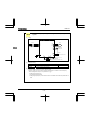
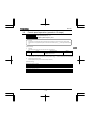
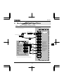
2.2.1
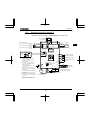
Standard connection diagram 1
This diagram shows a standard wiring of the main circuit.
Standard connection diagram - SINK (Negative) (common:CC)
DC reactor (DCL)
*2 , *5 (option)
2
PA/+
P0
Main circuit power supply
MCCB
3ph-240V class: three-phase 200-240V
-50/60Hz
1ph-240V class: single-phase 200-240V
-50/60Hz
1ph-120V class: single-phase 100-120V
-50/60Hz
R/L1
S/L2
T/L3
Noise
filter
MCCB(2P)
R/L1
*1
S/L2/N
Protective function
activation output
VF-nC3
FLB
FLC
Operation panel
Use the R/L1 and S/L2 terminal as
input terminals.
*2: The inverter is supplied with the PO
and the PA/+ terminals shorted by
means of a shorting bar.
*4: 1ph-240V models have noise filter inside.
*5: 1ph-120V models cannot be used with
DC reactors.
*6: When external potentiometer is connected
by using P5 terminal, set the parameter
f109=3.
FM
Meter
IM
CC
+
VI
F
Forward run command
R
Reverse run command
S1
Preset-speed command 1
S2
Preset-speed command 2
CC
Common
P24
OUT
RS485
communication
connector
*7
Before installing the DC reactor (DCL),
remove the bar.
Motor
Control
circuit
*1: The T/L3 terminal is not provided
for single-phase models.
*3: When using the OUT output terminal in
sink logic mode, short the NO and CC
terminals.
U/T1
V/T2
W/T3
Power
circuit
*4
FLA
Single phase
Power supply
PC/-
Ry
NO
P5
Low-speed
signal output
*3
CC
+
Voltage signal: 0-5V/0-10V
- (Current signal: 4-20mA)
Frequency
meter
(ammeter)
7.5V-1mA
(or 0-10V/4-20mA)
*7: When VI terminal is used as a logic
input terminal, refer to page B-10.
B-4
External potentiometer (1k-10k) *6
E6581597
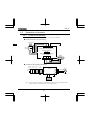
2.2.2
Standard connection diagram 2
Standard connection diagram - SOURCE (Positive) (common:P24)
DC reactor (DCL)
*2 , *5 (option)
PA/+
P0
Main circuit power supply
MCCB
3ph-240V class: three-phase 200-240V
-50/60Hz
1ph-240V class: single-phase 200-240V
-50/60Hz
1ph-120V class: single-phase 100-120V
-50/60Hz
R/L1
S/L2
T/L3
Noise
filter
*4
*1
MCCB(2P)
R/L1
S/L2/N
Protective function
activation output
Motor
U/T1
V/T2
W/T3
Power
circuit
IM
VF-nC3
FLB
FLC
F
Forward run command
R
Reverse run command
S1
*1: The T/L3 terminal is not provided
for single-phase models.
Operation panel
Use the R/L1 and S/L2 terminal as
input terminals.
*4: 1ph-240V models have noise filter inside.
*5: 1ph-120V models cannot be used with
DC reactors.
*6: When external potentiometer is connected
by using P5 terminal, set the parameter
f109=3.
Meter
CC
NO
-
P5
Ry
CC
+
+
Low-Speed
signal output
Voltage signal: 0-5V/0-10V
- (Current signal: 4-20mA)
Frequency
meter
(ammeter)
7.5V-1mA
(or 0-10V/4-20mA)
VI
*3
OUT
*7
FM
Preset-speed command 2
Common
P24
RS485
communication
connector
*2: The inverter in supplied with the PO
and the PA/+ terminals shorted by
means of a shorting bar.
*3: When using the NO output terminal in
source logic mode, short the P24 and
OUT terminals.
Preset-speed command 1
S2
Before installing the DC reactor (DCL),
remove the bar.
2
Control
circuit
FLA
Single phase
Power supply
PC/-
External potentiometer (1k-10k) *6
*7: When VI terminal is used as a contact
input terminal, refer to page B-10.
B-5
E6581597
2.3
Description of terminals
2.3.1
Power circuit terminals
This diagram shows an example of wiring of the main circuit. Use options if necessary.
■ Power supply and motor connections
Power supply
2
R/L1 S/L2 T/L3
No-fuse
breaker
Power lines are connected +0
R/L1,S/L2 and T/L3.
VF-nC3
Motor lines are connected to
U/T1,V/T2 and W/T3.
Motor
U/T1 V/T2 W/T3
E
■ Connections with peripheral equipment
Molded-case Magnetic
circuit braker contactor
Input AC
reactor
Noise
reduction filter
R/L1
Power
supply
Inverter
V/T2
T/L3
W/T3
PA/+ PO
Motor
U/T1
S/L2
IM
Zero-phase
reactor
DC reactor
Note 1: The T/L3 terminal is not provided for any single-phase models. So if you are using single-phase
models, use the R/L1 and S/L2/N terminals to connect power cables.
B-6
E6581597
■ Power circuit
Terminal symbol
R/L1,S/L2,T/L3
U/T1,V/T2,W/T3
PC/PO, PA/+
Terminal function
Grounding terminal for connecting inverter.
There are 4 terminals in total. (1 terminal on upper side, 3 terminals on down side)
240V class: three-phase 200 to 240V-50/60Hz
single-phase 200 to 240V-50/60Hz
120V class: single-phase 100 to 120V-50/60Hz
* Single-phase input: R/L1 and S/L2/N terminals
Connect to a (three-phase induction) motor.
This is a negative potential terminal in the internal DC main circuit. DC common power
can be input across the PA terminals (positive potential).
DC common power can not connect to 1-phase 120V models.
Terminals for connecting a DC reactor (DCL: optional external device). Shorted by a
short bar when shipped from the factory. Before installing DCL, remove the short bar.
1-phase 120V models cannot be used with DC reactors.
The arrangements of power circuit terminals are different from each range.
Refer to section 1.3.3.1) for details.
2.3.2
Control circuit terminals
The control circuit terminal board is common to all equipment.
Regarding to the function and specification of each terminal, please refer to the following table.
Refer to section 1.3.3.3) about the arrangement of control circuit terminals.
■ Control circuit terminals
F
R
S1
S2
Input /
output
Input
Input
Input
Input
Electrical
specifications
Function
Multifunction programmable logic input
Terminal
symbol
Shorting across F-CC causes
forward rotation; open causes slowdown and stop. (When Standby ST
is always ON)
3 different functions can be
assigned.
Shorting across R-CC causes
reverse rotation; open causes slowdown and stop. (When Standby ST
is always ON)
3 different functions can be
assigned.
Shorting across S1-CC causes
preset speed operation.
2 different functions can be
assigned.
Shorting across S2-CC causes
preset speed operation.
2 different functions can be
assigned.
B-7
No voltage
logic input
24Vdc-5mA or less
*Sink/Source
selectable using
parameter
(In case of sink
logic is the left)
Inverter internal circuits
+24V
OFF:
External
24V
ON:
Sink
P24
2.2k
F
R
S1
S2
CC
470
2.2k
OFF:
Source
2
E6581597
Terminal
symbol
2
Input /
output
Electrical
specifications
Function
CC
Common
to Input /
output
Control circuit's equipotential terminal (2
terminals)
P5
Output
Analog power supply output
Inverter internal circuits
CC
+5V
100
5Vdc
(permissible load
current: 10mA)
P5
CC
Multifunction programmable analog input.
Factory default setting: 0-10Vdc (1/1000
resolution) and 0-60Hz (0-50Hz)
frequency input.
The function can be changed to 0-20mAdc
(4-20mA) current input by parameter
5V/10Vdc
=1 setting.
(internal impedance:
40k)
0-5Vdc (1/1000 resolution) voltage input
VI
Input
by parameter =3 setting.
Switch to this setting when external
potentiometer is connected by using P5
terminal.
By changing parameter f109=2
setting, this terminal can also be used as
a multifunction programmable logic input
terminal. When using the sink logic, be
sure to insert a resistor between P24-VI
(4.7 k-1/2 W).
+5V
1.6k
250
FM
Output
47k
39.2k
4-20mA
(internal
impedance: 250)
Note 1)
0-20mA (4-20mA)
DC ammeter
Permissible load
resistance:
750Ω or less
0-10V DC volt
meter
Permissible load
resistance:
1kΩ or more
ON:10V
OFF:5V
CC
ON:Current
OFF:Voltage
1mAdc full-scale
ammeter or
QS60T(option)
Multifunction programmable analog
output. Standard default setting: output
frequency.
The function can be changed to 0-10Vdc
voltage or 0-20mAdc (4-20mA) current
output by parameter setting.
47k
VI
121
2.7k
+
–
ON:Meter
FM
ON:Voltage +24V
Meter
ON:Current
CC
68
+
–
Note 1) Be careful, if 4-20mA is selected, when the inverter's power is ON, the internal impedance is 250Ω, but when the power
is OFF, the internal impedance increases very much to approximately 40kΩ.
B-8
E6581597
Terminal
symbol
Input /
output
Output
Electrical
specifications
Function
24Vdc power output
Inverter internal circuits
24Vdc-100mA
Over current
protection circuit
P24
P24
Input
OUT
NO
FLA
FLB
FLC
Note 2)
Output
Output
This terminal can be used as an external
24Vdc input for logic input terminal by
changing parameter f127=200.
CC
OFF:f127=200
-
Multifunction programmable open
collector output. Standard default setting
detect and output low speed signal.
Multifunction output terminals to which
two different functions can be assigned.
The NO terminal is an isoelectric output
terminal. It is insulated from the CC
terminal.
Open collector output
24Vdc-100mA
By changing parameter settings, these
terminals can also be used as
multifunction programmable pulse train
output terminals.
Pulse frequency
range:
38~1600pps
Multifunction programmable relay contact
output.
Detects the operation of the inverter's
protection function.
Contact across FLA-FLC is closed and FLBFLC is opened during protection function
operation.
+24V
To output pulse
trains,
a current of 10mA
or more needs to
be passed.
Max. switching
capacity
250Vac-2A
30Vdc-2A
(cos=1)
: at resistive load
250Vac-1A
(cos=0.4)
30Vdc-1A
(L/R=7ms)
2
OUT
10
NO
FLA
+24V
FLB
RY
FLC
Min. permissible
load
5Vdc-100mA
24Vdc-5mA
Note 2) A chattering (momentary ON/OFF of contact) is generated by external factors of the vibration and the impact, etc. In
particular, please set the filter of 10ms or more, or timer for measures when connecting it directly with input unit terminal
of programmable controller. Please use the OUT terminal as much as possible when the programmable controller is
connected.
B-9
E6581597
■ SINK (Negative) logic/SOURCE (Positive) logic (When the inverter's internal
power supply is used)
2
Current flowing out turns control input terminals on. These are called sink logic terminals.
The general used method in Europe is source logic in which current flowing into the input terminal turns it
on.
Sink logic is sometimes referred to as negative logic, and source logic is referred to as positive logic.
Each logic is supplied with electricity from either the inverter's internal power supply or an external power
supply, and its connections vary depending on the power supply used.
Setting of sink/source logic varies depending on the setup menu setting. (Refer to section 11.5)
Sink/source logic can be switched by parameter .
<Examples of connections when the inverter's internal power supply is used>
f127=0
f127=100
Sink (Negative) logic
Source (Positive) logic
24VDC
Output
24VDC
Input
Common P24
Input
F
Output
F
Common CC
24VD
Programmable
controller
24VDC
Output
Common P24
P24
Input
OUT
OUT
NO
Input
CC
Common CC
Inverter
B-10
Programmable
controller
NO
Inverter
Output
E6581597
■ SINK (Negative) logic (When an external power supply is used)
The P24 terminal is used to connect to an external power supply or to separate a terminal from other input
or output terminals.
<Examples of connections when an external power supply is used>
f127=200
Sink (Negative) logic
24VDC
24VDC
Common
P24
Output
F
2
Input
OFF
(f127=200)
CC
24VDC
Output
Input
OUT
Common NO
Programmable
controller
Inverter
B-11
E6581597
■ Selecting the functions of the VI terminal between analog input and logic input
2
The functions of the VI terminal can be selected between analog input and logic input by changing
parameter settings (). (Factory default setting: Analog input 0-10V)
Be sure to connect a resistor between P24 and VI terminals in case of sink logic, between VI and CC
terminals in case of source logic. (Recommended resistance: 4.7k-1/2W)
When using VI terminal as a logic input terminal, set the parameter = and connect as following
schematics.
If no resistor is inserted, logic input will be left always ON, which is very dangerous.
Switch between analog input and logic input before connecting the terminals to the control circuit terminals.
Otherwise the inverter or devices connected to it may be damaged.
<Sink logic>
<Source logic>
P24
P24
4.7kΩ
VI
VI
CC
CC
4.7kΩ
B-12
E6581597
3. Operations
Caution
Prohibited
Mandatory
action
Do not touch inverter terminals when electrical power is going to the inverter even if the motor is
stopped.
Touching the inverter terminals while power is connected to it may result in electric shock.
Do not touch switches when the hands are wet and do not try to clean the inverter with a damp cloth.
Such practices may result in electric shock.
Do not go near the motor in alarm-stop status when the retry function is selected.
The motor may suddenly restart and that could result in injury.
Take measures for safety, e.g. attaching a cover to the motor, against accidents when the motor
unexpectedly restarts.
If the inverter begins to emit smoke or an unusual odor, or unusual sounds, immediately turn power off.
If the equipment is continued in operation in such a state, the result may be fire. Call your local sales
agency for repairs.
Always turn power off if the inverter is not used for long periods of time.
Turn the input power on only after attaching the terminal block cover.
When enclosed inside a cabinet and used with the terminal block cover removed, always close the
cabinet doors first and then turn the power on. If the power is turned on with the terminal block cover or
the cabinet doors open, this may result in electric shock.
Make sure that operation signals are off before resetting the inverter after malfunction.
If the inverter is reset before turning off the operating signal, the motor may restart suddenly causing
injury.
Caution
Do not touch heat radiating fins or discharge resistors.
These devices are hot, and you'll get burned if you touch them.
Contact
prohibited
Prohibited
Observe all permissible operating ranges of motors and mechanical equipment. (Refer to the motor's
instruction manual.)
Not observing these ranges may result in injury.
C-1
3
E6581597
3.1
How to Set the Setup Menu
Warning
If incorrect setting, the drive may has some damage or unexpected movement. Be sure to set the
setup parameter correctly.
Mandatory
action
Set the setup menu according to the logic for control input signals used and the base frequency of the motor
connected. (If you are not sure which setup menu should be selected region codes and what values should be
3
specified, consult your distributer.)
Each setup menu automatically sets all parameters relating to the logic for control input signals used and the base
frequency of the motor connected. (See the table on the following page.)
Follow these steps to change the setup menu [Example: Selecting a region code to ]
Panel operated
LED display
Operation
eu
asia
Power on. (set is blinking)
jp
usa
Turn the setting dial, and select region code ""
(Europe).
Press the center of the setting dial to determine the
region.
The operation frequency is displayed (Standby).
☆ When changing the region selected in the setup menu, the setup menu can be called again by the following
method. Note, however, that all parameter settings return to standard defaults.
Set parameter to "".
Set parameter to "".
☆ The parameter settings in the table on the following page can be changed individually even after they are
selected in the setup menu.
C-2
E6581597
Values set by each setup parameter
Title
Function
Maximum
frequency
/
/
Frequency
settings
(Mainly in
Europe)
(Mainly in North
America)
(Mainly in Asia,
Oceania)
(Mainly in Japan)
50.0(Hz)
60.0(Hz)
50.0(Hz)
80.0(Hz)
50.0(Hz)
60.0(Hz)
50.0(Hz)
60.0(Hz)
VI input point 2
frequency
50.0(Hz)
60.0(Hz)
50.0(Hz)
60.0(Hz)
/
Base frequency
voltage 1, 2
230(V)
230(V)
230(V)
200(V)
Sink/source
switching
100 [ Source logic ]
(Positive common)
(Common : P24)
0 [ Sink logic ]
(Negative common)
(Common : CC)
P24
F, R, S1, S2
CC
F, R, S1, S2
Supply voltage
correction
(output voltage
limitation)
2
2
2
3
Motor rated
speed
1410(min-1)
1710(min-1)
1410(min-1)
1710(min-1)
C-3
3
E6581597
3.2
Simplified Operation of the VF-nC3
The procedures for setting operation frequency and the methods of operation can be selected from the following.
Run / Stop
Setting the frequency
3
: (1) Run and stop using the panel keypad
(2) Run and stop using external signals to terminal
board
: (1) Setting using setting dial
(2) Setting using external signals to terminal board
(0-5V/0-10Vdc, 4-20mAdc)
Use the basic parameters (command mode selection)
and (frequency setting mode selection) for selection.
[Parameter setting]
Title
Function
Command mode selection
Frequency setting mode
selection
Adjustment range
0: Terminal board
1: Panel keypad (including extension
panel)
2: RS485 communication
0: Terminal board VI
1: Setting dial 1 (press in center to save)
2: Setting dial 2 (save even if power is off)
3: RS485 communication
4: 5: UP/DOWN form external logic input
Default setting
1
2
☆ fmod=2 (setting dial 2) is the mode where after the frequency is set by the setting dial, the frequency is
saved even if the power is turned off.
☆ Refer to section 5.5 in E6581595 for details about = and .
C-4
E6581597
3.2.1
How to run and stop
[Example of a setting procedure]
Panel operation
LED display
MODE
Operation
Displays the operation frequency (operation stopped).
(When standard monitor display selection = [Operation frequency])
Displays the first basic parameter [History ()].
Turn the setting dial, and select "".
Press the center of the setting dial to read the parameter value.
(Standard default: ).
Turn the setting dial to change the parameter value to (terminal block).
Press the center of the setting dial to save the changed parameter.
and the parameter set value are displayed alternately.
(1) Run and stop using the panel keypad (=)
Use the RUN and STOP keys on the panel keypad to start and stop the motor.
RUN : Motor runs.
STOP : Motor stops.
,
The direction of rotation is determined by the setting of parameter (forward run, reverse run
selection). (: forward run, : reverse run)
,
To switch between forward run and reverse run from the extension panel (option), the parameter
(forward run, reverse run selection) needs to be set to or . (Refer to section 5.7 in E6581595)
(2) RUN / STOP by means of an external signal to the terminal board (=):
Sink (Negative) logic
Use external signals to the inverter terminal board to start and stop the motor.
Short
F
and
CC
terminals: run forward
Open
F
and
CC
terminals: slow down and stop
Frequency
C-5
F-CC
Slow down
and stop
ON
OFF
3
E6581597
(3) Coast stop
The standard default is slowdown stop. To make a
coast stop, assign "6 (ST)" to an idle terminal.
Change to =.
For coast stop, open the ST-CC when stopping the
motor in the state described at left.The monitor on the
inverter at this time will display .
A coast stop can also be made by assigning "
(FRR)" to an idle terminal.
When doing this, a coast stop is done by FRR and CC
both turning on.
3.2.2
3
Coast stop
Motor
speed
F-CC
ON
OFF
ST-CC
ON
OFF
How to set the frequency
[Example of setting procedure]: Setting the frequency setting destination to the terminal block
Panel operation
LED display
Operation
MODE
Displays the first basic parameter [History ()].
Turn the setting dial, and select "".
Press the center of the setting dial to read the parameter value.
(Standard default: ).
Turn the setting dial to change the parameter value to (terminal block
VI).
*
Displays the operation frequency (operation stopped).
(When standard monitor display selection = [Operation frequency])
The parameter value is written. and the parameter value are
displayed alternately several times.
Pressing the MODE key twice returns the display to standard monitor mode (displaying operation frequency).
(1) Setting using the keypad (= or )
: Moves the frequency up
: Moves the frequency down
Example of operating from the panel (=: press in center to save)
Panel operation
LED display
Operation
Displays the operation frequency.
(When standard monitor display selection = [Operation frequency])
Set the operation frequency. (The frequency will not be saved if the
power is turned off in this state.)
Save the operation frequency. and the frequency are displayed
alternately.
C-6
E6581597
Example of operating from the panel (=: save even if power is off)
Panel operation
LED display
-
Operation
Display the operation frequency.
(When standard monitor display selection is set as =
[operation frequency])
Set the operation frequency.
The frequency will be saved even if the power is turned off in this
state.
3
C-7
E6581597
(2) Setting of frequency using external signals to terminal block (=)
Frequency setting
1)
Setting the frequency using external potentiometer
★Potentiometer
Setting frequency using the potentiometer (1-10k, 1/4W)
Refer to section 6.5.2 in E6581595 for detailed adjustment.
P5
VI
: Setting frequency
using potentiometer
50 or 60Hz
Frequency
CC
3
0
MIN
Note) Set parameter =.
2)
MAX
Setting the frequency using voltage input (0-10V)
+
VI
-
CC
★Voltage signal
Setting frequency using voltage signals (0-10V).
Refer to section 6.5.2 in E6581595 for detailed adjustment.
: Voltage signal 0-10Vdc
50 or 60Hz
Frequency
Note) Set parameter =.
3)
0
0Vdc
10Vdc
Setting the frequency using current input (4-20mA)
+
VI
-
CC
★Current Signal
Current signal Setting frequency using current signals (4-20mA).
Refer to section 6.5.2 in E6581595 for detailed adjustment.
: Current signal 4-20mAdc
50 or 60Hz
Frequency
* Setting of parameters also allow 0-20mAdc.
Note) Set parameter = and =.
4)
0
4mAdc
20mAdc
Setting the frequency using voltage input (0-5V)
+
VI
-
CC
★Voltage signal
Set the frequency using voltage signals (0-5V).
Refer to section 6.5.2 in E6581595 for detailed adjustment.
: Voltage signal 0-5Vdc
50 or 60Hz
Frequency
Note) Set parameter =.
0
0Vdc
C-8
5Vdc
E6581597
3.3
How to operate the VF-nC3
Overview of how to operate the inverter with simple examples.
Setting the frequency using the setting dial, and run/stop using the
panel keypad (1)
Ex.1
(1)
Wiring
PO
PA/+
PC/-
Motor
R/L1
U/T1
S/L2
V/T2
T/L3
W/T3
IM
Operation panel
(2)
Parameter setting (default setting)
Title
(3)
Operation
Function
Programmed value
Command mode selection
1
Frequency setting mode selection
2
Run/stop: Press the RUN
and STOP
keys on the panel.
Frequency setting: Turn the setting dial to set the frequency. The frequency setting is saved just by
turning the setting dial.
C-9
3
E6581597
Setting the frequency using the setting dial, and run/stop using the
panel keypad (2)
Ex.2
(1)
Wiring
PA/+
PO
PC/-
Motor
3
R/L1
U/T1
S/L2
V/T2
T/L3
W/T3
IM
Operation panel
(2)
Parameter setting
Title
(3)
Function
Command mode selection
Frequency setting mode selection
Operation
Run/stop: Press the RUN and STOP keys on the panel.
Programmed value
1
1
Frequency setting: Turn the setting dial to set the frequency.
To save the frequency setting, press the center of the setting dial.
and the set frequency will flash on and off alternately.
C-10
E6581597
Setting the frequency using the setting dial, and run/stop using
external signals
Ex.3
(1)
Wiring
PO
PA/+
PC/-
Motor
MCCB
U/T1
R/L1
S/L2
T/L3
V/T2
W/T3
Operation panel
F
Forward
signal
R
Reverse
signal
CC
(2)
Common
Parameter setting
Title
(3)
IM
Function
Command mode selection
Frequency setting mode selection
Operation
Run/stop: ON/OFF input to F-CC, R-CC. (with sink logic)
Frequency setting: Turn the setting dial to set the frequency.
C-11
Programmed value
0
1 or 2
3
E6581597
Setting the frequency using external signals, run/stop using external
signals.
Ex.4
(1)
Wiring
PO
PA/+
PC/-
Motor
MCCB
R/L1
3
U/T1
S/L2
V/T2
T/L3
W/T3
IM
F
Forward signal
R
Reverse signal
CC
Common
Current signal: 420mA
VI
CC
VI
PP
Voltage signal: 010V / 05V
External potentiometer
(Otherwise, input voltage signal between the terminals VI-CC.)
(2)
Parameter setting
Title
(3)
Function
Command mode selection
Programmed value
0
Frequency setting mode selection
0
Operation
Run/stop: ON/OFF input to F-CC, R-CC. (with sink logic)
Frequency setting: VI: Input 0-10Vdc (external potentiometer) or 4-20mAdc to set the frequency.
* Set the voltage/current input of VI in parameter .
0: Voltage signal input (0-10V)
1: Current signal input (4-20mA)
3: Voltage signal input (0-5V), when the P5 terminal is connected and the external potentiometer is
used
C-12
E6581597
3.4
Meter setting and adjustment
: Meter selection
: Meter adjustment gain
Function
Output of 0 - 1mAdc, 0 (4) - 20mAdc, 0 - 10vdc can be selected for the output signal from the FM
terminal, depending no the setting. Adjust the scale at .
Use an ammeter with a full-scale 0 - 1mAdc meter.
The (analog output bias) needs to be adjusted if output is 4 - 20mAdc.
3
[Parameter setting]
Title
Function
Meter
selection
Meter
adjustment
gain
Adjustment range
0: Output frequency
1: Output current
2: Frequency reference
3: Input voltage (DC detection)
4: Output voltage (command value)
5 to 11: 12: Frequency setting value (after
campensation)
13: VI input value
14: 15: Fixed output 1 (output current 100%
equivalent)
16: Fixed output 2 (output current 50%
equivalent)
17: Fixed output 3 (other than the
output current)
18: RS485 communication data
19:For adjustments ( set value is
displayed.)
20 to 22: -
Supposition output at
fsl=17
Maximum frequency ()
Maximum frequency (fh)
1.5x rated voltage
1.5x rated voltage
Maximum frequency (fh)
Maximum input value
-
0
Maximum value (100.0%)
-
C-13
Default setting
-
E6581597
Resolution
All FM terminals have a maximum of 1/255.
Example of 4-20mA output adjustment (Refer to section 6.17.2 for details)
=1, =0
=1, =20
(mA)
20
(mA)
20
Output
Output
currrent
currrent
3
f692
0
0
100%
4
0
100%
Internal calculated value
Internal calculated value
Note 1) When using the FM terminal for current output, be sure that the external load resistance is less than 750Ω.
Use at over 1kΩ external load resistance, if used for voltage output.
Note 2) = is the motor drive frequency.
Adjustment scale with parameter (Meter adjustment)
Connect meters as shown below.
<Frequency meter>
FM
<Ammeter>
+
Meter: Frequency meter
(default setting)
FM
VF-nC3
Meter: ammeter
+ (=)
VF-nC3
CC
-
* Optional QS-60T frequency meter
is available.
CC
The reading of the
frequency meter
will fluctuate during
scale adjustment.
The reading of the
ammeter will
fluctuate during
scale adjustment.
* Ammeter with a maximum scale of 1.5x the inverter's
rated output is recommended.
C-14
E6581597
[Example of how to adjustment the FM terminal frequency meter]
*
Use the meter's adjustment screw to pre-adjust zero-point.
Operation panel action LED display
Operation
-
.
Displays the output frequency.
(When standard monitor display selection is set to )
MODE
The first basic parameter “” (history function) is displayed.
.
Turn the setting dial to select .
Operation frequency can be read by pressing the center of the setting
dial.
Turn the setting dial to adjust the meter.
Note that the meter's indicator changes at this time, but the inverter's
display (monitor) does not change.
.
⇔
MODE + MODE
.
Press the center of the setting dial to save the meter's calibrations.
and the frequency are displayed alternately.
The display returns to its original indications.
(When standard monitor display selection is set to
[Operation frequency])
Adjusting the meter in inverter stop state
Adjustment of output current (=1)
If, when adjusting the meter for output current, there are large fluctuations in data during adjustment,
making adjustment difficult, the meter can be adjusted in inverter stop state.
When setting to for fixed output 1 (output current 100% equivalent), a signal of absolute
values will be output (inverter's rated current = 100%). In this state, adjust the meter with the (Meter
adjustment) parameter.
Similarly, if you set to for fixed output 2 (output current 50% equivalent), a signal that is sent
out when half the inverter's rated current is flowing will be output through the FM terminal.
After meter adjustment is ended, set to (output current).
Other adjustments ( = , - , , , )
= : When fixed output 3 (other than the output current) is set, a signal of the the value for
other monitors is fixed at the following values and output through the FM terminal.
100% standard value for each item is the following:
=0, 2, 12 : Maximum frequency (h)
=3, 4
: 1.5 times of rated voltage
=13
: Maximum input value (5V, 10V, or 20mA)
=18
: Maximum value (1000)
C-15
3
E6581597
3.5
Setting the electronic thermal
: Motor electronic-thermal protection level 1
: Electronic-thermal protection characteristic selection
3 : Motor electronic-thermal protection level 2
: Motor 150% overload detection time
: Electronic-thermal memory
3
Function
This parameter allows selection of the appropriate electronic thermal protection characteristics according
to the particular rating and characteristics of the motor.
[Parameter setting]
Title
Function
Adjustment range
Motor electronic-thermal
protection level 1
10 – 100 (%) / (A) *1
Electronic-thermal protection
characteristic selection
Setting
value
0
1
2
3
4
5
6
7
Standard
motor
VF motor
(special
motor)
Default setting
100
Overload
protection
valid
valid
invalid
invalid
valid
valid
invalid
invalid
Overload
stall
invalid
valid
invalid
valid
invalid
valid
invalid
valid
0
f173
Motor electronic-thermal
protection level 2
10 – 100 (%) / (A)
f607
Motor 150% overload
detection time
10 – 2400 (s)
300
Electronic-thermal memory
0: Disabled
1: Enabled *2
0
*1
100
*1: The inverter's rated current is 100%. When (current and voltage unit selection) = 1 (A (amps)/V
(volts)) is selected, it can be set at A (amps).
*2: The thermal status (overload totaling level) of the inverter or motor is saved when the power is turned off,
and is calculated when the power is turned on from the off status.
Note: is a parameter for manufacturer settings. Do not change this parameter.
C-16
E6581597
1) Setting the electronic thermal protection characteristics selection and
motor electronic thermal protection level 1 , 2
The electronic thermal protection characteristics selection is used to enable or disable the motor
overload trip function () and the overload stall function.
While the inverter overload trip () will be in constant detect operation, the motor overload trip ()
can be selected using the parameter
Explanation of terms
Overload stall: This is an optimum function for equipment such as fans, pumps and blowers with
variable torque characteristics that the load current decreases as the operating speed
decreases.
When the inverter detects an overload, this function automatically lowers the output
frequency before the motor overload trip is activated. With this function,
operation can be continued, without tripping, by operating using a frequency balanced
by load current.
Note: Do not use the overload stall function with loads having constant torque characteristics (such as
conveyor belts in which load current is fixed with no relation to speed).
[Using standard motors (other than motors intended for use with inverters)]
When a motor is used in the lower frequency range than the rated frequency, that will decrease the cooling
effects for the motor. This speeds up the start of overload detection operations when a standard motor is
used in order to prevent overheating.
Setting of electronic thermal protection characteristics selection
Setting value
Overload protection
Overload stall
valid
invalid
valid
valid
invalid
invalid
invalid
valid
Setting of motor electronic thermal protection level 1 (Same as f173)
When the capacity of the motor in use is smaller than the capacity of the inverter, or the rated current of
the motor is smaller than the rated current of the inverter, adjust thermal protection level 1 for the
motor in accordance with the motor's rated current.
* When displaying as a percentage, 100% = rated output current (A) of the inverter is displayed.
C-17
3
E6581597
Output current reduction factor
[%]/[A]
×1.0
×0.6
0
30Hz
3
Note:
Output frequency (Hz)
The motor overload protection start level is fixed at 30Hz.
[Example of setting: When the VFNC3-2007P is running with a 0.4kW motor having 2A rated current]
Operation
LED display
Operation
panel action
Displays the operation frequency. (Perform during operation
stopped.)
(When standard monitor display selection is set to 0
[Operation frequency])
MODE
The first basic parameter “” (history function) is displayed.
Turn the setting dial to change the parameter to .
Parameter values can be read by pressing the center of the setting
dial (default setting is 100%).
⇔
Turn the setting dial to change the parameter to % (= motor
rated current/inverter output rated current ×100=2.0/4.2×100)
Press the center of the setting dial to save the changed parameter.
and the parameter are displayed alternately.
Note: The rated output current of the inverter should be calculated from the rated current for frequencies
below 4kHz, regardless of the setting of the PWM carrier frequency parameter ().
[Using a VF motor (motor for use with inverter)]
Setting of electronic thermal protection characteristics selection
Setting value
Overload protection
Overload stall
valid
invalid
valid
valid
invalid
invalid
invalid
valid
VF motors (motors designed for use with inverters) can be used in frequency ranges lower than those
for standard motors, but their cooling efficiency decreases at frequencies below 6Hz.
C-18
E6581597
Setting of motor electronic thermal protection level 1 (Same as f173)
If the capacity of the motor is smaller than the capacity of the inverter, or the rated current of the motor
is smaller than the rated current of the inverter, adjust the electronic thermal protection level 1 so
that it fits the motor's rated current.
* If the indications are in percentages (%), then 100% equals the inverter's rated output current (A).
Output current reduction factor [%]/[A]
×1.0
×0.6
3
0
6Hz
Output frequency (Hz)
Note) The start level for motor overload reduction is fixed at 6 Hz.
2) Motor 150%-overload time f607
Parameter f607 is used to set the time elapsed before the motor trips under a load of 150% (overload trip
2) within a range of 10 to 2400 seconds.
3) Inverter overload characteristics
Set to protect the inverter itself. The setting of this parameter cannot be turned to off.
When an inverter overload trip () operates, operation can be improved by lowering stall operating level
, or increasing acceleration time and deceleration time .
Inverter overload
time [s]
60
Monitored output current [%]
0
110%
150%
100%: Inverter rated output
t
Inverter overload protection characteristic
C-19
E6581597
Note 1: At extremely low speeds of lower than 1 Hz or over 150%, an overload trip () occurs in a short
period of time to protect the inverter.
Note 2: If an inverter overload occurs with the factor default settings, the inverter is set to lower the carrier
frequency automatically and overload tripping is () controlled. Although noise from the motor
increases when the carrier frequency is reduced, there is no effect on performance. When reducing the
carrier frequency is undesirable, set parameter = .
4) Electronic thermal memory f632
3
When the power is OFF, it is possible to reset or maintain the overload totaling level.
This parameter's settings are applied both to the motor's electronic thermal memory and the electronic
thermal memory for inverter protection.
[Parameters settings]
Title
Function
Electronic thermal memory
Adjustment range
0: Disabled
1: Enabled
,= is a function for complying with the U.S. NEC standards.
C-20
Default setting
E6581597
3.6
Preset-speed operation (speeds in 15 steps)
- : Preset-speed frequency 1-7
- : Preset-speed frequency 8-15
Function
A maximum of 15 speed steps can be selected just by switching an external logic signal. Multi-speed
frequencies can be programmed anywhere from the lower limit frequency to the upper limit frequency
.
[Setting method]
1)
Run/stop
The starting and stopping control is done from the terminal board.
Title
Function
Adjustment range
0: Terminal board
Command mode selection
1: Panel keypad (including extension panel)
2: RS485 communication
3
Setting
0
Note: When switching between preset-speed operation and other speed commands (analog signal, setting dial,
communication, etc.), select the frequency setting mode at . Refer to section 3) or 5.5 in E6581595
2)
Preset-speed frequency setting
Set the speed (frequency) of the number of steps necessary.
[Parameter setting]
Setting from speed 1 to speed 7
Title
-
Setting from speed 8 to speed 15
Title
f287- f294
Function
Adjustment range
Preset-speed frequency 1-7
Function
- (Hz)
Adjustment range
Preset-speed frequency 8-15
C-21
- (Hz)
Default setting
0.0
Default setting
0.0
E6581597
Preset-speed logic input signal example: (sink/source switching) =: With sink settings
O: ON -: OFF (Speed commands other than preset-speed commands are valid when all are OFF)
CC
Terminal
S2
R
VI
3
Preset-speed
1
2
3
4
5
6
7
8
9
10
11
12
13
14
15
S1-CC
-
-
-
-
-
-
-
S2-CC
-
-
-
-
-
-
-
R-CC
-
-
-
-
-
-
-
VI-CC
-
-
-
-
-
-
-
S1
, Terminal functions are as follows.
Terminal S1 .............Input terminal function selection 3A (S1)
=10 (Preset-speed command 1: SS1)
Terminal S2 .............Input terminal function selection 4A (S2)
=12 (Preset-speed command 2: SS2)
Terminal R ...............Input terminal function selection 2A (R)
=14 (Preset-speed command 3: SS3)
Terminal VI
Analog/ logic input selection (VI)
=2 (logic input)
Input terminal function selection 5 (VI)
=16 (preset-speed command 4: SS4)
, In the default settings, SS3 and SS4 are not assigned. Assign SS3 and SS4 to R and VI with input
terminal function selection. VI terminal must also be set for switching to logic input.
[ Example of a connection diagram ]
(with sink settings)
F (Forward run)
*1
Forward
CC
Common
S1
Preset-speed 1 (SS1)
S2
Preset-speed 2 (SS2)
R
Preset-speed 3 (SS3)
VI
Preset-speed 4 (SS4)
*1: When VI terminal is used for the logic input terminal, refer to section 2.3.2 (page B-10) for details.
C-22
E6581597
3) Using other speed commands with preset-speed command
1: Panel keypad (including extension panel),
2: RS485 communication
Command mode selection
0: Terminal board
Frequency setting
mode selection
1: Setting dial 1
0: Terminal board
(press in center to
VI
save)
3: RS485
5: UP/DOWN from
2: Setting dial 2
communication
external logic
(save even if
input
power is off)
Preset-speed
command
Active
Inactive
Preset-speed command valid Note)
Terminal
command valid
Setting dial
command valid
Communication
command valid
0: Terminal block
1: Setting dial
VI
(press in center 3: RS485
5: UP/DOWN from
to record)
communication
external logic
2: Setting dial
input
Terminal
command valid
Setting dial
command valid
Communication
command valid
(The inverter doesn't accept Preset-speed command.)
Note) The preset-speed command is always given priority when other speed commands are input at the same time.
An example of three-speed operation with the default settings is shown below. (Frequency settings are required for
to )
Output frequency
0
Time
ON
OFF
F-CC
S1(SS1)-CC
ON
OFF
S2(SS2)-CC
ON
OFF
Example of 3-speed operation
C-23
3
E6581597
4. Setting parameters
4.1
Setting and Display Modes
The VF-nC3 has the following three display modes.
Standard monitor mode
The standard inverter mode. This mode is enabled when
inverter power goes on.
This mode is for monitoring the output frequency and setting the frequency reference value. If also
displays information about status alarms during running and trips.
・Display of output frequency, etc.
f710 Initial panel display selection
(f720 Initial extension panel display selection)
f702 Free unit display scale
・Setting frequency reference values.
・Status alarm
If there is an error in the inverter, the alarm signal and the frequency will flash alternately in
the LED display.
: When a current flows at or higher than the overcurrent stall prevention level.
: When a voltage is generated at or higher than the over voltage stall prevention level.
: When the cumulative amount of overload reaches 50% or more of the overload trip
value, or when the main circuit element temperature reaches the overload alarm level
: When the overheat protection alarm level is reached
Setting monitor mode
The mode for setting inverter parameters.
How to set parameters, refer to section 4. 2.
There are two parameter read modes. Refer to section 4. 2 for details about
selection and switching of modes.
Easy setting mode
: Only the seven most frequently used parameters are
displayed.
Parameters can be registered as necessary. (max. 24
parameters)
Standard setting mode : Both basic and extended all parameters are displayed.
☆ Each press of the EASY key switches between the Easy setting mode and the
Standard setting mode.
D-1
4
E6581597
Status monitor mode
The mode for monitoring all inverter status.
Allows monitoring of set frequencies, output current/voltage and terminal
information.
Refer to chapter 8.
The inverter can be moved through each of the modes by pressing the MODE key.
PRG
Frequency setting method
Refer to section 3.2.2
RUN
4
y
MODE
MON
PRG
Status monitor mode
Monitoring of
operation status
Refer to section 8.2
MODE
yy
Standard monitor mode
(At power source on)
Setting monitor mode
How to search and set
parameters
Refer to section 4.2
MODE
y
D-2
E6581597
4.2
How to set parameters
There are two types of setting monitor modes: Easy mode and Standard setting mode. The mode active when power is
turned on can be selected at (Registered parameter display selection), and the mode can be switched by the
EASY key. Note, however, that the switching method differs when only the Easy mode is selected. Refer to section 4.5 for
details.
Setting dial and panel key operations are as follows:
Pressing the center of the setting dial
Used for executing operations and determining
values. Note)
Turning the setting dial
Used to select items and incrementing/
decrementing values. Note)
MODE
Used to select the mode and return to
the previous menu
Easy setting mode
EASY
Used to switch between the Easy and Standard
setting modes.
Each press alternately switches between the two
modes in the standard monitor mode.
: The mode changes to the Easy setting mode when the
EASY key is pressed and "" is displayed.
Only the most frequently used 7 basic parameters are
displayed. (standard default)
Easy setting mode
Title
Function
Command mode selection
Frequency setting mode selection
Acceleration time 1
Deceleration time 1
Motor overload protection level 1
Meter adjustment
Registered parameter display selection
☆ In the Easy setting mode, the PRG lamp blinks.
☆ If the EASY key is pressed while the setting dial is being turned, values continue to be incremented or decremented
even if you release your finger from the setting dial.
This feature is handy when setting large values.
Note) Of the available parameters, number value parameters ( etc.) are reflected in actual operation when the
setting dial is turned. Note, however, that the center of the setting dial must be pressed to save values even when
the power is turned off.
Note, also, that item selection parameters ( etc.) are not reflected in actual operation by just turning the
setting dial. To reflect these parameters, press the center of the setting dial.
D-3
4
E6581597
Standard setting mode
: The mode changes to the Standard setting mode when
the EASY key is pressed and "" is displayed.
Both basic and extended all parameters are displayed.
Basic parameters
: This parameter is a basic parameter for the
operation of the inverter.
Refer to chapter 5 in E6581595 for details.
Refer to chapter 11 for parameter tables.
Extended parameters : The parameters for detailed and special
setting.
Refer to chapter 6 in E6581595 for details.
4
Refer to chapter 11 for parameter tables.
For reasons of safety, the following parameters have been set up so that they cannot be reprogrammed while the
inverter is running.
[Basic parameters]
(Guidance function)
(Automatic acceleration/deceleration)
(Torque boost setting macro function)
*(Command mode selection)
*(Frequency setting mode selection)
[Basic parameters]
(Priority selection
(Both F and R are ON))
/ (Always-active function selection
1/2)
Analog/logic input selection (VI terminal)
to (Input terminal selection 1A to 5)
(Sink/source switching)
to (Output terminal selection 1A~1B)
(Output terminal logic selection(OUT-NO))
(Factory specific coefficient 1A)
to (Input terminal selection 1B~2C)
(Maximum frequency)
(V/F control mode selection)
(Default setting)
(Checking the region setting)
(Reverse-run prohibition)
(Carrier frequency control mode selection)
(PID control)
(Auto-tuning)
(Motor specific coefficient 2)
to (Motor specific coefficient 7 to 9)
(Emergency stop selection)
(Output phase failure detection mode selection)
(Input phase failure detection mode selection)
(Detection of output short-circuit during start-up)
(Auto-restart control selection)
(Undervoltage trip/alarm selection)
(Regenerative power ride-through control
(Deceleration stop))
(Overvoltage limit operation
(Slowdown stop mode selection))
(Supply voltage correction
(limitation of output voltage))
(Factory specific coefficient 6A)
(Logic output/pulse train output selection
(OUT-NO))
(Analog output signal selection)
* and can be changed during operation by setting =.
D-4
E6581597
4.2.1
Settings in the Easy setting mode
The inverter enters this mode by pressing the MODE key when the Easy setting mode is selected
Easy setting mode (Default registered parameters)
When you are unsure of something
during operation:
You can return to the Standard monitor
mode by pressing the MODE key
several times.
Title
Function
Command mode selection
Frequency setting mode selection
Acceleration time 1
Deceleration time 1
Motor overload protection level 1
Connection meter adjustment
MODE
y
Standard monitor mode
Registered parameter display selection
4
(2)
MODE
(3)
(4)
*
⇔
Basic parameter setting
Registered parameters
(Max. 24 parameters)
(1)
* Parameter title and the setting
value are displayed alternately
Setting parameters in the Easy setting mode
(1) Selects parameter to be changed. (Turn the setting dial.)
(2) Reads the programmed parameter setting. (Press the center of the setting dial.)
(3) Change the parameter value. (Turn the setting dial.)
(4) Press this key to save the change. (Press the center of the setting dial.)
, To switch to the Standard setting mode, press the EASY key in the Standard monitor mode. "" is displayed,
and the mode is switched.
D-5
E6581597
4.2.2
Settings in the Standard setting mode
The inverter enters this mode by pressing the MODE key when the Standard setting mode is selected.
When you are unsure of something
during operation:
You can return to the Standard monitor
mode by pressing the MODE key
several times.
How to set basic parameters
(1) Selects parameter to be changed. (Turn the setting dial.)
(2) Reads the programmed parameter setting. (Press the center of
the setting dial.)
(3) Change the parameter value. (Turn the setting dial.)
(4) Press this key to save the change. (Press the center of the
setting dial.)
㫐
/1&'
Standard monitor mode
4
CWJ
(1)
CWH
(3)
CW
(4)
(5)
Ფ
㹤CW
(6)
H
/1&'
H
* Parameter title and the setting
value are displayed alternately
(7)
H
(8)
H
/1&'
(9)
(10)
Ფ
㹤H
, To switch to the Easy setting mode, press the EASY key in the Standard monitor mode. easy is displayed, and
the mode is switched.
D-6
Extended parameter setting
Standard parameters
/1&'
Basic parameter setting
(2)
CW
E6581597
How to set extended parameters
Each extended parameter is composed of an ""suffixed with a 3-digit figure, so first select and read out the heading
of the parameter you want "" to "". ("": Parameter starting point is 100, "": Parameter
starting point is 800.)
(5) Select the title of the parameter you want to change. (Turn the setting dial.)
(6) Press the Enter key to activate the selected parameter. (Press the center of the setting dial.)
(7) Selects parameter to be changed. (Turn the setting dial.)
(8) Reads the programmed parameter setting. (Press the center of the setting dial.)
(9) Change the parameter value. (Turn the setting dial.)
(10) Press this key to save the change. (Press the center of the setting dial.)
■ Adjustment range and display of parameters
: An attempt has been made to assign a value that is higher than the programmable range. (Note that the setting of
the currently selected parameter may exceed the upper limit as a result of changing other parameters.)
: An attempt has been made to assign a value that is lower than the programmable range. (Note that the setting of
the currently selected parameter may fall below the lower limit as a result of changing other parameters.)
If the above alarm is flashing on and off, values that exceed or are equal or lower than cannot be set.
4.3
Functions useful in searching for a parameter or changing a parameter
setting
This section explains functions useful in searching for a parameter or changing a parameter setting. To use these
functions, a parameter needs to be selected or set in advance.
Changed parameters history search (History function)
This function automatically searches for the last five parameters whose settings have been changed. To use this
function, select the parameter. (Any changes are displayed regardless of whether or not they are the same as
standard defaults.)
Refer to section 5.1 in E6581595 for details.
Set parameters by purpose (Guidance function)
Only parameters required for a special purpose can be called up and set.
To use this function, select parameter
Refer to section 5.2 in E6581595 for details.
D-7
4
E6581597
Reset parameters to default settings
Use the parameter to reset all parameters back to their default settings. To use this function, set parameter
= or .
Refer to section 4.3.2 for details.
Call saved customer settings
Customer settings can be batch-saved and batch-called.
These settings can be used as customer-exclusive default settings.
To use this function, set parameter = or .
Refer to section 4.3.2 for details.
4
Search changed parameters
Automatically searches for only those parameters that are programmed with values different from the standard
default setting. To use this function, select the parameter.
Refer to section 4.3.1 for details.
4.3.1
Searching for and resetting changed parameters
: Automatic edit function
• Function
Automatically searches for only those parameters that are programmed with values different from the standard
default setting and displays them in the . Parameter setting can also be changed within this group.
Note 1: If you reset a parameter to its factory default, the parameter will no longer appear in .
Note 2: It may take several seconds to display changed parameters because all data stored in the user parameter
group is checked against the factory default settings. To cancel a parameter search, press the MODE
key.
Note 3: Parameters which cannot be reset to the default setting after setting to are not displayed.
⇒ Refer to section 4.3.2 for details.
D-8
E6581597
How to search and reprogram parameters
Panel operation
LED display
MODE
or
Displays the first basic parameter "History function ()."
Turn the setting dial, and select .
Press the center of the setting dial to enter the user parameter setting
change search mode.
Searches for and displays parameters different to the default settings.
Parameters are changed by either pressing the center of the setting
dial or turning it to the right. (Turning the setting dial to the left
searches for parameter in the reverse direction.)
Press the center of the setting dial to display set values.
Turn the setting dial, and change set values.
Press the center of the setting dial to set values. The parameter name
and set value light alternately and are written.
()
Use the same steps as those above and turn the setting dial to
display parameters to search for or whose settings must be changed,
and check or change the parameter settings.
MODE
MODE
MODE
Operation
Displays the operation frequency (operation stopped).
(When standard monitor display selection is set as =
[operation frequency])
Parameter display
When appears again, the search is ended.
A search can be canceled by pressing the MODE key. Press the key
once while the search is underway to return to the display of
parameter setting mode. Pressing it while searching returns to the
display.
After that you can press the MODE key to return to the status monitor
mode or the standard monitor mode (display of operation frequency).
D-9
4
E6581597
4.3.2
Return to default settings
: Default setting
Function
It is possible to return groups of parameters to their defaults, clear run times, and record/recall set
parameters.
[Parameter setting]
Title
4
Function
Default setting
Adjustment range
0: 1: 50Hz default setting
2: 60Hz default setting
3: Default setting 1 (Initialization)
4: Trip record clear
5: Cumulative operation time clear
6: Initialization of type information
7: Save user setting parameters
8. Load user setting parameters
9. Cumulative fan operation time
record clears
10 to 12: 13: Default setting 2 (complete
initialization)
Default setting
0
+ This function will be displayed as 0 during reading on the right. This previous setting is displayed.
Example:
+ cannot be set during the inverter operating. Always stop the inverter first and then program.
Programmed value
50 Hz default setting (=)
Setting to sets the following parameters for base frequency 50 Hz use.
(The setting values of other parameters are not changed.)
Max. frequency ()
:50Hz
Upper limit frequency ()
Base frequency 1 ()
:50Hz
Base frequency 2 ()
VI input point 2 frequency ()
:50Hz
Motor rated RPM ()
:50Hz
:50Hz
:1410 min-1
60 Hz default setting (=)
Setting to sets the following parameters for base frequency 60 Hz use.
(The setting values of other parameters are not changed.)
Max. frequency ()
:60Hz
Upper limit frequency ()
Base frequency 1 ()
:60Hz
Base frequency 2 ()
VI input point 2 frequency ()
:60Hz
Motor rated RPM ()
D-10
:60Hz
:60Hz
:1710 min-1
E6581597
Default setting 1 ( = )
Setting to will return parameters to the standard values that were programmed at the factory.
, When is set, is displayed for a short time after the settings are configured, and then
disappears. Then the inverter is in standard motor mode. In this case, the trip history data is cleared.
Be aware that the following parameters do not return to the standard factory settings even if = is set
for maintainability. (To initialize all parameters, set =.)
: Meter selection
: Logic output/pulse train output
: Meter adjustment gain
selection (OUT-NO)
: Checking the region setting
: Analog output signal selection
: Analog/logic input selection (VI terminal)
: Inclination characteristic of analog output
: Sink/source switching
: Analog output bias
: VI input bias
: Factory specific coefficient 6D
: VI nput gain
: Free notes
4
Trip record clear ( = )
Setting to initializes the past four sets of recorded error history data.
, The parameter does not change.
Cumulative operation time clear ( = )
Setting to resets the cumulative operation time to the initial value (zero).
Initialization of type information ( = )
Setting typ to clears the trips when an format error occurs. But if the displayed, call us.
Save user setting parameters ( = )
Setting to saves the current settings of all parameters. (Refer to section 4.2.7)
Load user setting parameters ( = )
Setting to loads parameter settings to (calls up) those saved by setting to .
(Refer to section 4.2.7)
, By setting to or , you can use parameters as your own default parameters.
Cumulative fan operation time record clear ( = )
Setting to resets the cumulative operation time to the initial value (zero).
Set this parameter when replacing the cooling fan, and so on
Default setting 2 ( = 1)
Set to to return all parameters to their default settings.
When is set, is displayed for a short time after the settings are configured, and then
disappears. Then setup menu is displayed. After reviewing the setup menu items, make a setup
menu selection. In this case, all parameters are returned to their defaults, and the trip history data is cleared.
(Refer to section 3.1.)
D-11
E6581597
4.4
Checking the region settings selection
: Checking the region setting
Function
The region selected on the setup menu can be checked.
Also, the setup menu can be started to change to a different region.
[Parameter setting]
Title
4
Function
Adjustment range
0: Start setup menu
1: Japan (read only)
2: North America (read only)
3: Asia (read only)
4: Europe (read only)
Checking the region setting
Default setting
* Default setting values vary depending on the setup menu setting. Refer to section 11.5. 1 to 4 are displayed.
Content of region settings
The number displayed when parameter is read indicates which of the following regions was selected on
the setup menu.
: (Japan) is selected on the setup menu.
: (North America) is selected on the setup menu.
: (Asia, Oceania) is selected on the setup menu.
: (Europe) is selected on the setup menu.
The setup menu is started by writing =.
Refer to section 3.1 for details.
Note: to set to parameter are read-only. Be aware that they cannot be written.
D-12
E6581597
4.5
EASY key function
: Registered parameters display selection
- : Easy setting mode parameter 1 to 24
• Function
It is possible to switch between standard mode and easy setting mode using the EASY key.
Up to 24 arbitrary parameters can be registered to easy setting mode.
[Parameter setting]
Title
Function
Registered parameters
display selection
Adjustment range
0: Standard setting mode at power on
1: Easy setting mode at power on
2: Easy setting mode only
Default setting
0
It is possible to switch between standard mode and easy setting mode using the EASY key.
The way parameters are read out and displayed varies according to the mode selected.
Easy setting mode
Allows pre-registration (easy setting mode parameters) of frequently changed parameters and reading of only
registered parameters (maximum of 24 types).
Standard setting mode
Standard setting mode in which all parameters are read out.
[How to read out parameters]
To enter the setting monitor mode, switch to the setting monitor mode using the EASY key, and then press the
MODE key.
Turn the setting dial to read the parameter.
The relation between the parameter and the mode selected is shown below.
=
* When the power is turned on, the inverter is in standard mode. Press the EASY key to switch to easy setting
mode.
=
* When the power is turned on, the inverter is in easy setting mode. Press the EASY key to switch to standard
mode.
=
* Always in easy setting mode.
D-13
4
E6581597
[How to select parameters]
In easy setting mode, only parameters registered to parameters 1 to 24 are displayed in order of registration.
The values of the default settings are shown in the table below.
[Parameter setting]
Title
4
Function
Adjustment range
Default setting
Easy setting mode parameter 1
-
()
Easy setting mode parameter 2
-
()
Easy setting mode parameter 3
-
()
Easy setting mode parameter 4
-
()
Easy setting mode parameter 5
-
()
Easy setting mode parameter 6
-
()
Easy setting mode parameter 7
Easy setting mode parameter 8
Easy setting mode parameter 9
Easy setting mode parameter 10
Easy setting mode parameter 11
Easy setting mode parameter 12
Easy setting mode parameter 13
Easy setting mode parameter 14
Easy setting mode parameter 15
Easy setting mode parameter 16
Easy setting mode parameter 17
Easy setting mode parameter 18
Easy setting mode parameter 19
Easy setting mode parameter 20
Easy setting mode parameter 21
Easy setting mode parameter 22
Easy setting mode parameter 23
Easy setting mode parameter 24
-
-
(No function)
()
Note: If any number other than communication numbers is specified, it is regarded as (no function
assigned).
D-14
E6581597
5. Main parameters
Before you operate the inverter, the parameters that you must first program are the basic parameters.
Refer to section 11 tables of basic parameters.
For details, refer to chapter 5 in the E6581595 (Detailed manual) instruction manual. An electronic version of the E6581595
instruction manual is on the E6581608 CD-ROM bundled with the product.
5
E-1
E6581597
6. Other parameters
Extended parameters are provided for sophisticated operation, fine adjustment and other special purposes. Modify
parameter settings as required. Refer to section 11, table of extended parameters.
For details, refer to chapter 6 in the E6581595 (Detailed manual) instruction manual. An electronic version of the E6581595
instruction manual is on the E6581608 CD-ROM bundled with the product.
6
F-1
E6581597
7. Operations with external signal
For details, refer to chapter 7 in the E6581595 (Detailed manual) instruction manual. An electronic version of the E6581595
instruction manual is on the E6581608 CD-ROM bundled with the product.
7
G-1
E6581597
8. Monitoring the operation status
8.1
Flow of status monitor mode
Status monitor mode
Flow of monitor as following
Setting monitor mode
PRG
y
MODE
MODEy
About
20 kinds of data
☆ Display mode
( Refer to section 4.1)
Standard monitor mode
RUN
60.0
MON
yMODE
m <>
About
10 kinds of data
For 4 times
☆About 10 kinds of
predetermined data
can be monitored 4
times, after power
off and on.
・Data collected at
the time of
occurrence of a trip
is retained.
(Refer to
section 8.2.2)
⇔
⇔
⇔
⇔
Past trip record detained monitor mode
Note: To return to the original display mode, press the MODE key.
H-1
☆About 20 kinds of data
can be monitored.
Monitor items can be
selected by setting
parameter f711 to
f716.
・During normal operation :
Details monitored in real
time. (Refer to section
8.2.1)
・In case of a trip : Data
collected at the time of
occurrence of a trip is
retained. (Refer to
section 8.3.2)
8
E6581597
8.2
Status monitor mode
8.2.1
Status monitor under normal conditions
In this mode, you can monitor the operation status of the inverter.
To display the operation status during normal operation:
Press the MODE key twice.
Setting procedure (eg. operation at 60Hz)
Panel
LED
Item displayed
operated
display
Operation
frequency *
Parameter setting
mode
Note 1
Note 2
Note 3
8
Communic
ation No.
Description
The operation frequency is displayed (Operation at
60Hz). (When standard monitor display selection
is set at 0 [operation frequency])
The first basic parameter “” (history function)
is displayed.
MODE
MODE
FE01
FE02
Output current *
FE03
Input voltage *
FE04
Output voltage *
FE05
The inverter output voltage (%/V) is displayed.
( In case of = )
Inverter
load factor *
FE27
The inverter load factor (%) is displayed.
( In case of = )
Operation
frequency *
FD00
The operation frequency (Hz/free unit) is
displayed.
( In case of = )
Direction of
rotation
Operation
frequency
command *
The direction of rotation is displayed.
(: forward run, : reverse run)
The operation frequency command value (Hz/free
unit) is displayed.
( In case of = )
The inverter output current (load current) (%/A) is
displayed.
( In case of = )
The inverter input voltage (DC detection) (%/V) is
displayed.
( In case of = )
(Continued overleaf)
* Monitor items can be selected by setting parameters to , (). Refer to Note 11.
Refer to page H-8 for notes.
H-2
E6581597
(Continued)
Item displayed
Panel
operated
LED
display
Communic
ation No.
Description
The ON/OFF status of each of the control signal
input terminals (F, R, S1, S2, VI) is displayed in
bits.
Note 4
Input terminal
a }}i}i
FE06
ON:
OFF:
}}i}i
a
VI
F
S2
R
S1
The ON/OFF status of each of the control signal
output terminals (OUT and FL) is displayed in bits.
Note 5
Output terminal
0
}i
FE07
ON:
OFF:
0
}i
FL
Note 6
Note 6
Note 6
Note 6
Logic input
terminals setting
FD31
Logic setting by is displayed.
: Source logic
: Sink logic
CPU1 version
FE08
The version of the CPU1 is displayed.
CPU2 version
FE73
The version of the CPU2 is displayed.
Past trip 1
FE10
Past trip 1 (displayed alternately)
Past trip 2
FE11
Past trip 2 (displayed alternately)
Past trip 3
FE12
Past trip 3 (displayed alternately)
Past trip 4
FE13
Past trip 4 (displayed alternately)
(Continued overleaf)
Refer to page H-8 for notes.
H-3
OUT
8
E6581597
(Continued)
Item displayed
Panel
operated
LED
display
Communic
ation No.
Description
The ON/OFF status of each of the cooling fan,
circuit board capacitor, main circuit capacitor of
parts replacement alarm or cumulative operation
time are displayed in bits.
Note 7
Parts replacement
alarm information
m
FE79
}}}i
ON:
OFF:
m
}}}i
Cooling fan
Control circuit board capacitor
Main circuit capacitor
Cumulative
operation time
Note 8
Cumulative
operation time
Default display
mode
8.2.2
FE14
MODE
The cumulative operation time is displayed.
(0.01=1 hour, 1.00=100 hours)
The operation frequency is displayed (Operation at
60Hz).
Display of detailed information on a past trip
Details on a past trip (of trips 1 to 4) can be displayed, as shown in the table below, by pressing the center of the
setting dial when the trip record is selected in the status monitor mode.
Unlike the "Display of trip information at the occurrence of a trip" in 8.3.2, details on a past trip can be displayed,
even after the inverter is turned off or reset.
8
Item displayed
Note 9
Panel
operated
Past trip 1
LED display
Description
Past trip 1 (displayed alternately)
Operation
frequency
6
For OCA, OCL, and Err5, the number of times (maximum of
31) the same trip occurred in succession is displayed (unit:
times). Detailed information is recorded at the beginning
and ending numbers.
The operation frequency when the trip occurred is
displayed.
Direction of
rotation
The direction of rotation when the trip occurred is displayed.
(: Forward run, : Reverse run)
Operation
frequency
command
The operation command value when the trip occurred is
displayed.
Note 2
Output current
The inverter output current when the trip occurred is
displayed. (%/A)
Note 3
Input voltage
The inverter input voltage (DC detection) when the trip
occurred is displayed. (%/V).
Continuous trips
Note 1
(Continued overleaf)
Refer to page H-8 for notes.
H-4
E6581597
(Continued)
Item displayed
Panel
operated
Output voltage
LED display
Description
The inverter output voltage when the trip occurred is
displayed. (%/V)
The ON/OFF statuses of the control input terminals ( F, R,
S1, S2, V I ) are displayed in bits.
ON:
OFF:
Note 4
Input terminal
}}i}i
a
a }}i}i
VI
F
S2
R
S1
The ON/OFF statuses of the control output terminals ( OUT
and FL) are displayed in bits.
Note 5
Output terminal
0
ON:
OFF:
}i
}i
0
FL
Note 8
Cumulative
operation time
Past trip 1
MODE
OUT
The cumulative operation time when the trip occurred is
displayed.
(0.01=1 hour, 1.00=100 hours)
Press this key to return to past trip 1.
* The monitor value of a trip is not always recorded as the maximum value because of the time required for
detection.
Refer to page H-8 for notes.
H-5
8
E6581597
8.3
Display of trip information
8.3.1
Trip code display
If the inverter trips, an error code is displayed to suggest the cause. Since trip records are retained, information
on each trip can be displayed anytime in the status monitor mode.
Refer to section 13.1 for details about trip code display.
☆ The monitor value of a trip is not always recorded as the maximum value because of the time required for
detection.
8.3.2
Display of trip information at the occurrence of a trip
At the occurrence of a trip, the same information as that displayed in the mode described in " 8.2.1 Status monitor
under normal conditions ", can be displayed, as shown in the table below, if the inverter is not turned off or reset.
To display trip information after turning off or resetting the inverter, follow the steps described in " 8.2.2 Display of
detailed information on a past trip ".
■ Example of call-up of trip information
Item displayed
Panel
operated
Cause of trip
8
Note 1
Note 2
Note 3
Note 1
LED
display
Communic
ation No.
Description
Status monitor mode (The code blinks if a trip occurs.)
The motor coasts and comes to a stop (coast stop).
The first basic parameter “” (history function)
is displayed.
Parameter setting
mode
MODE
Direction of
rotation
MODE
-
FE01
Operation
frequency
command *
FE02
Output current *
FE03
Input voltage *
FE04
Output voltage *
FE05
Inverter load
factor *
FE27
Operation
frequency *
FE00
The direction of rotation at the occurrence of a trip is
displayed. (: forward run, : reverser run).
The operation frequency command value (Hz/free
unit) at the occurrence of a trip is displayed.
( In case of = )
The output power of the inverter at the occurrence
of a trip (%/A) is displayed.
( In case of = )
The inverter input voltage (DC detection) (%/V) at
the occurrence of a trip is displayed.
( In case of = )
The output voltage of the inverter at the
occurrence of a trip (%/V) is displayed.
( In case of = )
The inverter load factor (%) at the occurrence of a
trip is displayed.
( In case of = )
The inverter output frequency (Hz/free unit) at the
occurrence of a trip is displayed.
( In case of = )
(Continued overleaf)
* Monitor items can be selected by settings parameters to , (). Note 11
Refer to page H-8 for notes.
H-6
E6581597
(Continued)
Item displayed
Panel
operated
LED
display
Communic
ation No.
Description
The ON/OFF statuses of the control input
terminals (F, R, S1, S2, VI) are displayed in bits.
Note 4
Input terminal
a }}i}i
FE06
ON:
OFF:
}}i}i
a
VI
F
S2
R
S1
The ON/OFF status of each of the control signal
output terminals (OUT and FL) at the occurrence
of a trip is displayed in bits.
Note 5
Output terminal
0
}i
FE07
ON:
OFF:
0
}i
FL
Logic input
terminals setting
FD31
Logic setting by is displayed.
: Source logic
: Sink logic
CPU1 version
FE08
The version of the CPU1 is displayed.
CPU2 version
FE73
The version of the CPU2 is displayed.
Note 6
Past trip 1
FE10
Past trip 1 (displayed alternately)
Note 6
Past trip 2
FE11
Past trip 2 (displayed alternately)
Note 6
Past trip 3
FE12
Past trip 3 (displayed alternately)
Past trip 4
FE13
Past trip 4 (displayed alternately)
Note 6
(Continued overleaf)
Refer to page H-8 for notes.
H-7
OUT
8
E6581597
(Continued)
Item displayed
Panel
operated
LED
display
Communic
ation No.
Description
The ON/OFF status of each of the cooling fan,
circuit board capacitor, main circuit capacitor of
parts replacement alarm or cumulative operation
time are displayed in bits.
Note 7
Parts replacement
alarm information
m
}}}i
FE79
ON:
OFF:
m }}}i
Cumulative
operation time
Note 8
Cumulative
operation time
Default display
mode
8
MODE
FE14
Cooling fan
Control circuit board capacitor
Main circuit capacitor
The cumulative operation time is displayed.
(0.01=1 hour, 1.00=100 hours)
The cause of the trip is displayed.
Note 1: The characters to the left disappear above 100 Hz. (Ex: 120 Hz is )
Note 2: You can switch between % and A (ampere)/V (volt), using the parameter (current/voltage unit
selection).
Note 3: The input (DC) voltage displayed is 1/ 2 times as large as the rectified d.c. input voltage. In case of
1ph-120, displayed value is 1/2 times in addition.
Note 4: If = 2 (Logic input): VI bar is activated depend on VI terminal ON/OFF.
If = 0, 1 or 3 (Voltage/current input): VI bar is always OFF.
Note 5: If = 0 (Logic output): Out bar is activated depend on OUT terminal ON/OFF.
If = 1 (Pulse train output): OUT bar is always OFF.
Note 6: Past trip records are displayed in the following sequence: 1 (latest trip record) 234 (oldest trip
record). If no trip occurred in the past, the message “” will be displayed. Details on past trip
record 1, 2, 3 or 4 can be displayed by pressing the center of the setting dial when past trip 1, 2, 3 or 4 is
displayed. Refer to section 8.2.2 for details.
Note 7: Parts replacement alarm is displayed based on the value calculated from the annual average ambient
temperature specified using , the ON time of the inverter, the operating time of the motor and the
output current ( load factor). Use this alarm as a guide only, since it is based on a rough estimation.
Note 8: The cumulative operation time increments only when the machine is in operation.
Note 9: If there is no trip record, nerr is displayed.
Note 10: Of the items displayed on the monitor, the reference values of items expressed in percent are listed below.
Load current:
The current monitored is displayed. The unit can be switched to A
(amperes).
Input voltage:
The voltage displayed is the voltage determined by converting the voltage
measured in the DC section into an AC voltage. The reference value
(100% value) is 200 volts for 240V models, 100 volts for 120V models.
The unit can be switched to V (volts).
H-8
E6581597
Output voltage:
The voltage displayed is the output command voltage. 100% reference
value is 200V on both 120V and 240V models.
This unit can be switched to V (volts).
Torque current:
The current required to generate torque is calculated from the load current
by vector operations. The value thus calculated is displayed. The
reference value (100% value) is the value at the time when the load
current is 100%.
Load factor of inverter:
Depending on the PWM carrier frequency (f300) setting and so on, the
actual rated current may become smaller than the rated output current
indicated on the nameplate. With the actual rated current at that time (after
a reduction) as 100%, the proportion of the load current to the rated
current is indicated in percent. The load factor is also used to calculate the
conditions for overload trip ().
Note 11: Status monitor of * mark is displayed by to and setting.
The left side character is as following table by each parameter setting number.
Parameter
to ,
to
,
to
to ,
Setting No.
LED display
0
x60.0
Operation frequency
1
c16.5
Output current
2
f50.0
Frequency setting value
3
y100
Input voltage (DC detection)
%/V
4
p 90
Output voltage (command value)
%/V
5
k 3.0
Input power
kW
6
h 2.8
Output power
kW
7
q 80
Torque
%
8
w 90
-
Torque current
9-11
12
b51.0
13-17
-
18
****
19-22
-
23
d40.0
24-26
-
27
28-51
l 70
-
52
w50.0
Function
Frequency setting value (after
compensation)
%/A
Hz / free unit
%/A
Hz / free unit
-
-
Arbitrary code from communication
-
PID feedback value
H-9
Unit
Hz / free unit
Hz / free unit
-
-
Drive load factor
%
During stop : Frequency setting value
During operation : Operation frequency
Hz / free unit
8
E6581597
9. Measures to satisfy the standards
9.1
How to cope with the CE directive
In Europe, the EMC directive and the low-voltage directive, which took effect in 1996 and 1997, respectively,
made it obligatory to put the CE mark on every applicable product to prove that it complies with the directives.
Inverters do not work alone but are designed to be installed in a control panel and always used in combination
with other machines or systems which control them, so they themselves are not considered to be subject to the
EMC directive. However, the CE mark must be put on all inverters because they are subject to the low-voltage
directive.
The CE mark must be put on all machines and systems with built-in inverters because such machines and
systems are subject to the above directives. It is the responsibility of the manufacturers of such final products to
put the CE mark on each one. If they are "final" products, they might also be subject to machine-related directives.
It is the responsibility of the manufacturers of such final products to put the CE mark on each one. In order to
make machines and systems with built-in inverters compliant with the EMC directive and the low-voltage directive,
this section explains how to install inverters and what measures should be taken to satisfy the EMC directive.
We have tested representative models with them installed as described later in this manual to check for
conformity with the EMC directive. However, we cannot check all inverters for conformity because whether or not
they conform to the EMC direction depends on how they are installed and connected. In other words, the
application of the EMC directive varies depending on the composition of the control panel with a built-in
inverter(s), the relationship with other built-in electrical components, the wiring condition, the layout condition, and
so on. Therefore, please verify yourself whether your machine or system conforms to the EMC directive.
9.1.1
About the EMC directive
The CE mark must be put on every final product that includes an inverter(s) and a motor(s). In the VF-nC3 series
of inverters, the single-phase 200 V class is equipped with an EMI filter and complies with the EMC directive if
wiring is carried out correctly.
EMC directive
2004/108/EC
The EMC standards are broadly divided into two categories; immunity- and emission-related standards, each of
which is further categorized according to the operating environment of each individual machine. Since inverters
are intended for use with industrial systems under industrial environments, they fall within the EMC categories
listed in Table 1 below. The tests required for machines and systems as final products are almost the same as
those required for inverters.
I-1
9
E6581597
Table 1 EMC standards
Category
Emission
Immunity
9.1.2
Product
standards
Subcategory
Radiation noise
Transmission noise
Static discharge
Radioactive radio-frequency
magnetic contactor field
First transient burst
Lightning surge
Radio-frequency
induction/transmission interference
Voltage dip/Interruption of power
Test standard
CISPR11(EN55011)
CISPR11(EN55011)
IEC61000-4-2
IEC61000-4-3
IEC 61800-3
IEC61000-4-4
IEC61000-4-5
IEC61000-4-6
IEC61000-4-11
Measures to satisfy the EMC directive
This subsection explains what measures must be taken to satisfy the EMC directive.
(1) Insert a recommended EMI filter (Table 2) on the input side of the inverter to reduce and transmission noise
and radiation noise from input cables.
In the combinations listed in Table 2, Inverters are tested in these combinations to see if they comply with
transmission noise standards.
Table 2 lists noise filters recommended for the inverters.
Table 2 Combinations of inverter and EMI filter
9
Three-phase 240V class
Inverter type
VFNC3-2001P
Combination of inverter and filter
Transmission noise
Transmission noise
IEC61800-3 Category C1
IEC61800-3 Category C2
Applicable filters
Applicable filters
(Length of motor connecting cable: Max.
(Length of motor connecting cable: Max.
5 m, PWM carrier frequency : 4 to 12kHz)
20 m, PWM carrier frequency : 4 to 12kHz)
EMFA2006Z
VFNC3-2002P
-
EMFA2006Z
VFNC3-2004P
-
EMFA2006Z
VFNC3-2007P
-
EMFA2006Z
VFNC3-2015P
EMFA2015Z
VFNC3-2022P
EMFA2015Z
I-2
E6581597
Single-phase 240 V class
Inverter type
VFNC3S-2001PL
VFNC3S-2002PL
VFNC3S-2004PL
VFNC3S-2007PL
VFNC3S-2015PL
VFNC3S-2022PL
Combination of inverter and filter
Transmission noise
Transmission noise
IEC61800-3
IEC61800-3
Transmission noise
Transmission noise
IEC61800-3,
IEC61800-3,
Category C1
Category C2
Applicable filters
Applicable filters
category C1
category C2
applicable filters
applicable filters
(Length of motor
(Length of motor
connecting cable:
connecting cable:
(motor wiring
(motor wiring
length of less than
length of less
Max. 20 m, PWM
Max. 50 m, PWM
carrier frequency :
carrier frequency :
5 m)
than 10 m)
4 to 12kHz)
4 to 12kHz)
EMFAS2011Z
EMFAS2011Z
Built-in filter
Built-in filter
EMFAS2011Z
EMFAS2011Z
EMFAS2025Z
EMFAS2025Z
Single-phase 120 V class
Inverter type
VFNC3S-1001P
VFNC3S-1002P
VFNC3S-1004P
VFNC3S-1007P
(2)
(3)
(4)
(5)
(6)
Combination of inverter and filter
Transmission noise
Transmission noise
IEC61800-3 Category C1
IEC61800-3 Category C2
Applicable filters
Applicable filters
(Length of motor connecting cable: Max.
(Length of motor connecting cable: Max.
5 m, PWM carrier frequency : 4 to 12kHz)
20 m, PWM carrier frequency : 4 to 12kHz)
EMFAS2011Z
EMFAS2011Z
EMFAS2011Z
EMFAS2025Z
Use shielded power cables, such as inverter output cables, and shielded control cables. Route the cables
and wires so as to minimize their lengths. Keep a distance between the power cable and the control cable
and between the input and output wires of the power cable. Do not route them in parallel or bind them
together, instead cross at right angle.
It is more effective in limiting the radiation noise to install the inverter in a sealed steel cabinet. Using wires
as thick and short as possible, earth the metal plate and the control panel securely with a distance kept
between the earth cable and the power cable.
Route the input and output wires apart from each other.
To suppress radiation noise from cables, ground all shielded cables through a noise cut plate.
It is effective to earth shielded cables in the vicinity of the inverter and cabinet (within a radius of 10cm from
each of them). Inserting a ferrite core in a shielded cable is even more effective in limiting the radiation
noise.
To further limit the radiation noise, insert a zero-phase reactor in the inverter output line and insert ferrite
cores in the earth cables of the metal plate and cabinet.
I-3
9
E6581597
[Example of wiring]
Power supply wiring
(shield cable)
Install the shield cable after
modifying it as shown below.
RUN
STOP
EMC plate
Remove the covering of the cable
and fix the shield in the metal saddle.
DC reactor wiring (shielded cable)
Motor wiring (Shielded cables)
Contror wiring (Shielded cables)
9
9.1.3
About the low-voltage directive
The low-voltage directive provides for the safety of machines and systems. All Toshiba inverters are CE-marked
in accordance with the standard EN 50178 specified by the low-voltage directive, and can therefore be installed in
machines or systems and imported without problem to European countries.
Applicable standard: IEC61800-5-1
Pollution level: 2
Overvoltage category: 3
I-4
E6581597
9.1.4
Measures to satisfy the low-voltage directive
When incorporating the inverter into a machine or system, it is necessary to take the following measures so that
the inverter satisfies the low-voltage directive.
(1) Install the inverter in a cabinet and ground the inverter enclosure. When doing maintenance, be extremely
careful not to put your fingers into the inverter through a wiring hole and touch a charged part, which may
occur depending on the model and capacity of the inverter used.
(2) Connect earth wiring to the earth terminal on the EMC plate. Or install the EMC plate (attached as
standard) and another cable connect to earth terminal on the EMC plate. Refer to the table in 10.1 for
details about earth cable sizes.
(3) Install a non-fuse circuit breaker or a fuse on the input side of the inverter. (Refer to section 10.1 and 9.2.3)
9.2
Compliance with UL Standard and CSA Standard
The VF-nC3 models, that conform to the UL Standard and CSA Standard have the UL/CSA mark on the
nameplate.
9.2.1
Compliance with Installation
A UL certificate was granted on the assumption that the inverter would be installed in a cabinet. Therefore, install
the inverter in a cabinet and if necessary, take measures to maintain the ambient temperature (temperature in the
cabinet) within the specified temperature range. (Refer to section 1.4.4)
9.2.2
Compliance with Connection
Use the UL conformed cables (Rating 75 °C or more, Use the copper conductors only.) to the main circuit
terminals (3-phase models: R/L1, S/L2, T/L3, single-phase models: R/L1, S/L2/N).
For instruction in the United States, Integral solid state short circuit protection does not provide branch circuit
protection. Branch circuit protection must be provided in accordance with the National Electrical Code and any
additional local codes.
For instruction in the Canada, Integral solid state short circuit protection does not provide branch circuit protection.
Branch circuit protection must be provided in accordance with the Canadian Electrical Code and any additional
local codes.
9.2.3
Compliance with Peripheral devices
Use the UL listed fuses at connecting to power supply.
Short circuit test is performed under the condition of the power supply short-circuit currents in below.
These interrupting capacities and fuse rating currents depend on the applicable motor capacities.
I-5
9
E6581597
AIC, Fuse and Wire sizes
Inverter model
Maximum
voltage
(V)
Input
withstand
rating (kA)
(1)
Output
interrupt
rating (kA)
(2)
X
Y
9
Branch circuit
protection
Rating
(A)
Wire sizes of
Earth Cable
power circuit
Z1
Z2
3
5
AWG 14
AWG 14
5
Class CC
Class CC
AWG 14
AWG 14
5
5
Class CC
7
AWG 14
AWG 14
240
5
5
Class J
15
AWG 14
AWG 14
VFNC3-2015P
240
5
5
Class J
25
AWG 14
AWG 14
VFNC3-2022P
240
5
5
Class J
25
AWG 12
AWG 14
VFNC3-2037P
240
5
5
Class J
45
AWG 10
AWG 10
VFNC3S-2001PL
240
1
5
AWG 14
240
1
5
5
7
AWG 14
VFNC3S-2002PL
Class CC
Class CC
AWG 14
AWG 14
VFNC3S-2004PL
240
1
5
Class J
15
AWG 14
AWG 14
VFNC3S-2007PL
240
1
5
Class J
25
AWG 14
AWG 14
VFNC3S-2015PL
240
1
5
Class J
40
AWG 10
AWG 12
VFNC3S-2022PL
240
1
5
Class J
45
AWG 10
AWG 10
VFNC3S-1001P
120
1
5
AWG 14
120
1
5
8
15
AWG 14
VFNC3S-1002P
Class CC
Class J
AWG 14
AWG 14
VFNC3S-1004P
120
1
5
Class J
25
AWG 14
AWG 14
VFNC3S-1007P
120
1
5
Class J
40
AWG 10
AWG 12
VFNC3-2001P
240
5
5
VFNC3-2002P
240
5
VFNC3-2004P
240
VFNC3-2007P
Suitable for use on a circuit capable of delivering not more than___X___rms symmetrical kilo Amperes,___Y___Volts
maximum, when protected by___Z1___with a maximum rating of___Z2___.
(1) Input withstand rating is that for which the product has been designed thermally. Installation on a supply greater than
this level will require additional inductance to satisfy this level.
(2) Output interrupt rating relies on Integral solid state short circuit protection. This does not provide branch circuit
protection. Branch circuit protection must be provided in accordance with the National Electrical Code and any
additional local codes. This is dependant on the type of installation.
9.2.4
Motor thermal protection
Selects the electronic thermal protection characteristics that fit with the ratings and characteristics of the motor.
(Refer to section 3.5)
In case of multi motor operation with one inverter, thermal relay should be connected to each motor.
I-6
E6581597
10. Peripheral devices
Warning
When supplying power from a wall socket, do not exceed the rated capacity of the socket.
Otherwise, this may generate excessive heat which can start a fire.
Prohibited
When using switchgear for the inverter, it must be installed in a cabinet.
Failure to do so can lead to risk of electric shock and can result in death or serious injury.
Mandatory
action
Be Grounded
Connect grounding cables securely.
Failure to do so can lead to risk of electric shock or fire in case of a failure or short-circuit or electric
leak.
10.1 Selection of wiring materials and devices
Voltage class
Three-phase
240V class
Single-phase
240V class
Single-phase
120V class
Power circuit
2
(mm ) (Note 1.)
For Japan
IEC
(JEAC800
compliant
1-2005)
Wire size (See Note 4)
DC reactor
2
(optional) (mm )
For Japan
IEC
(JEAC800
compliant
1-2005)
Grounding cable
2
(mm )
For Japan
IEC
(JEAC800
compliant
1-2005)
Capacity of
applicable
motor (kW)
Inverter model
0.1
0.2
0.4
VFNC3-2001P
VFNC3-2002P
VFNC3-2004P
1.5(1.5)
1.5(1.5)
1.5(1.5)
2.0(2.0)
2.0(2.0)
2.0(2.0)
1.5
1.5
1.5
2.0
2.0
2.0
2.5
2.5
2.5
2.0
2.0
2.0
0.75
1.5
VFNC3-2007P
VFNC3-2015P
1.5(1.5)
1.5(1.5)
2.0(2.0)
2.0(2.0)
1.5
1.5
2.0
2.0
2.5
2.5
2.0
2.0
2.2
4.0
VFNC3-2022P
VFNC3-2037P
2.5(1.5)
4.0(2.5)
2.0(2.0)
2.0(2.0)
1.5
4.0
2.0
2.0
2.5
4.0
2.0
3.5
0.1
0.2
0.4
VFNC3S-2001PL
VFNC3S-2002PL
VFNC3S-2004PL
1.5(1.5)
1.5(1.5)
1.5(1.5)
2.0(2.0)
2.0(2.0)
2.0(2.0)
1.5
1.5
1.5
2.0
2.0
2.0
2.5
2.5
2.5
2.0
2.0
2.0
0.75
1.5
VFNC3S-2007PL
VFNC3S-2015PL
1.5(1.5)
2.5(2.5)
2.0(2.0)
2.0(2.0)
1.5
1.5
2.0
2.0
2.5
2.5
2.0
2.0
2.2
VFNC3S-2022PL
4.0(4.0)
2.0(2.0)
1.5
2.0
4.0
3.5
0.1
0.2
0.4
0.75
VFNC3S-1001P
VFNC3S-1002P
VFNC3S-1004P
VFNC3S-1007P
1.5
1.5
2.5
4.0
2.0
2.0
2.0
2.0
-
-
2.5
2.5
2.5
4.0
2.0
2.0
2.0
3.5
Note 1: Sizes of the wires connected to the input terminals R/L1, S/L2 and T/L3 and the output terminals U/T1,
V/T2 and W/T3 when the length of each wire does not exceed 30m.
The numeric values in parentheses refer to the sizes of wires to be used when a DC reactor is connected.
Note 2: For the control circuit, use shielded wires 0.75 mm2 or more in diameter.
Note 3: For grounding, use a cable with a size equal to or larger than the above.
Note 4: The wire sizes specified in the above table apply to HIV wires (cupper wires shielded with an insulator
with a maximum allowable temperature of 75°C) used at an ambient temperature of 50°C or less.
Note 5: If there is a need to bring the inverter into UL compliance, use wires specified in chapter 9.
J-1
10
E6581597
Selection of wiring devices
Voltage
class
Threephase
240V
class
Singlephase
240V
class
Singlephase
120V
class
10
Applicable
motor
(kW)r
Input current
(A)
Magnetic contactor
(MC)
Molded-case circuit breaker (MCCB)
Earth leakage circuit breaker (ELCB)
No reactor
with DCL
No reactor
with DCL
No
reactor
With
DCL
Rated
current
(A)
0.1
0.2
1.2
2.0
0.6
0.9
5
5
5
5
20
20
0.4
0.75
3.6
6.3
1.8
3.5
5
10
5
5
20
20
1.5
2.2
11.1
14.9
6.6
9.3
15
20
4.0
23.8
16.1
30
30
32
CA20
20
0.1
0.2
0.4
0.75
1.5
2.0
3.4
5.9
10.2
17.8
1.2
2.1
4.1
7.7
14.8
5
5
10
15
30
5
5
5
10
20
20
20
20
20
20
CA13
20
20
20
20
20
CA13
2.2
24
20.3
30
30
32
CA20
32
CA20
0.1
3.5
-
5
-
20
0.2
6.0
-
10
0.4
11.4
-
15
0.75
18.9
-
30
MCCB type
(ELCB type)
NJ30E
(NJV30E)
NJ30E
(NJV30E)
NJ30E
(NJV30E)
Rated
current
(A)
10
15
-
MCCB type
(ELCB type)
NJ30E
(NJV30E)
NJ30E
(NJV30E)
-
Rated
current
(A)
Model
20
20
Model
20
20
CA13
20
20
20
Rated
current
(A)
20
20
CA13
20
20
CA13
-
-
-
Note 1: Models made by Toshiba Industrial Products Sales Corporation are shown.
Note 2: Be sure to attach a surge killer to the exciting coil of the relay and the magnetic contactor.
Note 3: When using the auxiliary contacts 2a of the magnetic contactor MC for the control circuit, connect the
contacts 2a in parallel to increase reliability.
Note 4: When a motor is driven by commercial power supply using commercial power supply / inverter switching
circuit, use a magnetic contactor appropriated AC-3 class the motor rated current.
Note 5: Select an MCCB with a current breaking rating appropriate to the capacity of the power supply, because
short-circuit currents vary greatly depending on the capacity of the power supply and the condition of the
wiring system. The MCCB, MC and ELCB in this table were selected, on the assumption that a power
supply with a normal capacity would be used.
J-2
E6581597
10.2 Installation of a magnetic contactor
If using the inverter without installing a magnetic contactor (MC) in the primary circuit, use an MCCB (with a
power cutoff device) to open the primary circuit when the inverter protective circuit is activated.
When using an optional brake module, install a magnetic contactor (MC) or non-fuse circuit breaker with a power
cutoff device on the primary power supply of the inverter, so that the power circuit opens when the failure
detection relay (FL) in the inverter or the externally installed overload relay is actuated.
■ Magnetic contactor in the primary circuit
To detach the inverter from the power supply in any of the following cases, insert a magnetic contactor
(primary-side magnetic contactor) between the inverter and the power supply.
(1)
(2)
(3)
(4)
If the motor overload relay is tripped
If the protective detector (FL) built into the inverter is activated
In the event of a power failure (for prevention of auto-restart)
If the resistor protective relay is tripped when a braking resistor and braking module (option) are used
When using the inverter with no magnetic contactor (MC) on the primary side, install a non-fuse circuit
breaker with a voltage tripping coil instead of an MC and adjust the circuit breaker so that it will be tripped if
the protective relay referred to above is activated. To detect a power failure, use an undervoltage relay or
the like.
VF-nC3
MCCB
MC
Power supply
R/L1
U/T1
S/L2
W/T2
T/L3
W/T3
Motor
10
FLA
FLB
F
FLC
R
Forward run
Reverse run
CC
Example of connection of a magnetic contactor in the primary circuit
Notes on wiring
When frequently switching between start and stop, do not use the magnetic contactor on the primary side as
an on-off switch for the inverter.
Instead, stop and start the inverter by using terminals F and CC (forward run) or R and CC (reverse run).
Be sure to attach a surge killer to the exciting coil of the magnetic contactor (MC).
J-3
E6581597
Magnetic contactor in the secondary circuit
A magnetic contactor may be installed on the secondary side to switch controlled motors or supply
commercial power to the load when the inverter is out of operation.
Notes on wiring
Be sure to interlock the magnetic contactor on the secondary side with the power supply to prevent commercial
power from being applied to the inverter output terminals.
When installing a magnetic contactor (MC) between the inverter and the motor, avoid turning the magnetic
contactor on or off during operation. Turning the magnetic contactor on or off during operation causes a current
to rush into the inverter which could lead to malfunction.
10.3 Installation of an overload relay
1)
2)
3)
The VF-nC3 inverter has an electronic-thermal overload protective function.
In the following cases, however, an overload relay suitable for the adjustment of the motor electronic
thermal protection level () and appropriate to the motor used should be installed between the inverter
and the motor.
When using a motor with a current rating different to that of the corresponding Toshiba general-purpose
motor
When operating a single motor with an output smaller than that of the applicable standard motor or more
than one motor simultaneously.
When using the VF-nC3 inverter to operate a constant-torque motor, such as the Toshiba VF motor, adjust
the protection characteristic of the electronic thermal protection unit (0m) to the VF motor use.
It is recommended to use a motor with a thermal relay embedded in the motor coil to give sufficient
protection to the motor, especially when it runs in a low-speed range.
10
J-4
E6581597
10.4 Optional external devices
The following external devices are optionally available for this inverter.
Power supply
Non-fuse breaker
MCCB
Magnetic contactor
MC
① Input AC reactor
(ACL)
(10) Parameter writer
⑥ EMC noise reduction filter
(Compliant with European
standards)
N.F
③ High-attenuation
radio noise
reduction filter
(11)
(12)
(13)
(14)
(15)
⑤ Zero-phase reactor
core-type
radio noise
reduction filter
④ High-attenuation
radio noise
reduction filter
⑦ EMC plate
Extension panel
Remote control panel
Frequency meter
FRH kit
USB communication converter
: PWU003Z
: RKP002Z
: RKP007Z
: CBVR-7B1
: QS60T
: FRH kit
: USB001Z
⑧ DIN rail kit
② DC reactor
(DCL)
10
VF-nC3
⑨ Braking module
Braking resistor
N.F
⑤ Zero-phase reactor
core-type
radio noise
reduction filter
IM
Motor
J-5
E6581597
11. Table of parameters and data
11.1
Title
User parameters
Function
Operation
frequency of
operation panel
11.2
Unit
Hz
Minimum
setting unit
Panel/Comm
unication
0.1/0.01
Adjustment range
Default setting
User
setting
0.0
-
Reference
3.2.2
Basic parameters
Four navigation functions
Title
Communication
No.
-
Function
Unit
History function
-
0093
Guidance function
-
0000
-
0001
Automatic
acceleration/
deceleration
Torque boost
setting macro
function
Title
Communication
No.
-
Minimum
setting unit
Adjustment range
Panel/Commun
ication
Displays parameters in groups of five
in the reverse order to that in which
their settings were changed.
* (Possible to edit)
0: 1: 2: Preset speed guidance
3: Analog signal operation guidance
4: Motor 1 & 2 switching operation
guidance
5: Motor constant setting guidance
0: Disabled (manual setting)
1: Automatic
2: Automatic (only at acceleration)
0: Disabled
1: Automatic torque boost + autotuning
2: Vector control + auto-tuning
3: Energy saving + auto-tuning
Default
setting
User
setting
Reference
-
4.3
5.1
0
4.3
5.2
0
5.3
0
5.4
11
Basic parameters
Function
Unit
0003
Command mode
selection
-
0004
Frequency setting
mode selection
-
Minimum
setting unit
Adjustment range
Panel/Commun
ication
0: Terminal board
1: Panel keypad (including extension
panel)
2: RS485 communication
0: Terminal board VI
1: Setting dial 1
(press in center to save)
2: Setting dial 2
(save even if power is off)
3: RS485 communication
4: 5: UP/DOWN from external logic
input
K-1
Default
setting
User
setting
Reference
1
3
5.5
7.3
2
3
5.5
6.5.1
7.3
E6581597
Title
11
Communication
No.
Function
Unit
Minimum
setting unit
Adjustment range
Panel/Commun
ication
0: Output frequency
1: Output current
2: Frequency reference
3: Input voltage (DC detection)
4: Output voltage (command value)
5 to 11: 12: Frequency setting value (after
compensation)
13: VI input value
14: 15: Fixed output 1
(output current 100% equivalent)
16: Fixed output 2
(output current 50% equivalent)
17: Fixed output 3
(Other than the output current)
18: RS485 communication data
19: For adjustments ( set value is
displayed.)
20 to 22: -
0005
Meter selection
-
0006
0008
Meter adjustment
gain
Forward/reverse
run selection
(Panel keypad)
-
-
-
0009
0010
Acceleration time
1
Deceleration time
1
Maximum
frequency
Upper limit
frequency
Lower limit
frequency
Base frequency 1
S
S
0011
0012
0013
0014
0409
0015
0016
0600
Default
setting
0
User
setting
Reference
3.4
0
5.7
0.1/0.1
0: Forward run
1: Reverse run
2: Forward run (F/R switching on
extension panel)
3: Reverse run (F/R switching on
extension panel)
0.0-3000
10.0
5.3
0.1/0.1
0.0-3000
10.0
Hz
0.1/0.01
30.0-400.0
*1
5.8
Hz
0.1/0.01
0.5-
*1
5.9
Hz
0.1/0.01
0.0-
0.0
20.0-400.0
*1
5.10
50-330
*1
0: V/F constant
1: Variable torque
2: Automatic torque boost control
3: Vector control
4: Energy-saving
0.0-30.0
0
5.10
6.12.5
5.11
*2
5.12
10-100
100
3.5
6.16.1
Hz
0.1/0.01
Base frequency
voltage 1
V/F control mode
selection
V
1/0.1
-
-
Torque boost
value 1
Motor electronicthermal protection
level 1
%
0.1/0.1
%
(A)
1/1
*1: Default setting values vary depending on the setup menu setting. Refer to section 11.5.
*2: Default setting values vary depending on the capacity. Refer to section 11.4.
K-2
E6581597
Function
Unit
0017
Electronic-thermal
protection
characteristic
selection
-
Minimum
setting unit
Panel/Commun
ication
-
0018
0.1/0.01
0019
Hz
0.1/0.01
0020
Hz
0021
Hz
0022
0023
0024
0007
Preset-speed
frequency 1
Preset-speed
frequency 2
Preset-speed
frequency 3
Preset-speed
frequency 4
Preset-speed
frequency 5
Preset-speed
frequency 6
Preset-speed
frequency 7
Default setting
Hz
0099
0050
-
-
-
-
-
-
-
-
-
Title
Communication
No.
Default
setting
Adjustment range
User
setting
Reference
0
3.5
-
0.0
3.6
-
0.0
0.1/0.01
-
0.0
0.1/0.01
-
0.0
Hz
0.1/0.01
-
0.0
Hz
0.1/0.01
-
0.0
Hz
0.1/0.01
-
0.0
-
-
Checking the
region setting
-
-
Registered
parameters display
selection
Extended parameter
starting at 100
Extended parameter
starting at 200
Extended parameter
starting at 300
Extended parameter
starting at 400
Extended parameter
starting at 500
Extended parameter
starting at 600
Extended parameter
starting at 700
Extended parameter
starting at 800
Automatic edit
function
-
-
-
-
0: 1: 50Hz default setting
2: 60Hz default setting
3: Default setting 1 (Initialization)
4: Trip record clear
5: Cumulative operation time clear
6: Initialization of type information
7: Save user setting parameters
8. Load user setting parameters
9. Cumulative fan operation time
record clears
10 to 12: 13: Default setting 2 (Complete
initialization)
0: Start setup menu
1: Japan (read only)
2: North America (read only)
3: Asia (read only)
4: Europe (read only)
0: Standard setting mode at power on
1: Easy setting mode at power on
2: Easy setting mode only
-
-
-
-
-
-
-
-
-
-
-
-
-
-
-
-
-
-
-
-
-
-
-
-
-
-
-
-
-
-
-
-
-
-
-
-
-
-
-
-
-
-
-
Setting
Overload protection
0
valid
Standard
1
valid
motor
2
invalid
invalid
3
4
valid
5
valid
VF motor
6
invalid
7
invalid
OL stall
invalid
valid
invalid
valid
invalid
valid
invalid
valid
0
4.3
4.3.2
*1
*5
4.4
0
4.5
*1: Default setting values vary depending on the setup menu setting. Refer to section 11.5.
*5: The region is set to 1 to 4 when parameter is read. To re-select a region, set "0" to start up the setup menu.
K-3
4.2.2
4.3.1
11
E6581597
11.3
Extended parameters
Input/output parameters 1
11
Title
Communication
No.
0100
0101
0102
0105
0108
0109
0110
0111
0112
0113
0114
0115
0127
0130
0132
0137
0139
0144
Function
Unit
Low-speed signal
output frequency
Speed reach
setting frequency
Speed reach
detection band
Priority selection
(Both F and R are
ON)
Always active
function selection 1
Analog/logic input
Selection
(VI terminal)
Hz
Minimum
setting unit
Adjustment range
Panel/Commun
ication
0.1/0.01
0.0-
Default
setting
User
setting
Reference
0.0
6.1.1
Hz
0.1/0.01
0.0-
0.0
6.1.3
Hz
0.1/0.01
0.0-
2.5
6.1.2
6.1.3
6.2.1
0: Reverse
1: Slowdown Stop
-
-
-
-
0-123
-
-
0: Voltage signal input (0-10V)
1: Current signal input (4-20mA)
2: Logic input
3: Voltage signal input (0-5V)
Always active
function selection 2
Input terminal
selection 1A (F)
Input terminal
selection 2A (R)
Input terminal
selection 3A (S1)
Input terminal
selection 4A (S2)
Input terminal
selection 5 (VI)
Sink/source
switching
-
-
0-123
-
-
0-201
-
-
0-201
-
-
0-201
-
-
0-201
-
-
8-55
-
-
Output terminal
selection 1A
(OUT)
Output terminal
selection 2 (FL)
Output terminal
selection 1B
(OUT)
Output terminal
logic selection
(OUT)
Factory specific
coefficient 1A
-
-
0: Sink(Internal power supply),
100: Source,
200: Sink(External power supply)
1-99, 101-199, 201-255: invalid
0-255
-
-
0-255
-
-
0-255
-
-
0: and
1: or
-
-
-
1
0 (No
function)
0
6.3.2
6.2.2
6.3.3
6.5.2
7.2.1
7.3
6.3.2
6
(ST)
2
(F)
4
(R)
10
(SS1)
12
(SS2)
14
(SS3)
*1
6.3.1
4
(LOW)
6.3.4
7.2.2
10
(FL)
255
(always
ON)
0
-
6.3.3
6.5.1
7.2.1
6.3.4
7.2.2
*3
*1: Default setting values vary depending on the setup menu setting. Refer to section 11.5.
*3: Factory specific coefficient parameters are manufacturer setting parameters. Do not change the value of these parameters.
K-4
E6581597
Title
Communication
No.
0151
0152
0153
0154
0155
0156
Function
Input terminal
selection 1B (F)
Input terminal
selection 2B (R)
Input terminal
selection 3B (S1)
Input terminal
selection 4B (S2)
Input terminal
selection 1C (F)
Input terminal
selection 2C (R)
Unit
-
Minimum
setting unit
Panel/Commun
ication
0-201
Adjustment range
Default
setting
User
setting
0
-
-
0-201
0
-
-
0-201
0
-
-
0-201
0
-
-
0-201
0
-
-
0-201
0
Reference
6.3.3
6.5.1
7.2.1
Basic parameter 2
Minimum
setting unit
Adjustment range
Panel/Commun
ication
0.1/0.01
20.0-400.0
Communication
No.
Function
Unit
0170
Base frequency 2
Hz
0171
V
1/0.1
0172
%
0.1/0.1
0.0-30.0
*2
0173
%
(A)
1/1
10-100
100
0185
Base frequency
voltage 2
Torque boost
value 2
Motor electronicthermal protection
level 2
Stall prevention
level 2
%
(A)
1/1
10-199,
200 (disabled)
150
Title
50-330
Default
setting
User
setting
Reference
6.4.1
*1
*1
3.5
6.4.1
6.16.1
6.4.1
6.19.2
Frequency parameters
Title
Communication
No.
Function
0201
0202
0203
0204
0209
VI input point 1
setting
VI input point 1
frequency
VI input point 2
setting
VI input point 2
frequency
Analog input filter
0240
0241
0242
0249
Starting frequency
setting
Operation starting
frequency
Operation starting
frequency
hysteresis
Factory specific
coefficient 2A
Unit
%
Hz
Minimum
setting unit
Panel/Commun
ication
1/1
0-100
0.1/0.01
%
1/1
Hz
0.1/0.01
Adjustment range
Default
setting
0
0.0-400.0
0.0
0-100
100
0.0-400.0
*1
User
setting
Reference
6.5.2
7.3
11
ms
1/1
4-1000
Hz
0.1/0.01
0.1-10.0
64
0.5
6.6.1
Hz
0.1/0.01
0.0-
0.0
6.6.2
Hz
0.1/0.01
0.0-
0.0
-
-
-
-
*3
*1: Default setting values vary depending on the setup menu setting. Refer to section 11.5.
*2: Default setting values vary depending on the capacity. Refer to section 11.4.
*3: Factory specific coefficient parameters are manufacturer setting parameters. Do not change the value of these parameters.
K-5
E6581597
Title
11
Communication
No.
0250
0251
0252
0256
0264
0265
0266
0267
0268
0269
0287
0288
0289
0290
0291
0292
0293
0294
Minimum
setting unit
Adjustment range
Panel/Commun
ication
0.1/0.01
0.0-
Function
Unit
DC braking
starting frequency
DC braking
current
DC braking time
%(A)
1/1
s
s
Hz
Default
setting
0.0
Reference
6.7
0-100
50
0.1/0.1
0.0-25.5
1.0
0.1/0.1
0: Disabled
0.1-600.0
0.0
6.8
s
0.1/0.1
0.0-10.0
0.1
6.5.3
Hz
0.1/0.01
0.0-
0.1
s
0.1/0.1
0.0-10.0
0.1
Hz
0.1/0.01
0.0-
0.1
Hz
0.1/0.01
0.0
-
-
0270
Time limit for
lower-limit
frequency
operation
External logic
input - UP
response time
External logic
input - UP
frequency steps
External logic
input - DOWN
response time
External logic
input - DOWN
frequency steps
Initial value of
UP/DOWN
frequency
Change of the
initial value of
UP/DOWN
frequency
Jump frequency
Hz
0.1/0.01
0.0-
0.0
0271
Jumping width
Hz
0.1/0.01
0.0-30.0
0.0
Hz
0.1/0.01
-
0.0
Hz
0.1/0.01
-
0.0
Hz
0.1/0.01
-
0.0
Hz
0.1/0.01
-
0.0
Hz
0.1/0.01
-
0.0
Hz
0.1/0.01
-
0.0
Hz
0.1/0.01
-
0.0
Hz
0.1/0.01
-
0.0
Preset-speed
frequency 8
Preset-speed
frequency 9
Preset-speed
frequency 10
Preset-speed
frequency 11
Preset-speed
frequency 12
Preset-speed
frequency 13
Preset-speed
frequency 14
Preset-speed
frequency 15
User
setting
0: Not changed
1: Setting of changed when
power is turned off
K-6
1
6.9
3.6
6.10
E6581597
Operation mode parameters
Title
Communication
No.
0300
0301
0302
0303
0305
0307
0311
Function
Unit
Minimum
setting unit
Panel/Commun
ication
1/0.1
2 -16
Adjustment range
Default
setting
PWM carrier
frequency
Auto-restart
control selection
kHz
-
-
Regenerative
power ridethrough control
(Deceleration
stop)
Retry selection
(number of times)
Overvoltage limit
operation
(Slowdown stop
mode selection)
-
-
Times
1/1
-
-
Supply voltage
correction
(output voltage
limitation)
-
-
Reverse-run
prohibition
-
-
0312
Random mode
-
-
0316
Carrier frequency
control mode
selection
-
-
0359
1/1
0360
PID control
waiting time
PID control
s
-
-
0362
Proportional gain
-
0.01/0.01
0.01-100.0
0.30
0363
Integral gain
-
0.01/0.01
0.01-100.0
0.20
0366
Differential gain
-
0.01/0.01
0.00-2.55
0.00
0380
-
-
0: Forward
1: Reverse
0
0391
PID
forward/reverse
characteristics
selection
Hysteresis for
lower-limit
frequency
operation
Hz
0.1/0.01
0: Disabled
1: At auto-restart after momentary
stop
2: At ST terminal off and on
3: 1+2
4: At start-up
0: Disabled
1: Automatic setting
2: Slowdown stop
0: Disabled
1-10
0: Enabled
1: Disabled
2: Enabled (Quick deceleration
control)
3: Enabled (Dynamic quick
deceleration control)
0: Supply voltage uncorrected,
output voltage limited
1: Supply voltage corrected,
output voltage limited
2: Supply voltage uncorrected,
output voltage unlimited
3: Supply voltage corrected,
output voltage unlimited
0: Forward/reverse run permitted
1: Reverse run prohibited
2: Forward run prohibited
0: Disabled
1: Automatic setting
0: Carrier frequency without reduction
1: Carrier frequency with automatic
reduction
K-7
6.11
0
6.12.1
0
6.12.2
0
6.12.3
2
6.12.4
*1
6.12.5
0
6.12.6
0
6.11
1
0-2400
0
0
* 1: Default setting values vary depending on the setup menu setting. Refer to section 11.5.
Reference
12
0: Disabled, 1: Enabled
0.0-ul
User
setting
0.2
6.13
11
6.8.1
E6581597
Torque boost parameters 1
Title
Communication
No.
0400
Function
Auto-tuning
Unit
-
Minimum
setting unit
Adjustment range
Panel/Commun
ication
0: Auto-tuning disabled
Default
setting
User
setting
0
Reference
6.14
1: Initialization of (reset to 0)
0401
0402
0405
0412
0415
0416
0417
0458
0459
0460
0461
0462
0467
Slip frequency
gain
Automatic torque
boost value
Motor rated
capacity
Motor specific
coefficient 1
Motor rated
current
Motor no-load
current
Motor rated
speed
Motor specific
coefficient 2
Load inertia
moment ratio
Motor specific
coefficient 3
Motor specific
coefficient 4
Motor specific
coefficient 5
Motor specific
coefficient 6
%
1/1
%
0.1/0.1
kW
0.01/0.01
-
-
A
0.1/0.1
2: Auto-tuning executed
(after execution: 0)
0-150
50
0.1-30.0
*2
0.01-5.50
*2
0.1-30.0
-
*4
*2
6.14
%
1/1
10-90
*2
min-1
1/1
100-32000
*1
-
-
Times
0.1/0.1
-
-
-
-
-
-
-
*4
1.0
6.14
-
-
*4
-
-
-
-
-
-
-
-
0.1-100.0
Input/output parameters 2
Title
11
Communication
No.
Function
Unit
0470
VI input bias
-
0471
VI input gain
-
Minimum
setting unit
Panel/Commun
ication
1/1
0-255
1/1
Adjustment range
Default
setting
User
setting
128
0-255
Reference
6.5.4
128
Torque boost parameters 2
Title
Communications
No.
0480
0485
0495
Function
Motor specific
coefficient 7
Motor specific
coefficient 8
Motor specific
coefficient 9
Unit
-
Minimum
setting unit
Panel/Commun
ications
-
Adjustment range
Default
setting
-
-
-
-
-
-
-
-
-
User
setting
Reference
*4
*1: Default setting values vary depending on the setup menu setting. Refer to section 11.5.
*2: Default setting values vary depending on the capacity. Refer to section 11.4.
*4: Motor specific coefficient parameters are manufacturer setting parameters. Do not change the value of these parameters.
K-8
E6581597
Acceleration/deceleration time parameters
Title
Communication
No.
0500
0501
0502
0503
0505
Title
Communication
No.
0601
0602
0603
0605
Output phase
failure detection
selection
-
0607
s
0608
Motor 150%
overload detection
time
Input phase failure
detection selection
Function
Unit
Acceleration time
2
Deceleration time
2
Acceleration/decel
eration 1 pattern
Acceleration/decel
eration 2 pattern
Acceleration/decel
eration 1 & 2
switching
frequency
s
Minimum
setting unit
Adjustment range
Panel/Commun
ication
0.1/0.1
0.0-3000
s
0.1/0.1
-
-
-
-
Hz
0.1/0.01
0.0-3000
0: Linear
1: S-pattern 1
2: S-pattern 2
0.0 (disabled)
0.1-
Default
setting
User
setting
10.0
Reference
6.15
10.0
0
0
0.0
Protection parameters
Function
Unit
Stall prevention
level 1
Inverter trip
retention selection
Emergency stop
selection
%
(A)
-
-
Minimum
setting unit
Adjustment range
Panel/Commun
ication
10-199,
1/1
200 (disabled)
0: Cleared with power off
1: Retained with power off
0: Coast stop
1: Slowdown stop
2: Emergency DC braking
0: Disabled
1: At start-up (only one time after
power on)
2: At start-up (each time)
1/1
10-2400
-
0: Disabled, 1: Enabled
Default
setting
150
User
setting
Reference
6.16.2
0
6.16.3
0
6.16.4
0
6.16.5
300
3.5
6.16.1
1
6.16.6
11
K-9
E6581597
11
Title
Communication
No.
0609
0610
0611
0612
0613
0615
0616
0618
0619
0620
0621
0627
0631
0632
0633
0634
Function
Unit
Small current
detection
hysteresis
Small current
trip/alarm
selection
Small current
detection current
Small current
detection time
Detection of
output short-circuit
at start-up
%
Over-torque
trip/alarm
selection
Over-torque
detection level
Over-torque
detection time
Over-torque
detection
hysteresis
Cooling fan
ON/OFF control
Cumulative
operation time
alarm setting
Undervoltage
trip/alarm
selection
Factory specific
coefficient 6A
Electronic-thermal
memory
VI analog input
break detection
level
Annual average
ambient
temperature (parts
replacement
alarms)
Minimum
setting unit
Panel/Commun
ication
1/1
1-20
-
-
%
(A)
s
-
-
-
-
Adjustment range
Default
setting
10
User
setting
Reference
6.16.7
0: Alarm only
1: Tripping
0
1/1
0-150
0
1/1
0-255
0
0: Each time (standard pulse)
1: Only one time after power on
(standard pulse)
2: Each time (short pulse)
3: Only one time after power on
(short pulse)
0: Alarm only
1: Tripping
0
6.16.8
0
6.16.9
%
1/1
s
0.1/0.1
%
1/1
-
-
100
hours
0.1/0.1
(=10 hours)
-
-
-
-
-
-
%
1/1
-
-
0 (disabled)
1-200
0.0-10.0
150
0-100
10
0: ON/OFF control
1: Always ON
0.0-999.0
0.5
0
6.16.10
610.0
6.16.11
0: Alarm only
(detection level 64% or less)
1: Tripping
(detection level 64% or less)
2: Alarm only
(detection level 50% or less, input
AC reactor required)
-
0
6.16.12
-
*3
0: Disabled
1: Enabled
0: Disabled,
1-100
0
0
3.5
6.16.1
6.16.13
1: -10 to +10C
2: 11-20C
3: 21-30C
4: 31-40C
5: 41-50C
6: 51-60C
3
6.16.14
*3: Factory specific coefficient parameters are manufacturer setting parameters. Do not change the value of these parameters.
K-10
E6581597
Output parameters
Title
Communication
No.
0669
0676
0677
0678
0681
0684
0691
0692
0693
Function
Unit
Logic output/pulse
train output
selection (OUT)
Pulse train output
function selection
(OUT)
-
Minimum
setting unit
Adjustment range
Panel/Commun
ication
0: Logic output
1: Pulse train output
Default
setting
User
setting
Reference
0
6.17.1
0
6.17.1
-
-
Maximum numbers
of pulse train
Factory specific
coefficient 6B
Analog output
signal selection
kpps
0.01/0.01
-
-
-
-
*3
-
-
0
6.17.2
Factory specific
coefficient 6C
Inclination
characteristic of
analog output
Analog output bias
-
-
0: Meter option (0 to 1 mA)
1: Current (0 to 20 mA) output
2: Voltage (0 to 10 V) output
-
-
*3
-
-
1
6.17.2
%
0.1/0.1
0: Negative inclination (downward
slope)
1: Positive inclination (upward slope)
-1.0-+100.0
0
-
-
-
-
Factory specific
coefficient 6D
0: Output frequency
1: Output current
2: Frequency reference
3: Input voltage (DC detection)
4: Output voltage (command value)
5 to 11: 12: Frequency setting value (after
compensation)
13: VI input value
14: 15: Fixed output 1 (output current
100% equivalent)
16: Fixed output 2 (output current
50% equivalent)
17: Fixed output 3
(Other than the output current)
18: RS485 Communication data
19 to 22: 0.50-1.60
0.80
*3
Operation panel parameters
Title
Communication
No.
Function
0700
Parameter write
protection
selection
0701
0702
0707
Current/voltage
unit selection
Free unit display
scale
Free step
(1-step rotation of
setting dial)
Minimum
setting unit
Adjustment range
Panel/Commun
ication
0: Permitted
1: Prohibited (Panel and extension
panel)
2: Prohibited (1 + RS485
communication)
0: %
1: A (ampere)/V (volt)
Times
0.01/0.01
0.00: Disabled (display of frequency)
0.01-200.0
Hz
0.01/0.01
0.00: Disabled
0.01-
Unit
Default
setting
0
User
setting
Reference
6.18.1
0
6.18.2
0.00
6.18.3
0.00
6.18.4
*3: Factory specific coefficient parameters are manufacturer setting parameters. Do not change the value of these parameters.
K-11
11
E6581597
Title
Communication
No.
11
0710
Function
Initial panel
display selection
Unit
-
0711
Status monitor 1
-
0712
Status monitor 2
-
0713
Status monitor 3
-
0714
Status monitor 4
-
0715
Status monitor 5
-
0716
Status monitor 6
-
0720
-
0730
0732
0733
0734
0735
0736
0738
Initial extension
panel display
selection
Panel frequency
setting prohibition
()
Local/remote key
prohibition of
extension panel
Panel operation
prohibition
(RUN/STOP keys)
Panel emergency
stop operation
prohibition
Panel reset
operation
prohibition
/
change prohibition
during operation
Password setting
()
0739
Password
verification
Minimum
setting unit
Adjustment range
Panel/Commun
ication
0: Operation frequency (Hz/free unit)
1: Output current (%/A)
2: Frequency setting value (Hz/free unit)
3 to 17: 18: Arbitrary code from communication
19 to 51: 52: Frequency setting value /
Operation frequency (Hz/free unit)
0: Operation frequency (Hz/free unit)
1: Output current (%/A)
2: Frequency setting value (Hz/free unit)
3: Input voltage (DC detection) (%/V)
4: Output voltage (command value) (%/V)
5: Input power (kW)
6: Output power (kW)
7: Torque (%)
8: Torque current (%/A)
9 to 11: 12: Frequency setting value (after
compensation) (Hz/free unit)
13 to 22: 23: PID feedback value (Hz/free unit)
24 to 26: 27: Drive load factor (%)
28 to 51: 52: Frequency setting value /
Operation frequency (Hz/free unit)
0-52
(Same as f710)
Default
setting
Reference
0
6.18.5
8.2.1
8.3.2
2
8.2.1
8.3.2
1
3
4
27
0
0
-
-
0: Permitted
1: Prohibited
0
-
-
0: Permitted
1: Prohibited
1
-
-
0: Permitted
1: Prohibited
0
-
-
0: Permitted
1: Prohibited
0
-
-
0: Permitted
1: Prohibited
0
-
-
0: Permitted
1: Prohibited
1
-
-
0
-
-
0: Password unset
1-9998
9999: Password set
0: Password unset
1-9998
9999: Password set
K-12
User
setting
0
6.18.5
8.2.1
8.3.2
6.18.1
E6581597
Title
Communication
No.
0746
0751
0752
0753
0754
0755
0756
0757
0758
0759
0760
0761
0762
0763
0764
0765
0766
0767
0768
0769
0770
0771
0772
0773
0774
0799
Function
Unit
Factory specific
coefficient 7A
Easy setting mode
parameter 1
Easy setting mode
parameter 2
Easy setting mode
parameter 3
Easy setting mode
parameter 4
Easy setting mode
parameter 5
Easy setting mode
parameter 6
Easy setting mode
parameter 7
Easy setting mode
parameter 8
Easy setting mode
parameter 9
Easy setting mode
parameter 10
Easy setting mode
parameter 11
Easy setting mode
parameter 12
Easy setting mode
parameter 13
Easy setting mode
parameter 14
Easy setting mode
parameter 15
Easy setting mode
parameter 16
Easy setting mode
parameter 17
Easy setting mode
parameter 18
Easy setting mode
parameter 19
Easy setting mode
parameter 20
Easy setting mode
parameter 21
Easy setting mode
parameter 22
Easy setting mode
parameter 23
Easy setting mode
parameter 24
Factory specific
coefficient 7B
-
Minimum
setting unit
Panel/Commun
ication
-
Adjustment range
Default
setting
User
setting
Reference
-
*3
-
-
3
4.5
-
-
4
-
-
9
-
-
10
-
-
600
-
-
6
-
-
999
-
-
999
-
-
999
-
-
999
-
-
999
-
-
-
-
-
-
999
-
-
999
-
-
999
-
-
999
-
-
999
-
-
999
-
-
999
-
-
999
-
-
999
-
-
999
-
-
-
-
999
0-999
(Set by communication number)
999
11
50
-
-
*3
*3: Factory specific coefficient parameters are manufacturer setting parameters. Do not change the value of these parameters.
K-13
E6581597
Communication parameters
Title
Communication
No.
Function
Unit
Minimum
setting unit
Adjustment range
Panel/Commun
ication
3: 9600bps
4: 19200bps
5: 38400bps
0: NON (No parity)
1: EVEN (Even parity)
2: ODD (Odd parity)
1/1
0-247
0800
Baud rate
-
0801
Parity
-
0802
Inverter number
-
0803
s
0.1/0.1
0804
Communication
time-out time
Communication
time-out action
-
-
0808
Communication
time-out detection
condition
-
-
0829
-
-
0870
Selection of
communication
protocol
Block write data 1
-
-
0871
Block write data 2
-
-
0875
Block read data 1
-
-
0876
Block read data 2
-
-
0877
Block read data 3
-
-
0878
Block read data 4
-
-
0879
Block read data 5
-
-
0880
Free notes
-
1/1
0.0: Disabled,
0.1-100.0
0: Alarm only
1: Trip (Coast stop)
2: Trip (Deceleration stop)
0: Valid at any time
1: Communication selection of
fmod or cmod
2: 1 + during operation
0: Toshiba inverter protocol
1: Modbus RTU protocol
Default
setting
User
setting
4
0
0.0
0
1
0
0
0-65535
0
0
0
0
0
0
0
Note: Chapter 5, 6 or 7 indicated in the reference column refers to item "E6581595" in the instruction manual.
K-14
6.19
1
0: No selection
1: Command information
2: 3: Frequency setting
4: Output data on the terminal board
5: Analog output for communication
0: No selection
1: Status information
2: Output frequency
3: Output current
4: Output voltage
5: Alarm information
6: PID feedback value
7: Input terminal board monitor
8: Output terminal board monitor
9: VI terminal board monitor
11
Reference
6.20
E6581597
11.4
Default settings by inverter rating
Torque boost
value
Inverter type
VFNC3-2001P
VFNC3-2002P
VFNC3-2004P
VFNC3-2007P
VFNC3-2015P
VFNC3-2022P
VFNC3-2037P
VFNC3S-2001PL
VFNC3S-2002PL
VFNC3S-2004PL
VFNC3S-2007PL
VFNC3S-2015PL
VFNC3S-2022PL
VFNC3S-1001P
VFNC3S-1002P
VFNC3S-1004P
VFNC3S-1007P
11.5
/
(%)
6.0
6.0
6.0
6.0
6.0
5.0
5.0
6.0
6.0
6.0
6.0
6.0
5.0
6.0
6.0
6.0
6.0
Automatic
torque boost
value
(%)
10.3
8.3
6.2
5.8
4.3
4.1
3.4
10.3
8.3
6.2
5.8
4.3
4.1
10.3
8.3
6.2
5.8
Motor rated
current
Motor no-load
current
(kW)
(A)
(%)
0.10
0.20
0.40
0.75
1.50
2.20
4.00
0.10
0.20
0.40
0.75
1.50
2.20
0.10
0.20
0.40
0.75
0.6
1.2
2.0
3.4
6.2
8.9
14.8
0.6
1.2
2.0
3.4
6.2
8.9
0.6
1.2
2.0
3.4
75
70
65
60
55
52
48
75
70
65
60
55
52
75
70
65
60
Default settings by setup menu
Max. frequency
Setting
Motor rated
capacity
Frequency
Base frequency
voltage 1 & 2
Sink/source
switching
,
(V)
200
230
230
230
0 (Sink)
0 (Sink)
0 (Sink)
100 (Source)
Main regions
(Hz)
Japan
North America
Asia
Europe
80.0
60.0
50.0
50.0
,,
,
(Hz)
60.0
60.0
50.0
50.0
Supply voltage
correction
(output voltage
Iimitation)
3
2
2
2
Motor rated speed
(min-1)
1710
1710
1410
1410
11
K-15
E6581597
11.6
Input Terminal Function
Table of input terminal functions 1
Function
No.
0,1
2
3
4
5
6
11
Code
Function
Action
F
FN
R
RN
ST
No function
Forward run command
Inversion of forward run command
Reverse run command
Inversion of reverse run command
Standby
Disabled
ON: Forward run, OFF: Slowdown stop
Inversion of F
ON: Reverse run, OFF: Slowdown stop
Inversion of R
ON: Ready for operation
OFF: Coast stop (gate OFF)
Inversion of ST
ON: Acceptance of reset command
ON ¤ OFF: Trip reset
Inversion of RES
7
8
STN
RES
Inversion of standby
Reset command
9
10
11
12
13
14
15
16
17
18
RESN
SS1
SS1N
SS2
SS2N
SS3
SS3N
SS4
SS4N
JOG
Inversion of reset command
Preset-speed command 1
Inversion of preset-speed command 1
Preset-speed command 2
Inversion of preset-speed command 2
Preset-speed command 3
Inversion of preset-speed command 3
Preset-speed command 4
Inversion of preset-speed command 4
Jog run mode
19
20
JOGN
EXT
Inversion of jog run mode
Emergency stop by external signal
21
22
23
24
EXTN
DB
DBN
AD2
Inversion of emergency stop by external signal
DC braking command
Inversion of DC braking command
2nd acceleration/deceleration
25
28
AD2N
VF2
Inversion of 2nd acceleration/deceleration
2nd V/F control mode switching
29
32
VF2N
OCS2
Inversion of 2nd V/F control switching
2nd stall prevention level
33
36
OCS2N
PID
Inversion of 2nd stall prevention level
PID control prohibition
37
48
PIDN
SCLC
Inversion of PID control prohibition
Forced local from communication
49
50
SCLCN
HD
Inversion of forced local from communication
Operation hold (hold of 3-wire operation)
51
HDN
52
53
54
IDC
IDCN
DR
Inversion of operation hold (hold of 3-wire
operation)
PID integral/differential clear
Inversion of PID integral/differential clear
PID characteristics switching
55
DRN
Inversion of PID characteristics switching
Reference
3.2.1
7.2.1
3.2.1
7.2.1
3.2.1
13.2
3.6
7.2.1
Selection of 15-speed SS1 to SS4 (SS1N to SS4N) (4 bits)
3.6
ON: Jogging mode (fixed at 5Hz)
OFF: Jog run canceled
Inversion of JOG
ON: trip stop
OFF: After stopped by f603, e trip
Inversion of EXT
ON: DC braking, OFF: Brake canceled
Inversion of DB
ON: Acceleration/deceleration 2
OFF: Acceleration/deceleration 1
Inversion of AD2
ON: 2nd V/F control mode
(V/F fixed, , , , )
OFF: 1st V/F control mode
( setting, , , , )
Inversion of VF2
ON: Enabled at the value of
OFF: Enabled at the value of
Inversion of OCS2
ON: PID control prohibited
OFF: PID control enabled
Inversion of PID
Enabled during communication
ON: Local (Setting of , )
OFF: Communication
Inversion of SCLC
ON: F (forward run), R: (reverse run) held, 3-wire operation
OFF: Slowdown stop
Inversion of HD
ON: Integral/differential clear, OFF: Clear canceled
Inversion of IDC
ON: Inverted characteristics of selection
OFF: Characteristics of selection
Inversion of DR
K-16
7.2.1
6.16.4
6.7.1
6.4.1
6.15.1
6.4.1
6.4.1
6.16.2
6.13
5.5
6.19
7.2.1
6.13
E6581597
Table of input terminal functions 2
Function
No.
88
Code
Function
UP
Frequency UP
89
90
UPN
DWN
Inversion of frequency UP
Frequency DOWN
91
92
93
96
DWNN
CLR
CLRN
FRR
Inversion of frequency DOWN
Clear frequency UP/DOWN
Inversion of clear frequency UP/DOWN
Coast stop command
97
106
FRRN
FMTB
Inversion of coast stop command
Frequency setting mode terminal board VI
107
FMTBN
Action
ON: Frequency increased
OFF: Frequency increase canceled
Inversion of UP
ON: Frequency decreased
OFF: Frequency decrease canceled
Inversion of DWN
OFF ¤ ON: Clear frequency UP/DOWN
Inversion of CLR
ON: Coast stop (Gate OFF)
OFF: Coast stop canceled
Inversion of FRP
ON: Terminal board (VI) enabled
OFF: Setting of
Inversion of FMTB
108
CMTB
Inversion of frequency setting mode terminal
board VI
Command mode terminal board
109
110
CMTBN
PWE
Inversion of command mode terminal board
Parameter editing permission
111
122
PWEN
FST
Inversion of parameter editing permission
Forced deceleration command
123
200
FSTN
PWP
Inversion of forced deceleration command
Parameter editing prohibition
201
PWPN
Inversion of parameter editing prohibition
ON: Terminal board enabled
OFF: Setting of
Inversion of CMTB
ON: Parameter editing permitted
OFF: Setting of
Inversion of PWE
ON: Forced deceleration command (Automatic deceleration)
OFF: Forced deceleration canceled
(Note that operation is resumed when forced deceleration is
canceled)
Inversion of FST
ON: Parameter editing prohibited
OFF: Setting of
Inversion of PWP
Reference
6.5.3
3.2.1
5.5
6.18.1
5.3.1
6.18.1
Note 1: Function No. 26, 27, 30, 31, 34, 35, 38 to 47, 50, 51, 56 to 87, 94, 95, 98 to 105, 112 to 121 and 124 to 199 are
assigned "No function".
Note 2: Function No. are different from those on the VF-nC1. Pay attention to substitute function No. from VF-nC1 to VF-nC3.
The combination function in VF-nC1 (e.g. F+SS1) can be realized by plural assignable functions (f151 to f156).
As a combination is not constraint, various operation is possible. Refer to section 7.2.1 in E6581594 for details.
11
K-17
E6581597
Input terminal function priority
Code
11
Function
No.
2,3
4,5
6,7
8,9
X
○
○
○
X
○
◎
◎
○
○
○
X
X
X
F/
R
2,3
4,5
ST
6,7
◎
RES
8,9
○
○
SS1/
SS2/
SS3/
SS4
10,11
12,13
14,15
16,17
○
X
10,11
12,13
14,15
16,17
○
18
19
20
21
X
22
23
48
49
106
107
108
109
50
51
88,89
90,91
92,93
96
97
X
○
○
○
○
○
X
○
X
◎
○
○
○
◎
○
○
○
◎
○
○
○
○
○
○
○
○
○
X
○
○
○
○
○
X
○
X
JOG
18,19
○
X
○
◎
20,21
◎
○
◎
◎
◎
DB
22,23
◎
X
○
◎
◎
X
AD2/
VF2/
OCS2
PID/
IDC/
PIDSW
SCLC/
FMTB/
CMTB
24,25
28,29
32,33
36,37
52,53
54,55
48,49
106,107
108,109
○
○
○
○
○
○
○
○
○
○
○
X
○
X
○
○
○
○
○
○
○
○
○
○
HD
50,51
○
X
○
○
X
X
X
○
○
○
UP/
DWN/
CLR
88,89
90,91
92,93
○
○
○
○
○
○
○
○
○
○
○
FRR
96,97
◎
○
○
◎
◎
○
◎
○
○
○
◎
○
PWE/
PWP
110,111
200,201
○
○
○
○
○
○
○
○
○
○
○
○
○
FST
122,123
◎
X
○
◎
◎
X
◎
○
○
○
◎
○
X
K-18
122
123
36,37
52,53
54,55
EXT
◎ Priority ○ Enabled X Disabled
110
111
200
201
24,25
28,29
32,33
X
○
◎
○
X
○
X
○
X
◎
○
○
○
◎
○
○
○
◎
○
◎
○
◎
○
X
○
X
○
○
○
○
○
○
○
○
○
○
○
○
○
○
○
○
○
○
○
X
○
X
○
○
○
○
◎
○
○
E6581597
11.7
Output Terminal Function
Table of output terminal functions 1
Function
No.
0
Code
Function
Action
LL
Frequency lower limit
ON: Output frequency is more than
OFF: Output frequency is or less
Inversion of LL
ON: Output frequency is or more
OFF: Output frequency is less than
Inversion of UL
ON: Output frequency is or more
OFF: Output frequency is less than
Inversion of LOW
ON: Output frequency is within command frequency
OFF: Output frequency is more than command frequency
Inversion of RCHF
1
2
LLN
UL
Inversion of frequency lower limit
Frequency upper limit
3
4
ULN
LOW
Inversion of frequency upper limit
Low-speed detection signal
5
6
LOWN
RCH
Inversion of low-speed detection signal
Output frequency attainment signal
(acceleration/deceleration completed)
7
RCHN
8
RCHF
Inversion of output frequency attainment
signal
(inversion of acceleration/deceleration
completed)
Set frequency attainment signal
9
10
RCHFN
FL
Inversion of set frequency attainment signal
Fault signal (trip output)
11
FLN
14
POC
Inversion of fault signal (inversion of trip
output)
Over-current detection pre-alarm
15
16
POCN
POL
Inversion of over-current detection pre-alarm
Overload detection pre-alarm
17
20
POLN
POH
Inversion of overload detection pre-alarm
Overheat detection pre-alarm
21
22
POHN
POP
Inversion of overheat detection pre-alarm
Overvoltage detection pre-alarm
23
24
POPN
MOFF
Inversion of overvoltage detection pre-alarm
Power circuit undervoltage detection
25
MOFFN
26
UC
Inversion of power circuit undervoltage
detection
Small current detection
27
28
UCN
OT
Inversion of small current detection
Over-torque detection
29
OTN
Inversion of over-torque detection
ON: Output frequency is within ±
OFF: Output frequency is more than ±
Inversion of RCHF
ON: Inverter tripped
OFF: Inverter not tripped
Inversion of FL
Reference
5.9
5.9
7.2.2
6.1.1
6.1.2
6.1.3
7.2.2
ON: Output current is or more
OFF: Output current is less than
Inversion of POC
ON: 50% or more of calculated value of overload protection
level
OFF: Less than 50% of calculated value of overload
protection level
Inversion of POL
6.16.2
ON: Approx. 95C or more of IGBT element
OFF: Less than approx. 95C of IGBT element (90C or less
after detection is turned on)
Inversion of POH
ON: Overvoltage limit in operation
OFF: Overvoltage detection canceled
Inversion of POP
ON: Power circuit undervoltage (MOFF) detected
OFF: Undervoltage detection canceled
Inversion of MOFF
-
ON: After output current comes to or less, value of
less than + for set time
OFF: Output current is more than
(+ or more after detection turns on)
Inversion of UC
ON: After torque comes to or more, value of more
than - for set time
OFF: Torque is less than
(-or less after detection turns on)
Inversion of OT
K-19
3.5
6.12.4
6.16.12
6.16.7
6.16.9
11
E6581597
Table of output terminal functions 2
Function
No.
40
Code
Function
Action
RUN
Run/stop
41
56
RUNN
COT
Inversion of run/stop
Cumulative operation time alarm
57
60
COTN
FR
Inversion of cumulative operation time alarm
Forward/reverse run
61
78
FRN
COME
Inversion of forward/reverse run
RS485 communication error
79
92
COMEN
DATA
Inversion of RS485 communication error
Designated data output
93
128
DATAN
LTA
Inversion of designated data output
Parts replacement alarm
129
146
LTAN
FLR
Inversion of parts replacement alarm
Fault signal (output also at a retry)
147
FLRN
254
255
AOFF
AON
Inversion of fault signal (output also at a
retry)
Always OFF
Always ON
Reference
ON: While operation frequency is output or DC braking is in
3.2.1
operation ()
OFF: Operation stopped
Inversion of RUN
ON: Cumulative operation time is or more
6.16.11
OFF: The cumulative operation time is less than
Inversion of COT
ON: Reverse run
3.2.1
OFF: Forward run
(The last status is held while motor operation is stopped)
Inversion of FR
ON: Communication error occurred
6.19
OFF: Communication works
Inversion of COME
ON: bit0 of FA50 is ON
6.19
OFF: bit0 of FA50 is OFF
Inversion of DATA
ON: Any one of cooling fan, control board capacitor, or main
6.16.14
circuit capacitor reaches parts replacement time
OFF: Any one of cooling fan, control board capacitor, or main
circuit capacitor does not reach parts replacement time
Inversion of LTA
ON: While inverter is tripped or retried
6.12.3
OFF: While inverter is not tripped and not retried
Inversion of FLR
Always OFF
Always ON
7.2.2
7.2.2
Note 1: As function No. 12, 13, 18, 19, 30 to 39, 42 to 55, 58, 59, 62 to 77, 80 to 91, 94 to 127, 130 to 145 and 148 to 253
are "No function", output signal is always “OFF” at even number, output signal is always “ON” at odd number.
Note 2:Function No. are different from those on the VF-nC1. Pay attention to substitute function No. from VF-nC1 to VF-nC3.
11
K-20
E6581597
12. Specifications
12.1 Models and their standard specifications
Standard specifications
Power supply
Rating
Item
Input voltage class
Applicable motor (kW)
Type
Form
Capacity (kVA) Note 1)
Output current
(A) Note 2)
Output voltage Note 3)
Overload current rating
0.2
2001P
0.3
0.7
(0.7)
2002P
0.6
1.4
(1.4)
Specification
3-phase 240V class
0.75
1.5
VFNC3
2004P
2007P
2015P
1.0
1.6
2.9
2.4
4.2
7.5
(2.4)
(3.6)
(7.5)
3-phase 200V to 240V
150%-60 seconds, 200%-0.5 second
0.4
Voltage-frequency
Allowable fluctuation
Required Power supply
capacity (kVA) Note 5)
Protective method (IEC60529)
Cooling method
Color
Built-in filter
Rating
Item
Input voltage class
Applicable motor (kW)
Type
Form
Capacity (kVA) Note 1)
Output current
(A) Note 2)
Rated output voltage Note 3)
Overload current rating
Power supply
0.1
2.2
4.0
2022P
3.9
10.0
(8.5)
2037P
6.4
16.7
(14.0)
5.7
9.2
3-phase 200V to 240V - 50/60Hz
Voltage 170 to 264V Note 4), frequency ±5%
0.5
0.8
1.4
2.5
4.3
IP20
Self-cooling
Forced air-cooled
RAL 3002 / 7016
Specification
1-phase 240V class
0.4
0.75
0.1
0.2
2001PL
0.3
0.7
(0.7)
2002PL
0.6
1.4
(1.4)
1.5
2.2
VFNC3S
2015PL
2022PL
2.9
3.9
7.5
10.0
(7.5)
(9.1)
2004PL
2007PL
1.0
1.6
2.4
4.2
(2.4)
(3.2)
3-phase 200V to 240V
150%-60 seconds, 200% -0.5 second
0.1
1-phase 120V class
0.2
0.4
0.75
1001P
0.3
0.7
(0.7)
1002P
1004P
1007P
0.6
1.0
1.6
1.4
2.4
4.2
(1.4)
(2.4)
(4.0)
3-phase 200V to 240V
150%-60 seconds, 200%-0.5 second
Voltage-frequency
1-phase 200V to 240V - 50/60Hz
1-phase 100V to 120V – 50/60Hz
Allowable fluctuation
Voltage 170 to 264V Note 4), frequency ±5%
Voltage 85 to 132V Note 4), frequency±5%
Required Power supply
capacity (kVA) Note 5)
Protective method (IEC60529)
Cooling method
Color
Built-in filter
0.5
0.8
1.3
2.3
4.0
5.4
IP20
0.4
0.7
1.3
2.1
IP20
Self-cooling
Forced air-cooled
RAL 3002 / 7016
EMC filter
Self-cooling
Forced aircooled
RAL 3002 / 7016
-
Note 1. Capacity is calculated at 220V for output voltage.
Note 2. Indicates rated output current setting when the PWM carrier frequency (parameter f300) is 4kHz or less. Between 5
kHz and 12 kHz, the rated output current is indicated in the ( ). Above 13 kHz, the output current must be reduced. The
default setting of the PWM carrier frequency is 12kHz. (Refer to section 6.11 in E6581595)
Note 3. Maximum output voltage is the same as the input voltage. In case of 1-phase 120V class, maximum output voltage is
same as twice the input voltage.
With regard to 120V models, the output voltage may decrease about 10 to 20 % if motor load is applied. When
operating VFNC3 in conjunction with general-purpose motor (200V), it is necessary to reduce the motor load.
Note 4. 180V-264V (240V class), 90V-132V (120V class) when the inverter is used continuously (load of 100%).
Note 5. Required power supply capacity varies with the value of the power supply side inverter impedance (including those of
the input reactor and cables).
L-1
12
E6581597
Principal control functions
Common specification
Item
Control system
Output voltage range
Output frequency range
Minimum setting steps of
frequency
Frequency accuracy
Voltage/frequency
characteristics
Frequency setting signal
Terminal board base
frequency
Frequency jump
Upper- and lower-limit
frequencies
PWM carrier frequency
PID control
Acceleration/deceleration
time
DC braking
Dynamic Braking Drive
Circuit
Input terminal function
(programmable)
Operation specifications
Output terminal functions
(programmable)
Forward/reverse run
Jog run
Preset speed operation
Retry operation
Various prohibition settings
/ Password setting
Regenerative power ridethrough control
Auto-restart operation
12
Failure detection signal
Specification
Sinusoidal PWM control
Adjustable within the range of 50 to 330V by correcting the supply voltage Note1)
0.1 to 400.0Hz, default setting: 0.5 to 80Hz, maximum frequency: 30 to 400Hz
0.1Hz: analog input (when the max. frequency is 100Hz), 0.01Hz: Operation panel setting and communication
setting.
Digital setting: within ±0.1% of the max. frequency (-10 to +60°C)
Analog setting: within ±1.0% of the max. frequency (25°C ±10°C)
V/f constant, variable torque, automatic torque boost, vector control, automatic energy-saving. Auto-tuning. Base
frequency (20-400Hz) adjusting to 1 & 2, torque boost (0-30%) adjusting to 1 & 2, adjusting frequency at start
(0.1-10Hz)
Setting dial on the front panel, external frequency potentiometer (connectable to a potentiometer with a rated
impedance of 1k-10kΩ), 0-10Vdc / 0-5Vdc (input impedance: VI=40kΩ), 4-20mAdc (Input impedance: 250Ω).
Note 2)
The characteristic can be set arbitrarily by two-point setting. Possible to set: analog input (VI).
Setting of the jump frequency and the range.
Upper-limit frequency: 0 to max. frequency, lower-limit frequency: 0 to upper-limit frequency
Adjustable range of 2k to 16kHz (default: 12kHz).
Setting of proportional gain, integral gain, differential gain and control waiting time.
Selectable from among acceleration/deceleration times 1 & 2 (0.0 to 3000 sec.). Automatic
acceleration/deceleration function. S-pattern acceleration/deceleration 1 & 2. Control of forced rapid deceleration.
Braking start-up frequency: 0 to maximum frequency, braking rate: 0 to 100%, braking time: 0 to 25.5 seconds,
emergency DC braking.
None (braking module is optional)
Possible to select from among about 60 functions, such as forward/reverse run signal input, jog run signal input,
operation base signal input and reset signal input, to assign to 5 input terminals. Logic selectable between sink and
source.
Possible to select from among about 40 functions, such as upper/lower limit frequency signal output, low speed
detection signal output, specified speed reach signal output and failure signal output, to assign to FL relay output,
open collector output terminals.
The RUN and STOP keys on the operation panel are used to start and stop operation, respectively.
Forward/reverse run possible through communication and logic inputs from the terminal block.
Jog mode, if selected, allows jog operation from the terminal board.
Frequency references + 15-speed operation possible by changing the combination of 4 contacts on the terminal
board.
Capable of restarting automatically after a check of the main circuit elements in case the protective function is
activated. 10 times (Max.) (selectable with a parameter)
Possible to write-protect parameters and to prohibit the change of panel frequency settings and the use of operation
panel for operation, emergency stop or resetting. Possible to write-protect parameters by setting 4 digits password
and terminal input.
Possible to keep the motor running using its regenerative energy in case of a momentary power failure (default:
OFF).
In the event of a momentary power failure, the inverter reads the rotational speed of the coasting motor and outputs
a frequency appropriate to the rotational speed in order to restart the motor smoothly. This function can also be
used when switching to commercial power.
1c- contact output Note 3)
Maximum switching capacity : 250Vac-2A , 30Vdc-2A (At resistive load cosΦ=1),
250Vac-1A (cosΦ=0.4) , 30Vdc-1A (L/R=7ms)
Minimum permissible load : 5Vdc-100mA, 24Vdc-5mA
<Continued overleaf>
L-2
E6581597
Protective function
<Continued>
Item
Protective function
Electronic thermal
characteristic
Reset function
Alarms
Causes of failures
Display function
Monitoring function
Past trip monitoring
function
Output for frequency
meter
4-digit 7-segments LED
Environments
Indicator
Location of use
Elevation
Ambient temperature
Storage temperature
Relative humidity
Specification
Stall prevention, current limitation, over-current, output short circuit, over-voltage, over-voltage limitation,
undervoltage, ground fault, detection, input phase failure, output phase failure, overload protection by electronic
thermal function, armature over-current at start-up, load side over-current at start-up, over-torque, undercurrent,
overheating, cumulative operation time, life alarm, emergency stop, various pre-alarms
Switching between standard motor and constant-torque VF motor, switching between motors 1 & 2, setting of
overload trip time, adjustment of stall prevention levels 1 & 2, selection of overload stall
Function of resetting by closing contact 1a or by turning off power or the operation panel. This function is also used
to save and clear trip records.
Stall prevention, overvoltage, overload, under-voltage, setting error, retry in process, upper/lower limits
Over-current, overvoltage, overheat, output short-circuit, ground fault, overload on inverter, arm overcurrent at startup, overcurrent on the load side at start-up, CPU fault, EEPROM fault, RAM fault, ROM fault, communication error.
(Selectable: emergency stop, under-voltage, small current, over-torque, motor overload, input phase failure, output
phase failure)
Operation frequency, operation frequency command, forward/reverse run, output current, input voltage (DC
detection), output voltage, torque, torque current, load factor of inverter, input power, output power, information on
input terminals, information on output terminals, logic input terminals setting, version of CPU1, version of CPU2,
PID feedback value, frequency command (after compensation), causes of past trips 1to 4, parts replacement alarm,
cumulative operation time
Stores data on the past four trips: number of trips that occurred in succession, operation frequency, forward/reverse
run, output current, input voltage (DC detection), output voltage, information on input terminals, information on
output terminals, and cumulative operation time when each trip occurred.
Analog output for meter:
1mA dc full-scale dc ammeter
0 - 20mA (4 to 20mA) output: DC ammeter (allowable load resistance: Less than 750Ω)
0 - 10V output:
DC voltmeter (allowable load resistance: Over 1kΩ)
Resolution:
Maximum of 1/255
Frequency:
inverter output frequency.
Alarm:
stall alarm “C”, overvoltage alarm “P”, overload alarm “L”, overheat alarm “H”.
Status:
inverter status (frequency, cause of activation of protective function, input/output voltage, output
current, etc.) and parameter settings.
Free-unit display: arbitrary unit (e.g. rotating speed) corresponding to output frequency.
Lamps indicating the inverter status by lighting, such as RUN lamp, MON lamp, PRG lamp, lamp, Hz lamp. The
charge lamp indicates that the main circuit capacitors are electrically charged.
Indoors; not exposed to direct sunlight, corrosive gas, explosive gas, flammable gas, oil mist, or dust; and vibration
2
of less than 5.9m/s (10 to 55Hz).
3000 m or less (current reduction required over 1000 m) Note 4)
-10 to +60°C Note 5)
-25 to +70°C
5 to 95% (free from condensation and vapor).
Note 1. Maximum output voltage is the same as the input voltage.
With regard to 120V models, the output voltage may decrease about 10 to 20 % if motor load is applied. When
operating VFNC3 in conjunction with general-purpose motor (200V), it is necessary to reduce the motor load.
Note 2. Be careful, if 4-20mA is selected, when the inverter's power is ON, the internal impedance is 250Ω, but when the power
is OFF, the internal impedance increases very much to approximately 40kΩ.
Note 3. A chattering (momentary ON/OFF of contact) is generated by external factors of the vibration and the impact, etc. In
particular, please set the filter of 10ms or more, or timer for measures when connecting it directly with input unit
terminal of programmable controller. Please use the OUT terminal as much as possible when the programmable
controller is connected.
Note 4. Current must be reduced by 1% for each 100 m over 1000 m. For example, 90% at 2000m and 80% at 3000m.
Note 5. Above 40°C : Remove the protective seal from the top of VF-nC3.
Above 50°C: Remove the seal from the top of the inverter and use the inverter with the output current reduced.
.
Side by side installation (with no space between inverters): Remove the seal from the top of each inverter. When
installing the inverter where the ambient temperature will rise above 40°C, remove the seal from the top of the inverter
and use the inverter with the output current reduced.
(Refer to section 6.11 in E6581595 for details)
L-3
12
E6581597
12.2 Outside dimensions and mass
Outside dimensions and mass
Voltage class
Applicable motor
(kW)
3-phase 240V
1-phase 240V
1-phase 120V
Inverter type
W
0.1
0.2
VFNC3-2001P
VFNC3-2002P
0.4
0.75
VFNC3-2004P
VFNC3-2007P
1.5
2.2
4.0
VFNC3-2015P
VFNC3-2022P
VFNC3-2037P
0.1
0.2
0.4
0.75
1.5
VFNC3S-2001PL
VFNC3S-2002PL
VFNC3S-2004PL
VFNC3S-2007PL
VFNC3S-2015PL
H
Dimensions (mm)
D
W1
H1
102
72
130
131
105
140
2.2
VFNC3S-2022PL
0.1
0.2
0.4
0.75
VFNC3S-1001P
VFNC3S-1002P
VFNC3S-1004P
VFNC3S-1007P
121
170
141
130
121
131
131
105
72
105
156
102
130
121
156
Drawing
Approx. weight
(kg)
A
60
1.0
13
B
118
93
126
102
72
H2
157
14
131
60
D
1.5
E
2.0
A
13
1.0
B
118
93
60
93
12
131
118
13
12
C
A
B
C
1.5
1.0
1.5
Outline drawing
Note 1. To make it easier to grasp the dimensions of
each inverter, dimensions common to all
inverters in these figures are shown with
numeric values but not with symbols.
Here are the meanings of the symbols used.
W: Width
H: Height
D: Depth
W1: Mounting dimension (horizontal)
H1: Mounting dimension (vertical)
H2: Height of EMC plate mounting area
130
H2
H1(Mounting dimension)
6
5
Note 2. Here are the available EMC plate
Fig.A, B : EMP007Z (Approx. weight : 0.3kg)
Fig.C, D : EMP008Z (Approx. weight : 0.4kg)
Fig.E
: EMP009Z (Approx. weight : 0.5kg)
W1(Mounting dimension)
R2.5
VF-nC3
Note 3. The models shown in Fig. A to Fig. D are fixed
at two points: in the upper left and lower right
corners.
58
45
72
D
12
Note 4. The model shown in Fig. A, B is not equipped
with a cooling fan.
EMC plate
(option)
Note 2)
Fig.A
Note 5. Height measurements in Fig. A do not include
the protuberance for installation.
L-4
E6581597
W1(Mounting dimension)
R2.5
105
H2
R2.5
72
VF-nC3
46
156
VF-nC3
EMC plate
(option)
Note 2)
8
58
D
45
59
W1(Mountin g dimension)
130
H1(Mounting dimension)
H2
130
H1(Mounting dimension)
5
5
6
5
EMC plate
(option)
Note 2)
Fig.B
Fig.C
170
H1(Mounting dimension)
R2.5
W1(Mounting dimension)
105
2-R2.5
140
VF-nC3
12
59
141
46
D
VF-nC3
44
58
W1(Mounting dimension)
H2
H2
130
H1(Mounting dimension)
5
6.5
2-5
5
EMC plate
(option)
Note 2)
8
8
EMC plate
(option)
Note 2)
Fig.E
Fig.D
L-5
E6581597
13. Before making a service call
- Trip information and remedies
13.1 Trip causes/warnings and remedies
When a problem arises, diagnose it in accordance with the following table.
If it is found that replacement of parts is required or the problem cannot be solved by any remedy described in the
table, contact your Toshiba dealer.
[Trip information]
Error code
Failure code
0001
Problem
Overcurrent during
acceleration
Possible causes
Remedies
The acceleration time is too short.
Increase the acceleration time .
The V/F setting is improper.
Check the V/F parameter.
A restart signal is input to the rotating
motor after a momentary stop, etc.
A special motor (e.g. motor with a small
impedance) is used.
0002
Overcurrent during
deceleration
The deceleration time is too short.
Use (auto-restart) and
(ride-through control).
In case of pt=0, 1, decrease vb.
In case of pt=2, 3, 4, set f415
(Motor rated current) and make an autotuning.
Increase the deceleration time .
0003
The load fluctuates abruptly.
The load is in an abnormal condition.
Reduce the load fluctuation.
Check the load (operated machine).
0004
0005
*
0008
Overcurrent during
constant speed
operation
Overcurrent (An
overcurrent on the
load side at start-up)
Arm overcurrent at
start-up
Input phase failure
*
0009
Output phase failure
000A
Overvoltage during
acceleration
The insulation of the output main circuit or Check the secondary wiring and insulation
motor is defective.
state.
The motor has too small impedance.
Set f613=2, 3
A main circuit elements is defective.
Make a service call.
A phase failure occured in the input line of Check the main circuit input line for phase
failure.
the main circuit.
Set input phase failure detection selection
The capacitor in the main circuit lacks
f608=0.
capacitance.
Check the capacitor in the main circuit for
exhaustion.
A phase failure occurred in the output line Check the main circuit output line, motor,
of the main circuit.
etc. for phase failure.
Set output phase failure detection
selection f605=0.
The input voltage fluctuates abnormally.
Insert a suitable input reactor.
(1) The power supply has a capacity of
200kVA or more.
(2) A power factor improvement capacitor is
opened or closed.
(3) A system using a thyristor is connected
to the same power distribution line.
A restart signal is input to the rotating
Use (auto-restart) and
motor after a momentary stop, etc.
(ride-through control).
* You can select a trip ON/OFF by parameters.
(Continued overleaf)
M-1
13
E6581597
(Continued)
Error code
Failure code
000B
000C
000D
Problem
Overvoltage during
deceleration
Overvoltage during
constant-speed
operation
Inverter overload
Possible causes
Increase the deceleration time .
Overvoltage limit operation is set
to 1. (Disabled).
Set overvoltage limit operation
to 0, 2, 3.
The input voltage fluctuates abnormally.
(1) The power supply has a capacity of
200kVA or more.
(2) A power factor improvement capacitor is
opened and closed.
(3) A system using a thyristor is connected
to the same power distribution line.
The input voltage fluctuates abnormally.
(1) The power supply has a capacity of
200kVA or more.
(2) A power factor improvement capacitor is
opened or closed.
(3) A system using a thyristor is connected
to the same power distribution line.
The motor is in a regenerative state
because the load causes the motor to run
at a frequency higher than the inverter
output frequency.
The acceleration time ACC is too short.
Insert a suitable input reactor.
The DC braking amount is too large.
000E
003E
Motor overload
Main module
overload
Remedies
The deceleration time is too short.
(Regenerative energy is too large.)
Insert a suitable input reactor.
Install an optional brake module.
Increase the acceleration time .
The V/F setting is improper.
Reduce the DC braking amount
and the DC braking time .
Check the V/F parameter setting.
A restart signal is input to the rotating
motor after a momentary stop, etc.
The load is too large.
Use (auto-restart) and
(ride-through control).
Use an inverter with a larger rating.
The V/F setting is improper.
Check the V/F parameter setting.
The motor is locked up.
Check the load (operated machine).
Low-speed operation is performed
continuously.
An excessive load is applied to the motor
during operation.
The carrier frequency is high and load
current has increased at low speeds
(mainly at 15Hz or less).
Adjust to the overload that the
motor can withstand during operation in a
low speed range.
13
*
0020
Over-torque trip
Over-torque reaches to a detection level
during operation.
0010
Overheat
The cooling fan does not rotate.
Raise the operation frequency.
Reduce the load.
Reduce the carrier frequency.
When an operating motor is started up at
0Hz, use the auto-restart function.
Set carrier frequency control mode
selection f316 to 1. (carrier frequency
with automatic reduction).
Enable (over-torque trip
selection).
Check system error.
The fan requires replacement if it does
not rotate during operation.
Restart the operation by resetting the
inverter after it has cooled down enough.
Restart the operation by resetting the
inverter after it has cooled down enough.
The ambient temperature is too high.
The vent is blocked up.
Secure sufficient space around the
inverter.
A heat generating device is installed close Do not place any heat generating device
to the inverter.
near the inverter.
* You can select a trip ON/OFF by parameters.
(Continued overleaf)
M-2
E6581597
(Continued)
Error code
Failure code
0011
Problem
Emergency stop
0012
EEPROM fault 1
During automatic operation or remote
operation, a stop command is entered
from the operation panel or a remote
input device.
A data writing error occurs.
Possible causes
0013
EEPROM fault 2
0014
EEPROM fault 3
0015
0016
0017
0018
Main unit RAM fault
Main unit ROM fault
CPU fault 1
Remote control error
*
001A
001D
Current detector fault
Low-current
operation
Trip
*
001E
Undervoltage trip
(main circuit)
0022
Ground fault trip
0054
Auto-tuning error
0029
0045
Inverter type error
Over speed fault
*
0032
Brea in analog signal
cable
0033
0034
0035
003A
CPU communications
error
Excessive torque
boosted
CPU fault 2
CPU fault 3
Remedies
Reset the inverter.
If the emergency stop signal is input,
reset after releasing this signal.
Turn off the inverter, then turn it again. If it
does not recover from the error, make a
service call.
Turn the power off temporarily and turn it
Power supply is cut off during
back on, and then try operation
operation and data writing is aborted.
again.
The error occurred when various data
was written.
Write the data again. Make a service call
when it happening frequently.
A data reading error occurred.
Turn off the inverter, then turn it again. If it
does not recover from the error, make a
service call.
The control RAM is defective.
Make a service call.
The control ROM is defective.
Make a service call.
The control CPU is defective.
Make a service call.
The communication was broken off.
Check the remote control device, cables,
etc.
The current detector is defective.
Make a service call.
The output current decreased to a low Enable (low-current detection).
current detection level during operation.
Check the suitable detection level for the
system (, , ).
Make a service call if the setting is
correct.
The input voltage (in the main circuit) is
Check the input voltage.
too low.
Enable (undervoltage trip
selection).
To take measures to momentary power
failure, set = or ,
Regenerative power ride-through control
f302 and Auto-restart control selection
f301.
A ground fault occurs in the output cable
Check the cable and the motor for ground
or the motor.
faults.
The motor parameter , , , Set the left column parameters correctly
, are not set correctly.
as a motor name plate and make an autotuning again.
Set the left column parameters correctly
The motor with the capacity of 2 classes
as a motor name plate and make an autoor less than the inverter is used.
tuning again.
The output cable is too thin.
Then set f400=1, when trip occurs.
The inverter is used for loads other than
those of three-phase induction motors.
The motor is rotating.
Make an auto-tuning again after the
rotation of the motor stops.
It may be a breakdown failure.
Make a service call.
The input voltage fluctuates abnormally.
Check the input voltage.
Over speed fault due to the overvoltage
Install an optional braking module.
limit operation.
The input signal from VI is equal to or less Check the VI signal cable for breaks.
than the setting.
Also, check the input signal value or
setting of .
A communications error occurs between
Make a service call.
control CPUs.
The automatic torque boost parameter
Set a lower automatic torque boost
setting is too high.
parameter setting.
The motor has too small impedance.
Make an auto-tuning.
The control CPU is defective.
Make a service call.
The control CPU is defective.
Make a service call.
* You can select a trip ON/OFF by parameters.
M-3
13
E6581597
[Alarm information] Each message in the table is displayed to give a warning but does not cause the inverter to trip.
Problem
Possible causes
Remedies
Error code
ST terminal OFF
Undervoltage in main
circuit
The ST-CC circuit is opened.
The supply voltage between R, S and T is
under voltage.
Retry in process
Frequency point
setting error alarm
Clear command
acceptable
The inverter is in process of retry.
A momentary stop occurred.
The motor speed is being detected.
The frequency setting signals at points 1
and 2 are set too close to each other.
This message is displayed when pressing
the STOP key while an error code is
displayed.
The operation panel is used to stop the
operation in automatic control or remote
control mode.
An error is found in a setting when data is
reading or writing.
Close the ST-CC circuit.
Measure the main circuit supply voltage
(between the terminal PA and PC).
If the voltage is at a normal level, the inverter
requires repairing.
The inverter restarts automatically. Be careful
of the machine because it may suddenly
restart.
Set the frequency setting signals at points 1
and 2 apart from each other.
Press the STOP key again to clear the trip.
Emergency stop
command acceptable
/
Setting error alarm /
An error code and
data are displayed
alternately twice
each.
Display of first/last
data items
/
13
Press the STOP key for an emergency stop.
To cancel the emergency stop, press any
other key.
Check whether the setting is made correctly.
The first and last data item in the
data group is displayed.
Press MODE key to exit the data group.
DC braking
DC braking in process
Flowing out of
excess number of
digits
Momentary power
failure slowdown
stop prohibition
function activated.
Auto-stop because of
continuous operation
at the lower-limit
frequency
Parameters in the
process of
initialization
Output frequency
upper limit
The number of digits such as frequencies
is more than 4.
(The upper digits have a priority.)
The slowdown stop prohibition function
set with (momentary power
failure ride-through operation) is
activated.
The automatic stop function selected with
was activated.
The message goes off in several tens of
seconds if no problem occurs. Note)
Lower the frequency free unit magnification
.
Operation panel key
fault
Auto-tuning
Parameters are being initialized to default
values.
An attempt was made to operate at a
frequency higher than 10 times the base
frequency ( or ).
The RUN or STOP key is held down for
more than 20 seconds.
The RUN or STOP key is faulty.
Auto-tuning in process
To restart operation, reset the inverter or input
an operation signal again.
This function is cancelled, when frequency
reference reaches LL+0.2Hz or operation
command is OFF.
Normal if the message disappears after a
while (several seconds to several tens of
seconds).
Operate at a frequency within 10 times the
base frequency.
Check the operation panel.
Normal if it the message disappears after a
few seconds.
Note) When the ON/OFF function is selected for DC braking (DB), using the input terminal selection parameter,
you can judge the inverter to be normal if “” disappears when opening the circuit between the terminal and CC.
(Continued overleaf)
M-4
E6581597
(Continued)
Error code
Problem
External power supply input
logic switching check alarm
Source logic switching check
alarm
Sink logic switching check
alarm
/ Password verification result
/ Switching display of
Easy setting mode /
Standard setting mode
Note)
Input requirement of region
setting
No trip of past trip
No detailed information of
past trip
Possible causes
The input terminal was switched to sink
logic of external power supply input
(+24V).
The input terminal was switched to
source logic.
The input terminal was switched to sink
logic.
After the password setting (f738), the
password was input to f739 (password
verification).
The EASY key was pushed in the
standard monitor mode.
A region setting is not input yet.
As checking the region setting parameter
set is set to 0, inverter return to
default setting.
As typ is set to 13, inverter return to
default setting.
No new record of past trip, after past trips
were clear.
The detailed information of past trip is
read by pushing the center of setting dial
during blinking nerr ⇔ number.
Remedies
Check the wiring, and set the appropriate logic.
Check to make sure that the wiring is normal, and
reset or turn the power off and then back on again.
This switches the logic.
If the password is correct, pass is displayed and
if it is incorrect, fail is displayed.
When easy is displayed, setting mode becomes
easy setting mode. When std is displayed, it
becomes standard setting mode.
Set a region setting by using setting dial.
Normal operation.
Normal operation.
To be returned by pressing MODE key.
Note) is blinking after power supply is on. In this time, the keys are not operated.
But parameter set is not blinking as same as other parameters.
[Prealarm display]
Overcurrent alarm
Overvoltage alarm
Overload alarm
Overheat alarm
Communication alarm
Same as (overcurrent)
Same as (overvoltage)
Same as and (overload)
Same as (overheat)
Same as err5 (communication fault)
If two or more problems arise simultaneously, one of the following alarms appears and blinks.
, ,
The blinking alarms , , , h, t are displayed in this order from left to right.
M-5
13
E6581597
13.2 Restoring the inverter from a trip
Do not reset the inverter when tripped because of a failure or error before eliminating the cause. Resetting the
tripped inverter before eliminating the problem causes it to trip again.
The inverter can be restored from a trip by any of the following operations:
(1) By turning off the power (Keep the inverter off until the LED turns off.)
Note) See inverter trip hold selection for details.
(2) By means of an external signal (Short circuit across RES and CC on control terminal block Open): The
reset function must be assigned to the input terminal block. (function number 8, 9)
(3) By panel keypad operation
(4) By inputting a trip clear signal from communication
(Refer to communication manual (E6581657) for details.)
To reset the inverter by panel keypad operation, follow these steps.
1.
Press the STOP key and make sure that is displayed.
2. Pressing the STOP key again will reset the inverter if the cause of the trip has already been eliminated.
,
When any overload function [: inverter overload, : motor overload] is active, the inverter
cannot be reset by inputting a reset signal from an external device or by operation panel operation
before the virtual cooling time has passed.
Virtual cooling time ... : about 30 seconds after the occurrence of a trip
: about 120 seconds after a occurrence of a trip
,
,
In case of a trip due to overheat (), the inverter checks the temperature within. Wait until the
temperature in the inverter falls sufficiently before resetting the inverter.
The inverter cannot be reset while the emergency stop signal is being input from the terminal.
[Caution]
Turning the inverter off then turning it on again resets the inverter immediately. You can use this mode of
resetting if there is a need to reset the inverter immediately. Note, however, that this operation may damage
the system or the motor if it is repeated frequently.
13
M-6
E6581597
13.3 If the motor does not run while no trip message is
displayed ...
If the motor does not run while no trip message is displayed, follow these steps to track down the cause.
YES:
The motor does not run.
Is the 7-segment LED
extinguished?
NO :
Check the power supply and the MCCB.
Is power being supplied normally?
Supply the power
normally.
Make a service call.
Is displayed?
The ST-CC circuit is opened. Close the circuit between CC and the terminal to which
the ST (standby) function on the control circuit terminal is assigned.
The FRR and CC circuit is closed. Open across CC and the terminal that is assigned
the FRR (coast) on the control terminal block.
Check the always active functions selection parameter () setting. (Refer to
section 6.3.2 in E6581595)
Is any failure message
displayed?
(Refer to section 13.1)
Track down and eliminate the cause of the failure and then reset the inverter.
Refer to section 13.2 for the way to reset.
Are and a failure
message displayed alternately?
The inverter is in the process of retrying. The retry function can be disabled by normal or
emergency stop operation, or by turning off the inverter.
Is the LED of the RUN/STOP
key lighted?
Is the LED of the RUN/STOP
key off?
displayed?
When operation panel operation is selected ... Press the RUN key to start the operation.
Check whether the operation panel operation frequency is set properly.
(Refer to section 3.2.2.)
When another control mode is selected ... Change the setting of the operation control
mode selection . (Refer to section 3.2.1)
When operation panel is selected: Change the run operation selection parameter
setting to 1. (Refer to section 3.2.1)
You can check the setting of each input terminal on the monitor. (Refer to section 8.2.1)
When another control mode is selected ... Check whether the external operation
command is entered.
Check to see that the frequency setting signal is not set at zero.
Check the settings of the frequency setting signal parameters .
(Refer to section 3.2.2)
Check the settings of frequency setting signal points 1 and 2. (Refer to section 6.5.2 in
E6581595)
Check the operation start frequency setting to see if it is larger than the operation
frequency. (Refer to section 6.6.2 in E6581595)
Check that the frequency setting (preset-speed operation frequency, etc.) is not set at
zero.
Check that the motor is not under a too large load or not locked up.
Reduce the load if necessary.
Determine the cause, using the parameter display function and the status monitoring function.
Refer to chapter 11 for the parameter display function or chapter 8 for the status motoring function.
M-7
13
E6581597
13.4 How to determine the causes of other problems
The following table provides a listing of other problems, their possible causes and remedies.
Problems
The motor runs in the
wrong direction.
Causes and remedies
Invert the phases of the output terminals U, V and W.
Invert the forward/reverse run-signal terminals of the external input device.
(Refer to section 7.2.1 "Assignment of functions to control terminals" in E6581595)
The motor runs but its
speed does not change
normally.
Change the setting of the parameter in the case of panel operation.
The load is too heavy. Reduce the load.
The soft stall function is activated. Disable the soft stall function. (Refer to section 3.5 in
E6581595)
The maximum frequency and the upper limit frequency are set too low.
The motor does not
accelerate or decelerate
smoothly.
A too large current flows
into the motor.
Increase the maximum frequency and the upper limit frequency .
The frequency setting signal is too low. Check the signal set value, circuit, cables, etc.
Check the setting characteristics (point 1 and point 2 settings) of the frequency setting
signal parameters. (Refer to section 6.5.2 in E6581595)
If the motor runs at a low speed, check to see that the stall prevention function is
activated because the torque boost amount is too large.
Adjust the torque boost amount () and the acceleration time ().
(Refer to section 5.12 and 5.3 in E6581595)
The acceleration time () or the deceleration time () is set too short.
Increase the acceleration time () or the deceleration time ().
The load is too heavy. Reduce the load.
If the motor runs at a low speed, check whether the torque boost amount is too large.
(Refer to section 5.12 in E6581595)
The motor runs at a higher
or lower speed than the
specified one.
The motor speed fluctuates
during operation.
The motor has an improper voltage rating. Use a motor with a proper voltage rating.
The motor terminal voltage is too low.
Parameter settings cannot
be changed.
*
13
Check the setting of the base frequency voltage parameter () . (Refer to section
5.10 in E6581595)
Replace the cable with a cable larger in diameter.
The reduction gear ratio, etc., are not set properly. Adjust the reduction gear ratio, etc.
The output frequency is not set correctly. Check the output frequency range.
Adjust the base frequency. (Refer to section 5.10 in E6581595)
The load is too heavy or too light. Reduce the load fluctuation.
The inverter or motor used does not have a rating large enough to drive the load.
Use an inverter or motor with a rating large enough.
Check whether the frequency setting signal changes.
If the V/F control selection parameter is set at 3, check the vector control setting,
operation conditions, etc. (Refer to section 5.11 in E6581595)
Change the setting of the parameter setting selection prohibited parameter to
(enabled) if it is set to or (prohibited).
For reasons of safety, some parameters cannot be reprogrammed while the inverter is
running. (Refer to section 6.18.1 in E6581595)
How to cope with parameter setting-related problems
If you forget parameters
You can search for all reset parameters and change their settings.
which have been reset
If you want to return all
reset parameters to their
respective default settings
* Refer to section 4.3.1 for details.
You can return all parameters which have been reset to their default settings.
* Refer to section 4.3.2 for details.
M-8
E6581597
14. Inspection and maintenance
Warning
Mandatory
action
The equipment must be inspected every day.
If the equipment is not inspected and maintained, errors and malfunctions may not be discovered
which could lead to accidents.
Before inspection, perform the following steps.
(1) Shut off all input power to the inverter.
(2) Wait at least 15 minutes and check to make sure that the charge lamp is no longer lit.
(3) Use a tester that can measure DC voltages (400V DC or more), and check that the voltage to the
DC main circuits (across PA-PC) does not exceed 45V.
Performing an inspection without carrying out these steps first could lead to electric shock.
Be sure to inspect the inverter regularly and periodically to prevent it from breaking down because of the environment
of use, such as temperature, humidity, dust and vibration, or deterioration of its components with aging.
14.1 Regular inspection
Since electronic parts are susceptible to heat, install the inverter in a cool, well-ventilated and dust-free place.
This is essential for increasing the service life.
The purpose of regular inspections is to maintain the correct environment of use and to find any sign of failure or
malfunction by comparing current operation data with past operation records.
Inspection procedure
Subject of
Criteria for judgement
Inspection
inspection
Inspection item
Inspection method
cycle
1) Dust, temperature
Occasionally 1) Visual check, check 1) Improve the environment if
and gas
by means of a
it is found to be
thermometer, smell
unfavorable.
check
1. Indoor
environment
2) Drop of water or
Occasionally 2) Visual check
2) Check for any trace of
other liquid
water condensation.
3) Room temperature Occasionally 3) Check by means of
3) Max. temperature: 60°C
a thermometer
Is something unusual is
found, open the door and
check the transformer,
2. Units and
Tactile check of the
1) Vibration and noise Occasionally
reactors, contactors, relays,
components
cabinet
cooling fan, etc., inside. If
necessary, stop the
operation.
1) Load current
Occasionally Moving-iron type AC
To be within the rated
ammeter
current, voltage and
3. Operation
temperature.
2) Voltage (*)
Occasionally Rectifier type AC
data
No significant difference
voltmeter
(output side)
from data collected in a
3) Temperature
Occasionally Thermometer
normal state.
*) The voltage measured may slightly vary from voltmeter to voltmeter. When measuring the voltage,
always take readings from the same circuit tester or voltmeter.
N-1
14
E6581597
■ Check points
1. Something unusual in the installation environment
2. Something unusual in the cooling system
3. Unusual vibration or noise
4. Overheating or discoloration
5. Unusual odor
6. Unusual motor vibration, noise or overheating
7. Adhesion or accumulation of foreign substances (conductive substances)
14.2 Periodical inspection
Make a periodical inspection at intervals of 3 or 6 months depending on the operating conditions.
Warning
Mandatory
action
Prohibited
Before inspection, perform the following steps.
(1) Shut off all input power to the inverter.
(2) Wait at least 15 minutes and check to make sure that the charge lamp is no longer lit.
(3) Use a tester that can measure DC voltages (400V DC or more), and check that the voltage to the
DC main circuits (across PA-PC) does not exceed 45V.
Performing an inspection without carrying out these steps first could lead to electric shock.
Never replace any part.
This could be a cause of electric shock, fire and bodily injury. To replace parts, call the local sales
agency.
■ Check items
14
1. Check to see if all screwed terminals are tightened firmly. If any screw is found loose, tighten it again
with a screwdriver.
2. Check to see if all caulked terminals are fixed properly. Check them visually to see that there is no trace
of overheating around any of them.
3. Check all cables and wires for damage. Check them visually.
4. Remove dirt and dust. With a vacuum cleaner, remove dirt and dust. When cleaning, clean the vents
and the printed circuit boards. Always keep them clean to prevent an accident due to dirt or dust.
5. If no power is supplied to the inverter for a long time, the performance of its large-capacity electrolytic
capacitor declines.
When leaving the inverter unused for a long time, supply it with electricity once every two years, for 5
hours or more each, to recover the performance of the large-capacity electrolytic capacitor. And also
check the function of the inverter. It is advisable not to supply the commercial power directly to the
inverter but to gradually increase the power supply voltage with a transformer, etc.
6. If the need arises, conduct an insulation test on the main circuit terminal board only, using a 500V
insulation tester. Never conduct an insulation test on control terminals other than terminals on the
printed circuit board or on control terminals. When testing the motor for insulation performance, separate
it from the inverter in advance by disconnecting the cables from the inverter output terminals U, V and W.
When conducting an insulation test on peripheral circuits other than the motor circuit, disconnect all
cables from the inverter so that no voltage is applied to the inverter during the test.
N-2
E6581597
(Note)
Before an insulation test, always disconnect all cables from the main circuit terminal board
and test the inverter separately from other equipment..
R/L 1
S/L 2
T/L 3
U/T 1
V/T 2
W/T 3
500V
(megger)
7. Never test the inverter for pressure. A pressure test may cause damage to its components.
8. Voltage and temperature check
Recommended voltmeter : Input side ... Moving-iron type voltmeter (
Output side ... Rectifier type voltmeter (
)
)
It will be very helpful for detecting a defect if you always measure and record the ambient temperature
before, during and after the operation.
■ Replacement of expendable parts
The inverter is composed of a large number of electronic parts including semiconductor devices.
The following parts deteriorate with the passage of time because of their composition or physical properties.
The use of aged or deteriorated parts leads to degradation in the performance or a breakdown of the
inverter. To avoid such trouble, the inverter should be checked periodically.
Note) Generally, the life of a part depends on the ambient temperature and the conditions of use. The life
spans listed below are applicable to parts when used under normal environmental conditions.
1) Cooling fan
The fan for cooling heat-generating parts has a service life of about ten years. The fan also needs to be
replaced if it makes a noise or vibrates abnormally.
2) Smoothing capacitor
The smoothing aluminum electrolytic capacitor in the main circuit DC section degrades in performance
because of ripple currents, etc. It becomes necessary to replace the capacitor after it is used for about
5 years under normal conditions. Since the smoothing capacitor is mounted on a printed circuit board, it
must be replaced together with the circuit board.
<Criteria for appearance check>
Absence of liquid leak
Safety valve in the depressed position
Measurement of electrostatic capacitance and insulation resistance
Note: Checking the life alarm function is useful for roughly determining the parts replacement time.
To ensure customer safety, you should never replace parts on your own. (It is also possible to
monitor the part replacement alarm and output a signal.)
N-3
14
E6581597
■ Standard replacement cycles of principal parts
As guides, the table below lists part replacement cycles that were estimated based on the assumption that
the inverter would be used in a normal use environment under normal conditions (ambient temperature,
ventilation conditions, and energizing time). The replacement cycle of each part does not mean its service
life but the number of years over which its failure rate does not increase significantly.
Also, make use of the life alarm function.
Part name
Cooling fan
Main circuit
smoothing aluminum
electrolytic capacitor
Relays
Aluminum electrolytic
capacitor mounted on
a printed circuit board
Standard replacement
cycle Note 1:
Replacement mode and others
10 years
Replacement with a new one (To be determined after
inspection)
10 years Note 2
Replacement with a new one (To be determined after
inspection)
-
Whether to replace or not depends on the check results
10 years Note 2
Replace with a new circuit board (To be determined after
inspection)
Note 1: The replacement cycle is calculated on the assumption that the average ambient temperature over
a year is 40C. The environment must be free of corrosive gases, oil mist and dust.
Note 2: Figures are for when the inverter output current is 80% of the rated current of the inverter.
Note 3: The life of parts varies greatly depending on the operating environment.
14.3 Making a call for servicing
For the Toshiba service network, refer to the back cover of this instruction manual. If defective conditions are
encountered, please contact the Toshiba service section in charge via your Toshiba dealer.
When making a call for servicing, please inform us of the contents of the rating label on the right panel of the
inverter, the presence or absence of optional devices, etc., in addition to the details of the failure.
14.4 Keeping the inverter in storage
Take the following precautions when keeping the inverter in storage temporarily or for a long period of time.
1.
2.
14
Store the inverter in a well-ventilated place away from heat, damp, dust and metal powder.
If no power is supplied to the inverter for a long time, the performance of its large-capacity electrolytic
capacitor declines.
When leaving the inverter unused for a long time, supply it with electricity once every two years, for 5 hours
or more each, to recover the performance of the large-capacity electrolytic capacitor. And also check the
function of the inverter. It is advisable not to supply the commercial power directly to the inverter but to
gradually increase the power supply voltage with a transformer, etc.
N-4
E6581597
15. Warranty
Any part of the inverter that proves defective will be repaired and adjusted free of charge under the following conditions:
1.
2.
3.
4.
This warranty applies only to the inverter main unit.
Any part of the inverter which fails or is damaged under normal use within twelve months from the date of delivery shall
be repaired free of charge.
For the following kinds of failure or damage, the repair cost shall be borne by the customer even within the warranty
period.
Failure or damage caused by improper or incorrect use or handling, or unauthorized repair or modification of the
inverter
Failure or damage caused by the inverter falling or an accident during transportation after the purchase
Failure or damage caused by fire, salty water or wind, corrosive gas, earthquake, storm or flood, lightning,
abnormal voltage supply, or other natural disasters
Failure or damage caused by the use of the inverter for any purpose or application other than the intended one
All expenses incurred by Toshiba for on-site services shall be charged to the customer, unless a service contract is
signed beforehand between the customer and Toshiba, in which case the service contract has priority over this
warranty.
15
O-1
E6581597
16. Disposal of the inverter
Caution
Mandatory
action
If you dispose of the inverter, have it done by a specialist in industry waste disposal(*). If you dispose
of he inverter by yourself, this can result in explosion of capacitor or produce noxious gases, resulting
in injury.
(*) Persons who specialize in the processing of waste and known as "industrial waste product collectors
and transporters" or "industrial waste disposal persons. "If the collection, transport and disposal of
industrial waste is done by someone who is not licensed for that job, it is a punishable violation of the
law. (Laws in regard to cleaning and processing of waste materials)
For safety’s sake, do not dispose of the disused inverter yourself but ask an industrial waste disposal agent.
Disposing of the inverter improperly could cause its capacitor to explode and emit toxic gas, causing injury to persons.
16
P-1
ijıIJıĮIJı