1
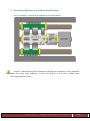
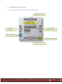
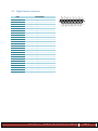
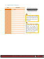
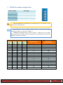
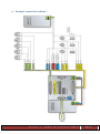
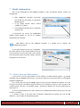
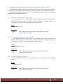
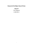
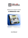
Additional I/O signals module
CSMIO-IO
User Manual
Index
1
General information ................................................................................................................ 3
1.1
Signs used in this guide ................................................................................................... 3
1.2
Standards compliance ..................................................................................................... 4
1.3
Specification .................................................................................................................... 4
2
Safety ....................................................................................................................................... 5
3
Recommendations for mechanical installation ....................................................................... 6
4
Connectors of the device......................................................................................................... 7
4.1
Arrangement of the connectors on the device ............................................................... 7
4.2
Digital inputs connector .................................................................................................. 8
4.3
Digital outputs connector ................................................................................................ 9
4.4
CSMIO-IP connector ...................................................................................................... 10
4.5
Expansion modules connector ...................................................................................... 10
4.6
Power connector ........................................................................................................... 11
5
CSMIO-IO module configuration ........................................................................................... 12
6
Example connection scheme ................................................................................................. 13
7
Mach3 configuration ............................................................................................................. 14
7.1
Mach3’ ports and PIN numbers..................................................................................... 14
7.2
Support for inputs/outputs from the VisualBasic® macros level ................................... 15
7.2.1 SetOutBit – single output switching on ..................................................................... 15
7.2.2
ResetOutBit – single output switching off ................................................................. 15
7.2.3
GetInBit – single input reading .................................................................................. 15
7.2.4
SetModOutput –settings of all module outputs states ............................................ 16
7.2.5
GetInput –reading of all module inputs states ......................................................... 16
CS-Lab s.c. –CSMIO-IO expansion module
Page 2
1 General information
The CSMIO/IP-S control system has standard 32 digital inputs and 16 digital outputs. In more
requiring applications the I/O number may be not enough. Coming up to expectations and
requirements of our clients we designed the CSMIO-IO module. It offers additional 16 digital inputs
and 8 digital outputs. The module communicate with CSMIO/IP through the CAN bus. To the
expansion bus up to 16 CSMIO-IO modules can be connected, so it is easy to count that it’s in the
CSMIO/IP control system you can have max. 288 digital inputs and 144 digital outputs.
There is only one condition: fast signals e.g. HOME switches, LIMIT switches, etc. must be
connected directly to the CSMIO/IP controller.
All module inputs and outputs work in standard industrial 24V power supply voltage and have
full optical isolation with additional protection against short circuit and overheat.
The CSMIO-IO modules are ideal for dispersed systems e.g. –connecting the control panel you
do not need any bundle of cables with separate cable for each button, it will be enough to lead the
CAN bus to the panel with so called „twisted pair-cable”, place the CSMIO-IO in it and connect
switches and controls with short wires.
1.1
Signs used in this guide
__________________________________________________________________________________
Potential danger, possible injury risk.
__________________________________________________________________________________
Useful information, tips
__________________________________________________________________________________
Warning, failure to comply with these warnings may lead to inappropriate functioning or
damage of the device
__________________________________________________________________________________
CS-Lab s.c. –CSMIO-IO expansion module
Page 3
1.2
Standards compliance
CSMIO-MPG modules were designed and made in accordance with the national and
international standards for industrial control systems based on electronic components:
• Detailed requirements for programmable controllers: working characteristics, shock
resistance, safety etc. EN61131-2 (IEC1131-2), CSA 22.2, UL508
• Compliance with European Guidelines (low voltage, the level of electromagnetic interference
Electromagnetic Compability), the CE marking.
• Electrical and non-combustible properties of insulation materials: UL 746C, UL 94, etc.
• The Product made in lead-free technology, RoHS compliant.
1.3 Specification
Parameter
Number of digital inputs
Number of digital outputs
Supply voltage
Power consumption
Maximum voltage on the in/out lines
Maximum load of output line
Connection with CSMIO/IP
Ambient temperature range
Relative humidity
Value
16
8
24VDC +/-10%
2W
30VDC
250mA
CAN 250kbps
0oC do +60oC
10% do 95%
(without condensation)
CS-Lab s.c. –CSMIO-IO expansion module
Page 4
2 Safety
The CSMIO-IO device is powered by 24V safe voltage. I / O control lines are optically isolated,
also the PC connection is galvanically isolated. The device does not constitute a direct threat to the
health and life of the user.
Designing a complete control system (control cabinet), you should draw attention to several
issues, so that the entire system does not pose any hazard during use.
Pay special attention while connecting relays to the control of mains 230V AC. In case of
breakdown on the connector of the module - high voltage may appear. The optical isolation will not
let the voltage to appear on other signals however, you must remember to do all the
installation/service activities while power is off.
CS-Lab s.c. –CSMIO-IO expansion module
Page 5
3 Recommendations for mechanical installation
Here is an example - components arrangement in the control cabinet.
Caution is advised during the mechanical and electrical installation. Poorly tightened
cable may cause many problems, it’s also very difficult to find such a defect while
launching/using the system.
CS-Lab s.c. –CSMIO-IO expansion module
Page 6
4 Connectors of the device
4.1 Arrangement of the connectors on the device
Digital inputs connector
Connector of another
expansion module
Connector for
CSMIO/IP
Module configuration
Power supply connector
Digital outputs connector
CS-Lab s.c. –CSMIO-IO expansion module
Page 7
4.2 Digital inputs connector
PIN
1
2
3
4
5
6
7
8
9
10
11
12
13
14
15
16
17
18
19
20
21
22
23
24
25
Description
Input 0 (+)
Input 2 (+)
Input 4 (+)
Input 6 (+)
Input 0-7 (-)
Input 8 (-)
Input 9 (-)
Input 10 (-)
Input 11 (-)
Input 12 (-)
Input 13 (-)
Input 14 (-)
Input 15 (-)
Input 1 (+)
Input 3 (+)
Input 5 (+)
Input 7 (+)
Input 8 (+)
Input 9 (+)
Input 10 (+)
Input 11 (+)
Input 12 (+)
Input 13 (+)
Input 14 (+)
Input 15 (+)
CS-Lab s.c. –CSMIO-IO expansion module
Page 8
4.3 Digital outputs connector
PIN
1
2
3
4
5
6
7
8
9
10
11
12
13
14
15
16
17
18
19
20
21
22
23
24
25
Description
Outputs 0-3 (+24V) power
supply
Output 0
Output 2
Outputs 4-7(+24V)power supply
Output 4
Output 6
If the 0-3 and 4-7 output
groups are going to be galvanically
separated, you should first use
separate power supply sources for
these groups.
GND
Outputs 0-3(GND) power supply
Output 1
Output 3
Outputs 4-7(GND) power supply
Output 5
Output 7
The outputs have 250mA
permissible load. The outputs
shouldn’t be overload. Pay
attention if large inductance are
connected you may need to use
an additional transient voltage
suppression diode, preferably as
close to the coil as possible.
CS-Lab s.c. –CSMIO-IO expansion module
Page 9
4.4 CSMIO-IP connector
PIN
1
2
3
4
5
6
7
8
9
Description
CAN H
GND
CAN L
RS485 BRS485 A+
-
For proper module working it is enough to connect the lines (CAN H ; CAN
L ; GND) lines (RS485 B- ; RS485A+) are used in other CSMIO modules and their
connection may be required for modules proper working.
4.5 Expansion modules connector
PIN
1
2
3
4
5
6
7
8
9
Description
CAN H
RS232 RxD
RS232 TxD
GND
CAN L
RS485 BRS485 A+
-
Connectors are dedicated exclusively for CS-Lab expansion modules. Do not
connect any other devices, PC, etc.
CS-Lab s.c. –CSMIO-IO expansion module
Page 10
4.6 Power connector
PIN
1
2
3
Description
Module power supply (+24V)
Module power supply (GND)
Ground
View of the plug from the
cables connection side
Pay special attention to not exceed the permissible power voltage (30VDC).
This could damage the device.
CS-Lab s.c. –CSMIO-IO expansion module
Page 11
5 CSMIO-IO module configuration
CONFIG SWITCH
1
2
3
4
5
6
Description
CAN Address (Bit-0)
CAN Address (Bit-1)
CAN Address (Bit-2)
CAN Address (Bit-3)
CAN bus termination
RS485 bus termination
CAN and RS485 lines termination you connect only if it is the only or last
device in the control branch.
CAN address is set in a binary system. Switch “Off” position setting
correspond to logic „0”, and „On” to logic „1”.
CSMIO/IP-S controller adds to the set number – value of 16. In the table
below are listed all possible switches settings and corresponded value and CAN
address seen by the controller.
Switches of address selection position
Dip-Sw
[4]
off
off
off
off
off
off
off
off
on
on
on
on
on
on
on
on
Dip-Sw
[3]
off
off
off
off
on
on
on
on
off
off
off
off
on
on
on
on
Dip-Sw
[2]
off
off
on
on
off
off
on
on
off
off
on
on
off
off
on
on
Dip-Sw
[1]
off
on
off
on
off
on
off
on
off
on
off
on
off
on
off
on
Module number
CAN address
(Mach3 PORT no.)
0
1
2
3
4
5
6
7
8
9
10
11
12
13
14
15
16
17
18
19
20
21
22
23
24
25
26
27
28
29
30
31
CS-Lab s.c. –CSMIO-IO expansion module
Page 12
6 Example connection scheme
CS-Lab s.c. –CSMIO-IO expansion module
Page 13
7 Mach3 configuration
One of the advantages of the CSMIO-IO module is that it practically doesn’t require any
configuration.
•
•
•
After CSMIO/IP-S controller connection
you should turn the power on and launch
Mach3program.
In the „PlugIn Control” menu choose
„CSMIO_IP_P_plugin”
In the diagnostic window go to „Expansion
modules” tab.
If connections are correct, the CSMIO-MPG
module should appear on the list of modules
detected by our controller.
CAN address seen by the CSMIO/IP controller is a number set on module +16
configuration jumpers.
In the same window there is also „IO Module”
tab. After selection of the module address from the
list the preview of current I/O state on the module
and information about eventual outputs overload
will appear on the controls.
7.1 Mach3’ ports and PIN numbers.
If you want to use the inputs/outputs of the module as standard Mach3 signals – eg. spindle
switching or drives ENABLE signal control – you have to enter the correct port and pin in the Mach3
program configuration.
Let’s assume that we want the ENABLE signal to show up on the module with address 31 on the
0 output. You should in the Mach3 program click on the „Config/Ports and pins” menu and go to the
„Output Signals” tab. Next - at „Enable1” signal – activate the „Enable” box, as port number type 31
and as PIN – 0.
As it was mentioned before the port number is just module CAN address and the pin is the I/O
number in a module.
In chapter 5 there is the table with all possible combinations of jumper sets and all CAN
addresses – port number in the Mach3 program.
CS-Lab s.c. –CSMIO-IO expansion module
Page 14
7.2 Support for inputs/outputs from the VisualBasic® macros level
CSMIO-IO module signals can be supported from the scripts level. To facilitate the programmer
work they can be read/saved as VB macros with no need to configure it as standard Mach3 signals.
Signals were assigned to the „ModInputs” and „ModOutputs” registers. They are handled by
using the instructions described below.
7.2.1
SetOutBit – single output switching on
The command causes a single output on the module switching on. You should pay
attention if the output that you want to steer isn’t defined as standard signal in the
„Ports and Pins” menu. If so, the command won’t work correctly.
Syntax:
SetOutBit (addr, bit)
Parameters:
addr
bit
7.2.2
- 100 + address jumpers setting on the module (100-115 range)
- output number (0-7 range)
ResetOutBit – single output switching off
The command causes a single output on the module switching off. You should pay
attention if the output that you want to steer isn’t defined as standard signal in the
„Ports and Pins” menu. If so, the command won’t work correctly.
Syntax:
ResetOutBit (addr, bit)
Parameters:
addr
bit
7.2.3
- 100 + address jumpers setting on the module (100-115 range
- output number (0-7 range)
GetInBit – single input reading
The function turns back „0” or „1” depending on the input state of the CSMIO-IO
module.
Syntax:
GetInBit (addr, bit)
Parameters:
addr
bit
- 100 + address jumpers setting on the module (100-115 range)
- input number (0-15 range)
CS-Lab s.c. –CSMIO-IO expansion module
Page 15
7.2.4
SetModOutput –settings of all module outputs states
Sometimes it is more convenient or even necessary to set all CSMIO-IO module output
states simultaneously. To do this you should use SetModOutput instruction, and enter as
argument „val” the number from the range of numbers 0-255. Bits number state corresponds
to CSMIO-IO module outputs.
Syntax:
SetModOutput (addr, value)
Parameters:
addr
value
7.2.5
- 100 address jumpers setting on the module (100-115 range)
- output state (0-255 range)
GetInput –reading of all module inputs states
Analogously to the previous instruction there is possibility to read all inputs state of the
CSMIO-IO simultaneously. The function turns back the number from the range 0-65535 – bits
returned value corresponds to module inputs states.
Syntax:
GetInput (addr)
Parameters:
addr
- 100 + address jumpers setting on the module (100-115 range)
CS-Lab s.c. –CSMIO-IO expansion module
Page 16