1
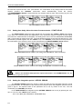
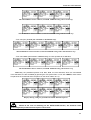
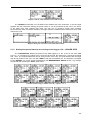
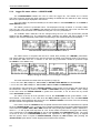
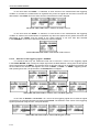
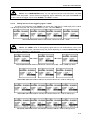
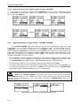
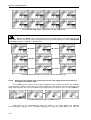
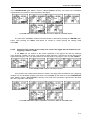
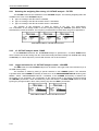
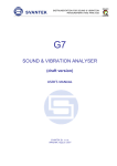
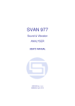
SVAN 953 USER MANUAL
5
MEASUREMENT PARAMETERS SETTING - INPUT
The profile parameters can be set in the INPUT list, which can be entered after pressing
the <MENU> push-button, then selecting by means of the <>, <> (or <>, <>) push-buttons
the INPUT text and finally pressing the <ENTER> one.
Main list with the INPUT text selected
The INPUT list in the LEVEL METER contains the elements which enable one the independent
programming of the measurement parameters (MEASUREMENT SETUP), the input range
(MEASUREMENT RANGE), parameters of three profiles (PROFILE 1, PROFILE 2 and PROFILE 3) and
the trigger function (TRIGGER SETUP).
In the case of the DOSE METER instead of the trigger function there is a DOSEMETER SETUP.
In the case of 1/1 OCTAVE function the SPECTRUM position appears additionally in the INPUT list.
a)
b)
c)
INPUT list in the LEVEL METER (a) 1/1 OCTAVE (b) and DOSE METER (c)
Notice: Any parameter in the INPUT list can be changed only when the instrument
does not execute a measurement. The possibility of a change is signalled by displaying inversely
a parameter’s field. Moreover, normally displayed field means that the parameter cannot be
changed. The “Loudspeaker” icon indicates that the instrument is performing the measurements.
Displays with not active sub-lists of INPUT list
5.1
Selection of measurement parameters - MEASUREMENT SETUP
The MEASUREMENT SETUP is opened after the selection of the MEASUREMENT SETUP text
from the INPUT list by means of the <>, <> (or <>, <> with <SHIFT>) push-buttons and pressing
the <ENTER> one.
The MEASUREMENT SETUP consists of the parameters, which can be set or switched on / off,
namely: the delay of the start of measurements (START DELAY), the integration period
(INTEGR. PERIOD), the repetition of the measurement cycles (REP. CYCLE) and the logger activation or
deactivation (LOGGER). If the logger is active, the user can set the logging period (LOGGER STEP) and
give a name to the logger’s file (LOGGER NAME). In order to change the displayed inversely parameter
5-1
SVAN 953 USER MANUAL
_
the user has to press the <>, <> push-buttons. The confirmation of any change made in the sub-list
requires pressing the <ENTER> push-button, which simultaneously closes the sub-list.
The MEASUREMENT SETUP is closed ignoring any changes made in there, after pressing any time the
<ESC> push-button.
MEASUREMENT SETUP windows
5.1.1
Setting time delay before the start of measurements - START DELAY
The START DELAY defines the delay period from the pressing the <START / STOP> push-button
to the start of the measurements (the digital filters of the instrument analyse constantly the input signal
even when the measurements are stopped). This delay period can be set from 0 second to 60 seconds
(with 1-second step by means of the <>, <> push-buttons and with 10-seconds step with the <>, <>
push-buttons pressed together with the <SHIFT> one). The <ENTER> push-button must be pressed for
the confirmation of the selection, which closes simultaneously the MEASUREMENT SETUP window.
MEASUREMENT SETUP windows; the setting of START DELAY with 1-second step
...
MEASUREMENT SETUP windows; the setting of START DELAY with 10-seconds step
Notice: The minimum delay period is equal to 0 second. In the CALIBRATION mode, the
delay period is equal to 5 seconds.
5.1.2
Setting the integration period - INTEGR. PERIOD
The INTEGR. PERIOD defines the period in which the signal is being averaged during the sound
level measurements. The definitions of the measurement results in which the integration period is used is
given in App. D. The required value of this parameter can be set by means of the <>, <> and
confirmed by the <ENTER> push-button.
In the LEVEL METER the integration period (INTEGR. PERIOD) can be set (by pressing the <>,
<> or <>, <> with <SHIFT> push- buttons):
- From 1 s to 59 s (with 1-second or 10-seconds step).
5-2
SVAN 953 USER MANUAL
MEASUREMENT SETUP windows; INTEGR. PERIOD setting with 1-second step
MEASUREMENT SETUP windows; INTEGR. PERIOD setting with 10-seconds step
- From 1 m (min) to 59 m (with 1-minute or 10-minutes step).
...
MEASUREMENT SETUP windows; INTEGR. PERIOD setting with 1 and 10-minutes step
- From 1 h to 24 h (with 1-hour or 10-hours step). It is also possible to set Inf value.
...
MEASUREMENT SETUP windows; INTEGR. PERIOD setting with 10-hours step
Additionally, the predefined periods: 1 m, 5 m, 15 m, 1 h, 8 h and 24 h, which are enumerated
in the standards, are also available (by pressing the <> push-button or <> with <SHIFT>; these values
are placed in the mentioned above sequence on the left in relation to 1 s).
Displays during setting the predefined INTEGR. PERIOD sequence
Notice: In the case of switching on the AUTO SAVE function, the minimum value
of the integration period should be equal to 10 seconds.
5-3
SVAN 953 USER MANUAL
_
Notice: In the DOSE METER the integration period cannot be set for the value greater than
8 hours.
If the user wants to set AUTO SAVE option (path: MENU / FILE / SAVE OPTIONS / AUTO SAVE)
the integration period value has to be greater or equal than 10 seconds. When AUTO SAVE option was
set and new entered integration period value is less than 10 seconds AUTO SAVE option switches off and
the proper message appears on the display.
Display, when the INT.PERIOD is too short for AUTO SAVE option
5.1.3
Setting the number of repetition of measurement cycles - REP. CYCLE
The REP. CYCLE defines the number of cycles (with the measurement period defined
in the INTEGR. PERIOD) which should be performed by the instrument. The required parameter can
be set by means of the <>, <> push-buttons (with the step equal to 1) or by means of the <>, <>
push-buttons pressed together with the <SHIFT> one (with the step equal to 20). The selected value
is accepted by pressing the <ENTER> push-button, which closes the MEASUREMENT SETUP window.
The Inf value denotes the infinite repetition of the measurements (until the pressing the <START / STOP>
push-button or after receiving the remote control code). The REP. CYCLE number values are within
the limits [1, 1000].
MEASUREMENT SETUP windows; REP. CYCLE setting with the step equal to one
...
MEASUREMENT SETUP windows; REP. CYCLE setting with the step equal to 20
5.1.4
Logger functionality switching On / Off - LOGGER
The LOGGER switches on and off the functionality, which enables the user to save in a file
the selected results from three profiles with the defined period. The LOGGER can be activated and
deactivated by means of the <>, <> push-buttons and accepted by the <ENTER> one.
The acceptation closes simultaneously the MEASUREMENT SETUP window. Any changes are ignored
after pressing the <ESC> push-button.
5-4
SVAN 953 USER MANUAL
Displays with the LOGGER deactivated and activated
The LOGGER functionality is not included in the standard set of the instrument. It can be bought
together with the instrument ordering the proper option or can be purchased by the user in the future.
In the latter case, after selecting On value, the user has to introduce special code activating
the functionality. After successful activation, the logger remains available and the instrument never more
asks for the code.
=>
Displays during the activation of LOGGER functionality
5.1.5
Setting time period between two writings to the logger’s file - LOGGER STEP
The LOGGER STEP defines the period of the data logging in a file. It can be set from 2 ms
to 1 s in 1, 2, 5 sequence, the values from 1 second to 59 seconds, the values from 1 minute to 59 minute
and 1 hour. The required parameter can be set by means of the <>, <> push-buttons with the single
step and by means of the <>, <> with <SHIFT> with the incremented one. The selection is accepted
by the <ENTER> one, which closes simultaneously the MEASUREMENT SETUP window. Any changes
are ignored after pressing the <ESC> push-button.
LOGGER STEP setting; available values in a sequence 1, 2, 5
...
...
...
LOGGER STEP setting; available values from 1 second to 1 hour
5-5
SVAN 953 USER MANUAL
5.1.6
_
Logger file name edition - LOGGER NAME
The LOGGER NAME enables the user to name the logger file. The default one is &LOG.
The name cannot be longer than eight characters including not edited first one character &. After entering
this line, the special help is displayed in the last line.
The name edition is performed similarly to the name edition in the FILE NAME line of the SAVE or
SAVE SETUP window.
The edition process is presented below. The displayed inversely character is currently edited.
The <>, <>, <>, <> and <SHIFT> push-buttons are used for editing the name. One can select the
proper position of the character in the edited text using the <>, <> push-buttons.
The available ASCII characters can be changed using the <> (or <>) push-button pressed
together with the <SHIFT> one. The subsequent digits, underline, big letters and space appear on the
display in the inversely displayed position after each pressing of the mentioned above push-buttons.
LOGGER NAME edition in MEASUREMENT SETUP
The edited name is accepted and the file is saved after pressing the <ENTER> push-button.
The special warning is displayed in the case the file with the edited name already exists in the memory.
The instrument waits then for a reaction of the user (any push-button should be pressed except
the <SHIFT> or the <ALT> one).
=>
=>
Displays during the attempt of overwriting the existing file
The main measurement results from each profile (cf. App. B):
• LPeak, LMax, LMin, SPL, LEQ, Lden, Ltm3, Ltm5, for SOUND LEVEL METER and 1/1 OCTAVE
• LPeak, LMax, LMin, SPL, LEQ, Lden, Ltm3, Ltm5, LAV and TLAV for DOSE METER
are calculated in the period set in the INTEGR. PERIOD. These results can be saved in the result files of
the instrument’s memory by means of the SAVE or SAVE NEXT function (path: MENU / FILE / SAVE)
In the case when the INTEGR. PERIOD is greater than 9 seconds, it can be done also by means
of the AUTO SAVE operation.
The name of the file for that operation is set in the FILE NAME window (path: MENU / FILE /
AUTO SAVE / FILE NAME). In the case when the REP. CYCLE is greater than one, the AUTO SAVE
operation will be performed after the period set in the INTEGR. PERIOD. The name of the file containing
the main results is changed after each saving.
In the same, when the LOGGER is On, the partial measurement results are calculated in the period
set in the LOGGER STEP. Up to 12 results can be logged simultaneously from three independent profiles
of the instrument (PEAK / MAX / MIN / RMS results from each profile (path: MENU / INPUT / PROFILE x,
where x = 1, 2 and 3)) with time step down to 2 ms. These results are saved in one logger’s file memory
of the instrument in the LEVEL METER as well as 1/1 OCTAVE and DOSE METER mode. The name
of the file is set in the LOGGER NAME position. The registration in the logger’s memory is stopped
after the period, which is equal to INTEGR. PERIOD multiplied by REP. CYCLE, after pressing the
<START/STOP> push-button or after stopping the measurements remotely.
5-6
SVAN 953 USER MANUAL
Measurements started by <START/STOP> push-button, ended by last repetition cycle
0
REP. CYCLE
n=1
T
2T
INTEGR. PERIOD INTEGR. PERIOD
T
T
start
AUTO SAVE
@sig1.svn
PEAK, MAX, MIN or RMS
main results
integration period
from 0 to T
time history
REP. CYCLE
n=N-1
AUTO SAVE
@sig2.svn
main results
integration period
from T to 2T
(N-2)T
REP. CYCLE
n=N
(N-1)T
NT
measurements
end
INTEGR. PERIOD INTEGR. PERIOD
T
T
AUTO SAVE
@sigN-1.svn
AUTO SAVE
@sigN.svn
main results
integration period
from (N-2)T
to (N-1)T
time
main results
integration period
from (N-1)T
to NT
main results
files
signal amplitude
REP. CYCLE
n=1
LOGGER: ON
&logger1.svn
RMS results logged
with LOGGER STEP.
Number of results
equal NT / LS
0
LS
LOGGER STEP
NT
time
Relations between INTEGR. PERIOD and LOGGER STEP
5.2
Measurement range info - MEASUREMENT RANGE
The MEASUREMENT RANGE window displays the info about the meter’s measurement range.
In order to open this window the user has to select the MEASUREMENT RANGE text in the INPUT list by
means of the <>, <> push-buttons and press the <ENTER> one. The change of the input range is not
possible. In the SLM mode, the instrument operates in one, wide dynamic range and no other ranges
are available. In 1/1 OCTAVE mode it is possible to choose the HIGH or LOW measurement range (see
chapter dealing with 1/1 OCTAVE function). The detailed description of the measurement range
parameters is given in App. C. The return to the INPUT list is made after pressing the <ESC> or
<ENTER> push-buttons.
a)
b)
INPUT list with the MEASUREMENT RANGE selected (a) and opened (b)
MEASUREMENT RANGE selection in 1/1 OCTAVE analyser
5-7
SVAN 953 USER MANUAL
_
In the case when the level of the measured signal is too low in the relation to the measuring
range (when the level of the input signal is under the linearity of the range declared in App. C, so-called
UNDERRANGE) in one profile mode the message is displayed on the bottom of the display. The arrow
directed down is used for this reason in 3 PROFILES mode.
View of the displays when the level of the signal is too low
5.3
Setting parameters in a profile - PROFILE x
The user enters the PROFILE x sub-list after pressing the <ENTER> push-button on the displayed
inversely PROFILE x text, which has to be selected by means of the <>, <> push-buttons.
In the PROFILE x sub-list the following parameters can be programmed independently for each profile:
weighting filter (FILTER), RMS detector type (DETECTOR) and profile's results logged in a file
(LOGGER PEAK, LOGGER MAX, LOGGER MIN and LOGGER RMS).
INPUT windows; PROFILE 1, PROFILE 2 and PROFILE 3 selected
Notice: The change of the profile parameters is not possible when the measurement
is performed. The user has to finish the current measurement.
5.3.1
• Z
• A
• C
Weighting filter selection in a profile - FILTER
The following weighting filters are available in each profile of the instrument:
type 1 according to the IEC 61672-1 standard,
type 1 according to the IEC 651 and IEC 61672-1 standards,
type 1 according to the IEC 651 and IEC 61672-1 standards.
PROFILE(x) windows; the selection of the weighting filter
The characteristics of the filters are given in App. D. The selection of the required filter is made
with the <>, <> push-buttons. The user can enter the FILTER line in the PROFILE x sub-list pressing
the <>, <> push-buttons. After pressing the <ENTER> push-button any changes made
in the sub-list are confirmed and it is closed. The return to the INPUT list ignoring any changes made
in the sub-list is made after pressing the <ESC> push-button.
5-8
SVAN 953 USER MANUAL
5.3.2
RMS detector selection - DETECTOR
In the instrument three RMS detectors are available: IMPULSE, FAST and SLOW. The selection
of the required detector is made with the <>, <> push-buttons. The user can enter the DETECTOR line
in the PROFILE x sub-list pressing the <>, <> push-buttons. After pressing the <ENTER> push-button
any changes made in the sub-list are confirmed and it is closed. The return to the INPUT list ignoring any
changes made in the sub-list is made after pressing the <ESC> push-button.
PROFILE(x) windows; the selection of the RMS detector
5.3.3
PEAK result selection for saving in a logger’s file - LOGGER PEAK
Up to four measurement results from each profile can be saved in the logger’s file
of the instrument. In order to save the PEAK result (cf. the definition in App. D) the user has to activate
this line (by means of the <>, <> push-buttons) and place a special character in the brackets using
the <>, <> push-buttons.
After pressing the <ENTER> push-button any changes made in the window are confirmed and
it is closed. The return to the INPUT list ignoring any changes made in the window is made after pressing
the <ESC> push-button.
...
PROFILE(x) windows; the PEAK result to be not saved or saved in a logger’s file
5.3.4
MAX result selection for saving in a logger’s file - LOGGER MAX
In order to save the MAX result (cf. the definition in App. D) the user has to activate this line
(by means of the <>, <> push-buttons) and place a special character in the brackets using the <>,
<> push-buttons.
After pressing the <ENTER> push-button any changes made in the window are confirmed and
it is closed. The return to the INPUT list ignoring any changes made in the window is made after pressing
the <ESC> push-button.
...
PROFILE(x) windows; the MAX result to be not saved or saved in a logger’s file
5-9
SVAN 953 USER MANUAL
5.3.5
_
MIN result selection for saving in a logger’s file - LOGGER MIN
In order to save the MIN result (cf. the definition in App. D) the user has to activate this line
(by means of the <>, <> push-buttons) and place a special character in the brackets using the <>,
<> push-buttons. After pressing the <ENTER> push-button any changes made in the window are
confirmed and it is closed. The return to the INPUT list ignoring any changes made in the window is made
after pressing the <ESC> push-button.
...
PROFILE(x) windows; the MIN result to be not saved or saved in a logger’s file
5.3.6
RMS result selection for saving in a logger’s file - LOGGER RMS
In order to save the RMS result (cf. the definition in App. D) the user has to activate this line
(by means of the <>, <> push-buttons) and place a special character in the brackets using the <>,
<> push-buttons.
After pressing the <ENTER> push-button any changes made in the window are confirmed and
it is closed. The return to the INPUT list ignoring any changes made in the window is made after pressing
the <ESC> push-button.
...
PROFILE(x) windows; the RMS result to be not saved or saved in a logger’s file
5.4
Triggering mode and parameters selection - TRIGGER SETUP
The TRIGGER SETUP sub-list is accessible in the LEVEL METER and 1/1 OCTAVE modes and
it is not present in the DOSE METER. This sub-list is opened after the selection of the TRIGGER SETUP
text from the INPUT list by means of the <>, <> (or <>, <> with <SHIFT>) push-buttons and
pressing the <ENTER> one. The TRIGGER SETUP consists of the MEASURE TRIGGER and
the LOGGER TRIGER sub-lists. The return to the INPUT list is made after pressing the <ESC> pushbutton.
<ENTER>
<ESC>
TRIGGER SETUP selected in the INPUT list and the TRIGGER SETUP sub-list
5.4.1
Trigger parameters setting - MEASURE TRIGGER
The MEASURE TRIGGER is a contexts sub-list in which the triggering can be switched off or on
(TRIGGER), in the case when it is switched on - the source of the triggering signal can be determined
(SOURCE), its level (LEVEL) and sometimes also the speed of changes (GRADIENT).
5-10
SVAN 953 USER MANUAL
In order to enter this sub-list the user has to select by means of the <>, <> push-buttons
the MEASURE TRIGGER text in the TRIGGER SETUP sub-list and press the <ENTER> one.
...
...
...
Displays in the MEASURE TRIGGER window
In order to change the displayed inversely parameter the user has to press the <>, <> pushbuttons. The confirmation of any change made in the window requires pressing the <ENTER> pushbutton, which simultaneously closes the current display. The MEASURE TRIGGER window is closed
ignoring any changes made, after pressing any time the <ESC> push-button.
5.4.1.1
Switching the triggering on and off - TRIGGER
The triggering of the measurements (TRIGGER) can be switched off using the <> push-button.
MEASURE TRIGGER window
The triggering is switched on if one of its five modes is selected: SLOPE +, SLOPE –, LEVEL +,
LEVEL - or GRAD +. The selection of the triggering mode is performed using the <>, <> push-buttons.
If the instrument works with the triggering switched on the “Antenna” icon is flashing on the display in the
case when the triggering condition was not fulfilled.
Displays during the measurements while the triggering condition is not fulfilled
In the case when the SLOPE + is selected, the measurement starts when the arising signal will
pass the level determined in the LEVEL. In the case when the SLOPE – is selected, the measurement
starts when the falling down signal will pass the level determined in the LEVEL. The measurement
is stopped when the conditions set in the MEASUREMENT SETUP sub-list are fulfilled, after pressing
the <START / STOP> push-button or after receiving the proper control code remotely.
MEASURE TRIGGER windows with SLOPE modes selected
In the case when the LEVEL + is selected, in each second of the measurement the triggering
condition is checked; the measurement is registered only when the signal has the greater level than this
determined in the LEVEL and in the other case the measurement result is skipped.
5-11
SVAN 953 USER MANUAL
_
In the case when the LEVEL – is selected, in each second of the measurement the triggering
condition is checked; the measurement is registered only when the signal has the lower level than this
determined in the LEVEL and in the other case the measurement result is skipped.
MEASURE TRIGGER windows with LEVEL modes selected
In the case when the GRAD + is selected, in each second of the measurement the triggering
condition is checked; the measurement is registered only when the signal has the greater level than this
determined in the LEVEL and the speed of the signal changes is not less than that selected
in the GRADIENT. In the other case the measurement result is skipped.
MEASURE TRIGGER window with GRAD + mode selected
5.4.1.2
Selection of the triggering signal - SOURCE
It is assumed that only one measured result can be used as a source of the triggering signal
in the LEVEL METER mode, namely the output signal from the RMS detector coming from the first profile
which is denoted here as RMS(1). This position does not become active (it is not displayed inversely) and
the text stated here remains unchanged in the case of LEVEL +, LEVEL - or GRAD + triggering mode.
After pressing there the <> push-button, the SOURCE line is skipped.
<
>
<
>
...
<
>
MEASURE TRIGGER windows with not active SOURCE signal line
In the case of SLOPE + and SLOPE – as a source of the triggering signal can be used the signal
connected to the external input/output socked named Ext.I/O. The selection of the source of the triggering
signal is performed using the <>, <> push-buttons.
...
MEASURE TRIGGER window with SOURCE signal selection
5-12
SVAN 953 USER MANUAL
Notice: In the LEVEL METER mode, only one signal measured in the instrument - the RMS
detector of the first profile - can be used as the triggering signal. Additionally, the signal from Ext.I/O can
be also used as the trigger source in the SLOPE + and SLOP – modes.
5.4.1.3
Setting the level of the triggering signal - LEVEL
The level of the triggering signal (LEVEL) can be set with 1-dB step (or 10-dB steps) from 24 dB to
136 dB range using the <>, <> push-buttons (or <>, <> with <SHIFT>).
...
...
MEASURE TRIGGER window with LEVEL selection in SLOPE + mode
Notice: The LEVEL value of the triggering signal refers to the instantaneous value of the
RMS result from the first profile calculated during the period depending on selected DETECTOR (path:
MENU / INPUT / PROFILE 1 / DETECTOR).
<
>+<SHIFT>
<
>+<SHIFT>
MEASURE TRIGGER window with LEVEL selection in SLOPE – mode (10-dB step down)
<
>
<
>
MEASURE TRIGGER window with LEVEL selection in LEVEL + mode (1-dB step up)
MEASURE TRIGGER window with LEVEL selection in LEVEL – mode (1-dB step up)
MEASURE TRIGGER window with LEVEL selection in GRAD + mode (1-dB step down)
5-13
SVAN 953 USER MANUAL
5.4.1.4
_
Setting the speed of the triggering signal changes - GRADIENT
The speed of the triggering signal changes (GRADIENT) can be set with 1-dB/millisecond step
(or 10-dB/millisecond steps) from 1 dB/ms to 100 dB/ms range using the <>, <> push-buttons
(or <>, <> with <SHIFT>).
<>
<>+ <SHIFT>
MEASURE TRIGGER window with GRADIENT selection (1-dB/ms and 10-dB/ms step up)
<>+<SHIFT>
<>
MEASURE TRIGGER window with GRADIENT selection (10-dB/ms up and 1-dB/ms down)
5.4.2
Trigger parameters in logger setting - LOGGER TRIGGER
The LOGGER TRIGGER parameters influence the way the measurement results are saved
in the logger. It is a contexts sub-list in which the triggering in logger can be switched off or on
(TRIGGER). In the case when it is switched on, i.e. the LEVEL + mode - the source of the triggering
signal is determined (SOURCE), its level can be selected (LEVEL), the number of the results saved in the
logger before the fulfilment of the triggering condition (PRE) and the number of the results saved in the
logger after the fulfilment of the triggering condition (POST). If the triggering signal is greater than the
selected in the LEVEL, the logger contains:
• the measurement results registered directly before the fulfilment of the triggering condition; time
of the registration can be calculated by multiplying the value set in the PRE by the value taken from
the LOGGER STEP (path: MENU / INPUT / MEASUREMENT SETUP / LOGGER STEP);
• all measurement results up to the moment the triggering signal falls down the LEVEL;
• the results registered directly after the fulfilment of the triggering condition; time of the registration can
be calculated by multiplying the value set in the POST by the value taken from the LOGGER STEP
(path: MENU / INPUT / MEASUREMENT SETUP / LOGGER STEP).
Notice: The LOGGER TRIGGER functionality is not included in the standard functionality
of the SVAN 953 instrument. It is available as an option, which is activated after entering special code.
The code should be introduced only once. If the option is activated the ENTER CODE window is not
displayed any more.
<ENTER>
<>
TRIGGER SETUP window; LOGGER TRIGGER selection
5-14
SVAN 953 USER MANUAL
In order to change the displayed inversely parameter the user has to press the <>, <> pushbuttons. The confirmation of any change made in the window requires pressing the <ENTER> pushbutton, which simultaneously closes the current display. The LOGGER TRIGGER window is closed
ignoring any changes made, after pressing any time the <ESC> push-button.
5.4.2.1
Switching the logger triggering on and off - TRIGGER
The logger triggering of the measurements (TRIGGER) can be switched off using the <> pushbutton (or <> with <SHIFT>). The triggering is switched on if the LEVEL + or LEVEL- mode is selected
using the <> push-button (or <> with <SHIFT>).
<
>
<
>
LOGGER TRIGGER windows
5.4.2.2
Selection of the triggering signal in logger - SOURCE
It is assumed that only one measured result can be used as a source of the triggering signal
in the logger of the LEVEL METER mode, namely the output signal from the RMS detector coming from
the first profile which is denoted here as RMS(1). This position does not become active (it is not displayed
inversely) and the text stated here remains unchanged. After pressing the <> push-button, the SOURCE
line is skipped.
<
>
LOGGER TRIGGER windows with not active SOURCE signal line
However, in 1/1 OCTAVE analysis it is possible to access mentioned above position and to make a
selection. The results coming from the output of 1/1 OCTAVE filters, starting from 125 Hz (125 Hz,
250 Hz, 500 Hz, 1.00 kHz, 2.00 kHz, 4.00 kHz, 8.00 kHz and 16.0 kHz), are available as well as RMS
result from the first profile. Other TRIGGER SETUP sets are identical as for the SLM.
..
..
LOGGER TRIGGER window with SOURCE selection in 1/1 OCTAVE mode
5.4.2.3
Setting the level of the triggering signal in the logger - LEVEL
The level of the triggering signal in logger (LEVEL) can be set in 1-dB step (or 10-dB steps)
from 24 dB to 136 dB range using the <>, <> push-buttons (or <>, <> with <SHIFT>).
5-15
SVAN 953 USER MANUAL
_
LOGGER TRIGGER window with LEVEL selection (1-dB step up)
Notice: The LEVEL value of the triggering signal in logger refers to the instantaneous value
of the RMS result from the first profile calculated during the period depending on selected DETECTOR
(path: MENU / INPUT / PROFILE 1 / DETECTOR).
<
>+<SHIFT>
<
>+<SHIFT>
...
<
>+SHIFT>
<
>+<SHIFT>
<
>+ SHIFT>
<
>+ <SHIFT>
LOGGER TRIGGER window with LEVEL selection (10-dB step up)
5.4.2.4
Selection of the number of the results to be saved in the logger before the fulfilment of
the triggering condition - PRE
In the PRE line the number of the results registered in the logger’s file before the fulfilment
of the triggering condition can be set. This number is within the limits 0..50 and can be set with the step
equal to one using the <>, <> push-buttons or the step equal to 10 using the <>, <> with <SHIFT>.
=>
<
>
...
LOGGER TRIGGER windows with PRE selection
Time period of the measurements which are saved in the logger before the fulfilment
of the triggering condition can be calculated multiplying the value set in the PRE by the value set
5-16
SVAN 953 USER MANUAL
in the LOGGER STEP (path: MENU / INPUT / MEASUREMENT SETUP). The result of the calculation
is presented in the same line, at the right side of the display.
=>
...
=>
=>
LOGGER TRIGGER windows with PRE selection for different LOGGER STEPS
The value set in the PRE is confirmed and the window is closed after pressing the <ENTER> pushbutton. After pressing the <ESC> push-button the window is closed ignoring the settings made
in the PRE.
5.4.2.5
Selection of the number of the results to be saved in the logger after the fulfilment of the
triggering condition - POST
In the POST line the number of the results registered in the logger’s file after the fulfilment
of the triggering condition can be set. This number is within the limits 0..200 and can be set with the step
equal to one using the <>, <> push-buttons or the step equal to 10 using the <>, <> with <SHIFT>.
<
>
=>
...
LOGGER TRIGGER windows with POST selection
Time period of the measurements which are saved in the logger after the fulfilment of the triggering
condition can be calculated multiplying the value set in the POST by the value set in the LOGGER STEP
(path: MENU / INPUT / MEASUREMENT SETUP). The result of the calculation is presented in the same
line, at the right side of the display.
=>
...
=>
=>
LOGGER TRIGGER windows with POST selection for different LOGGER STEP
5-17
SVAN 953 USER MANUAL
_
The value set in the POST is confirmed and the window is closed after pressing the <ENTER>
push-button. After pressing the <ESC> push-button the window is closed ignoring the settings made
in the POST.
5.5
Selection of dose meter parameters - DOSEMETER SETUP
The DOSEMETER SETUP is accessible in the INPUT list in the DOSE METER mode but
it is not present in the LEVEL METER or 1/1 OCTAVE mode. This sub-list is opened after the selection
of the DOSEMETER SETUP text from the INPUT list by means of the <>, <> (or <>, <>) pushbuttons and pressing the <ENTER> one.
The DOSEMETER SETUP consists of the parameters, which influence the calculation of the dose
meter results: the CRITERION LEVEL, THRESHOLD LEVEL and EXCHANGE RATE (the definitions of
the dose meter results are given in App. D).
<ENTER>
DOSEMETER SETUP selected in INPUT list and the DOSEMETER SETUP window
5.5.1
Setting criterion sound level - CRITERION LEVEL
The criterion sound level influences the calculations of the DOSE and D_8h results.
The
CRITERION LEVEL
line
is
accessible
after
pressing
the
<>
push-button
in the DOSEMETER SETUP window.
The available values are as follows: 80 dB, 84 dB, 85 dB or 90 dB. They can be selected by means
of the <>, <> push-buttons. The confirmation of any change made in the line requires pressing
the <ENTER> push-button, which simultaneously closes the window. The DOSEMETER SETUP is closed
ignoring any changes made in there, after pressing any time the <ESC> push-button.
DOSEMETER SETUP windows with CRITERION LEVEL selection
5.5.2
Setting criterion sound level - THRESHOLD LEVEL
The threshold level influences the calculations of the dose meter results, namely DOSE, D_8h and
LAV. The THRESHOLD LEVEL line is accessible after pressing the <>, <> push-buttons
in the DOSEMETER SETUP window.
The available values are as follows: None, 75 dB, 80 dB, 85 dB or 90 dB. They can be selected by
means of the <>, <> push-buttons. The confirmation of any change made in the line requires pressing
the <ENTER> push-button, which simultaneously closes the window. The DOSEMETER SETUP is closed
ignoring any changes made in there, after pressing any time the <ESC> push-button.
5-18
SVAN 953 USER MANUAL
<
>
<
>
<
>
<
>
DOSEMETER SETUP windows with THRESHOLD LEVEL selection
5.5.3
Setting criterion sound level - EXCHANGE RATE
The exchange rate influences the calculations of the dose meter results, namely DOSE, D_8h and
LAV. The exposure rate equal to three complies with ISO R 1999 “Assessment of Occupational Noise
Exposure for Hearing Conservation Purposes”, while equal to five complies with the American
“Occupational Safety and Health Act” – OSHA.
The EXCHANGE RATE line is accessible after pressing the <> push-button in the
DOSEMETER SETUP widow.
The available values are as follows: 2, 3, 4 or 5. They can be selected by means of the <>, <>
push-buttons. The confirmation of any change made in the line requires pressing the <ENTER> pushbutton, which simultaneously closes the window. The DOSEMETER SETUP is closed ignoring any
changes made in there, after pressing any time the <ESC> push-button.
DOSEMETER SETUP windows with EXCHANGE RATE selection
5.6
Selection of 1/1 octave spectrum parameters - SPECTRUM
The SPECTRUM appears in the INPUT list when the 1/1 OCTAVE function is selected
in the MEASUREMENT FUNCTION (path: MENU / FUNCTION / MEASUREMENT FUNCTION /
1/1 OCTAVE). This sub-list is opened after the selection of the SPECTRUM text from the INPUT list
by means of the <>, <> (or <>, <>) push-buttons and pressing the <ENTER> one.
The SPECTRUM consists of the parameters, which influence the calculation and logging the results
of 1/1 OCTAVE analysis: FILTER, BAND and LOGGER. The SPECTRUM window is closed ignoring any
changes made in there, after pressing any time the <ESC> push-button.
<ENTER>
SPECTRUM selected in INPUT list and SPECTRUM window opened
5-19
SVAN 953 USER MANUAL
5.6.1
_
Selecting the weighting filter during 1/1 OCTAVE analysis - FILTER
The FILTER influences the calculations of 1/1 OCTAVE analysis. The following weighting filters are
available in the case of 1/1 OCTAVE analysis:
•
Z
type 1 according to the IEC 61672-1 standard,
•
A
type 1 according to the IEC 651 and IEC 61672-1 standards,
•
C
type 1 according to the IEC 651 and IEC 61672-1 standards.
The selection of this parameter is made by means of the <>, <> push-buttons.
The confirmation of the change made in the line requires pressing the <ENTER> push-button, which
simultaneously closes the window. The frequency characteristics of those filters are given in Appendix D.
SPECTRUM windows with FILTER selection
5.6.2
1/1 OCTAVE analysis band - BAND
In the SVAN 953 instrument the 1/1 OCTAVE analysis is performed in, so-called, AUDIO band,
which contains the results coming from ten consecutive band-pass filters starting from 31.5 Hz and ending
at 16.0 kHz (1/1 octave sequence). The line with this text can not be accessed.
5.6.3
Logger activation for 1/1 OCTAVE analysis results - LOGGER
The RMS result from 1/1 OCTAVE analysis can be saved in the logger’s file of the instrument (or on
the USB memory stick).
The activation is made by placing a special character in the LOGGER position. The activation
is possible when the LOGGER functionality is switched on in the MEASUREMENT SETUP window (path:
MENU / INPUT / MEASUREMENT SETUP / LOGGER). If the LOGGER functionality is switched off,
the position is not accessible. The confirmation of the change made in the position requires pressing
the <ENTER> push-button, which simultaneously closes the window. The SPECTRUM window is closed
ignoring any changes made in there, after pressing any time the <ESC> push-button.
<
>
SPECTRUM windows with LOGGER activation
5-20