1
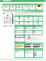
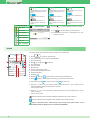
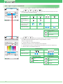
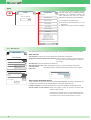
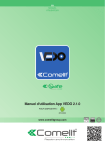
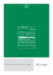
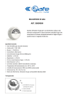
EN USER MANUAL ON 1 2 3 4 5 6 User manual for Serial Bridge Art. 20003101 www.comelitgroup.com INDEX Introduction............................................................................................................................................................. 3 Access to Web pages............................................................................................................................................. 3 Description of the interface ................................................................................................................................... 3 Alarm (for VEDO control panels) .......................................................................................................................... 4 Climate..................................................................................................................................................................... 5 Other / Lights / Irrigation / Automations ............................................................................................................... 6 Shutter ..................................................................................................................................................................... 7 Consumption .......................................................................................................................................................... 7 Scenarios ................................................................................................................................................................ 7 Setup ....................................................................................................................................................................... 8 Setup / Date and Time ........................................................................................................................................................... 8 Setup / Timer enabling ........................................................................................................................................................... 9 Setup / Consumption ............................................................................................................................................................. 9 Setup / Consumption / Display ......................................................................................................................................... 9 Setup / Consumption / Setpoints ................................................................................................................................... 10 Setup / Consumption / Rates .......................................................................................................................................... 10 Setup / Consumption / Settings ..................................................................................................................................... 10 Setup / Consumption / Reset .......................................................................................................................................... 10 Setup / User Codes............................................................................................................................................................... 11 Setup / Dynamic DNS ........................................................................................................................................................... 11 2 Introduction The multifunctional Serial Bridge module makes it possible to communicate with the SimpleHome home automation system and with S-Series and VEDO anti-intrusion systems. It can be used as follows: • Weekly schedule programming: sends commands to outputs, zones, scenarios and thermostats within the system. • Rule management: programs logic rules for the generation of an event. • Scenario management: programs scenarios for sending commands to the SimpleHome automation system and/or the S-Series or VEDO security system. • Management via browser: allows the user to directly access the security and home automation systems from an internet browser, in order to control the security system or the automation system by means of simple commands. Configuration must take place via the WEB interface. Access to Web pages To access the Web pages via browser (from PC, tablet, smartphone...): Local connection: 1. Open your browser. 2. Enter the address 192.168.1.252 (or the IP address provided by your installer) in the address bar and press enter. 3. If requested, enter the user password provided by your installer (default = 111111) and confirm. Remote connection: 1. Open your browser. 2. Enter the hostname provided by your installer (e.g. "XXXXXX.comelitdns.com") in the address bar and press enter. 3. If requested, enter the user password provided by your installer (default = 111111) and confirm. Description of the interface bridge 1 0.00kW 17:14 - 07/04/2014 2 3 Alarm Climate Other Shutters Lights Irrigation Automations Consumption 1. Current page header. 2. "Date and consumption" toolbar. 3. Buttons for accessing the internal pages used to view and control the available functions and to configure the device. 4. Connection and authentication status message (connected, not authenticated, not authorised...). 5. Logout button. Press Alarm/Climate/Other.... to access the respective sections. Press to return to the initial screen. Press to return to the previous screen. Setup 4 Connected 5 The menu icons change depending on the type of system installed and the functions available. To navigate the menu, simply press the icon corresponding to the desired function. The icons on the home screen provide feedback on the status of the active elements within the relevant section: Status of the icons on the home screen no active element some active elements all elements active 3 Climate Other Shutters Lights Irrigation Automations Scenarios Climate Other Shutters Lights Sprinkler Automations Scenarios Climate Other Shutters Lights Irrigation Automations Scenarios Status of the "alarm" icon on the home screen Alarm Alarm Alarm Alarm Alarm Alarm Alarm deactivated across the entire system Alarm activated across the entire system Alarm partially activated: only a few areas and/ or a few partial settings are active Sabotage/fault Alarm memory? In alarm Alarm (for VEDO control panels) The Alarm section can be used to activate, deactivate and view the status of the alarm system areas. Alarm This chapter illustrates "alarm" section operation for VEDO series control panels. The display looks different for S-series control panels. 1 (1) Alarm system status icon System Deactivated Status Zones P1 P2 1A P1+P2 Area 1 Deactivated Intrusion Zones P1 P2 System Deactivated System Activated Alarm deactivated Alarm activated across the entire system 2 Partial Activation Alarm partially activated: only a few areas and/or a few partial settings are active 2A P1+P2 Area 2 Deactivated Alarm in progress Alarm Memory Alarm in memory alert In sabotage System in sabotage Alarm in progress (1A) Alarm control buttons for the entire system Connected Status Zones Deactivates the alarms activated across the entire system Displays the status of zones across the entire system (open, omitted, isolated, sabotaged/faulty, in alarm) P1 Activates the alarms across the entire system P2 Activates partial 1 across the entire system (and deactivates partial 2, if active) P1+P2 Activates partial 2 across the entire system (and deactivates partial 1, if active) Status Press Zones entire system. Alarm Open Activates partial 1 and 2 across the entire system to view the status of zones across the to scroll through the zone statuses (open, Use omitted, isolated, sabotaged/faulty, in alarm). (QWUDQFHGRRU Press an entry on the list (e.g.: "Entrance door") to "omit" or "isolate" the zone. Connected (2) Zone alarm status bar Area 1 Area 1 Deactivated Area 1 Total Act. Zone alarm deactivated Zone alarm activated Area 1 Area 1 In sabotage Act. P1 Partial zone alarm activated Area 1 Alarm memory Area in sabotage Zone alarm in memory alert Alarm in progress Alarm in progress (2A) Alarm control buttons for an area Intrusion Zones Deactivates the alarms activated in a specific area Displays the status of zones across the area (open, omitted, isolated, sabotaged/faulty, in alarm, in fault) Activates the alarms for a specific area Indicates that the alarms are active Indicates that the system is not ready for activation, and forcing is required 4 P1 Activates partial 1 across a specific area (and deactivates partial 2, if active) P1 Activates partial 2 across a specific area (and deactivates partial 1, if active) P2 Indicates that the partial set is active Indicates that the partial set is active P2 P1 Indicates that the system is not ready for activation, and forcing is required zone status legend P1+P2 P2 P1+P2 Indicates that the partial sets are active P1+P2 Indicates that the system is not ready for activation, and forcing is required Intrusion Zones Press Intrusion Zones Activates partial 1 and 2 across a specific area Indicates that the system is not ready for activation, and forcing is required to view the status of zones in an area. Zone open Area 1 Zone faulty Zone isolated Use Press an entry on the list (e.g.: "Entrance door") to "omit" or "isolate" the zone. Entrance door Zone excluded Zone in standby to scroll through the system partitions. Connected Zone error Zone in sabotage Climate 1 The climate section can be used to monitor and adjust room temperatures. 2 Climate BATHROOM 24.6°C 24.6°C 10 9 21.2°C + 3 A 4 M 5 ON 6 LIVING ROOM 23.6°C BEDROOM 23.7°C Connected Press Climate to access the Climate menu. Press the desired room (for example: BATHROOM). 1. Room temperature. 2. 3. 4. 5. 6. 7. 8. 9. Boiler / air-conditioning on indicator. Room displayed. Automatic mode. Manual mode. Forcing of timed custom mode. Room temperature adjustment slider. Desired temperature. System on / off. 10. Summer 8 / winter mode selection (cooling / heating management). 7 Press ON (system on) to change the status to Press summer mode OFF to switch to winter mode (system off) and vice-versa. and vice-versa. Press the M icon to set the climate to manual mode and use the + and – selectors (or the adjustment slider) to adjust the temperature of the room. » The icon will turn blue Press the A icon to set the climate to automatic mode and use the programming set on the master supervisor. » The icon will turn blue indicates that timed custom mode has not been activated on the master supervisor. indicates that timed custom mode has been activated on the master supervisor. Options: "Automatic mode", "Manual mode" and "Forcing timed custom mode" are not available if the Serial Bridge is set as a main device (MASTER). 5 Other / Lights / Irrigation / Automations The Other / Lights / Irrigation / Automations section can be used to control the corresponding elements. Lights OFF DAY ZONE ON OFF NIGHT ZONE ON OFF GARDEN ON Other Lights Press / / Irrigation / the zones using the ON /OFF commands. Automations to access the relevant sections and control Element statuses T all elements are off Connected some controlled elements in the room (e.g. DAY ZONE) are active all controlled elements in the room (e.g. DAY ZONE) are active T single active element Irrigation legend Irrigation T timed irrigation Lights Other Lights Press / to access the relevant sections, press a specific room (for example: DAY ZONE) and control the individual elements using the ON/OFF commands. DAY ZONE OFF ENTRANCE LED ON If there is an adjustment slider: move the slider [1] to set the desired intensity. OFF SITTING ROOM2 LED ON If RGB lights are used, their colour and brightness can be adjusted: Click the element you wish to set [2] and select the desired tone on the colour spectrum [3]. Move the slider to set the desired intensity [4]. 4 3 Element statuses element off OFF SITTING ROOM ENTRANCE LED T T T ON 1 OFF T single active element T ON lights legend other outputs legend Connected T other lights timed other RGB lights T 6 timed light Shutter The Shutters section can be used to open or close one shutter or all the shutters in a room. Shutters 1. Press DAY ZONE Shutters to access the shutters section. to close the shutters in the controlled room, and press 2. Press Or to open the shutters in the controlled room, and press Press to stop downward movement. to stop upward movement. Connected The blue bar indicates that the shutters in the controlled zone are working. DAY ZONE Shutters DAY ZONE 1. Press Shutters to access the shutters section. 2. Press a specific room (for example: DAY ZONE) and control the individual elements using AWNING Connected Press Or to close the shutter, and press Press to open the shutters in the controlled room, and press . to stop downward movement. to stop upward movement. The blue bar indicates that the shutter in the controlled zone is working. DAY ZONE The blue arrow indicates whether the shutter is opening or closing. Consumption This menu can be used for monitoring consumption though graphs and tables. Consumption 1 LOADS 2 3 14/04/2014 Day 596.0 Wh 4 Graph 572W 1.50kWh 5 6 476.8 7 357.6 238.4 8 119.2 0 4 8 12 2 16 20 Connected Press 1. 2. 3. 4. 5. 6. 7. 8. Consumption to access the Consumption menu. Scroll through available meters. Meter currently displayed. Scroll through days / months / years / log. Change day / month / year / log mode. Change unit of measurement. Change graph / table display. Total consumption value for the displayed graph. Instant load consumption value. If the maximum consumption setpoints have been set (see Setup/Consumption/Setpoints), the consumption limits are displayed: • In "graph" mode: yellow line from 75% to 100%, red line over 100%. • In "table" mode the check boxes are coloured to indicate the consumption level. Period kWh 0-1 0.001 from 0% to 75% 1-2 475.0 from 75% to 100% 2-3 596.0 over 100% Scenarios Scenarios The Scenarios section can be used to activate programmed scenarios. Press the scenario to activate it. Relax TV Morning Start Tour Relax TV 7 the blue bar indicates that the scenario is being executed. Setup Configuration bridge Setup 17:14 - 07/04/2014 17:14 - 07/04/2014 Enter User Password Date and time Enable Timers Consumption User codes This menu can be used to configure the date and time, enable timers (configured via Setup/ Advanced), set consumption setpoints and rates, change the user code, set a dynamic DNS address and access advanced settings. 1. Press Setup to access the menu. 2. Enter the user password (default = 111111) and confirm. 3. Select the menu entry you want to configure. Dynamic DNS Advanced Firmware: IP address: 172.24.2.186 Subnet Mask: 255.255.0.0 Gateway: 172.24.255.254 Primary DNS: 172.24.0.30 Secondary DNS: 172.24.0.44 MAC address: 00:04:A3:CE:D5:75 Connected Setup / Date and Time This menu can be used to set the device date and time, as well as the Astronomical dawn/dusk device. Date and time Date and time Date and time: the values can only be changed when enable NTP is deactivated. Date and time Date and time DD/MM/YYYY Enable NTP (automatic time/date from Internet): enables automatic updating of date and time via the web. Only works if the bridge is connected to the Internet. 14/04/2014 HH:MM 10:01 Enable NTP (automatic time/date from Internet) Time difference: select the reference time difference. Time difference (GMT +1:00) Rome, Brussels. Copenhag Automatic switch to DST: select "Automatic (Europe only)" to set the automatic switch to DST. (only with enable select "Specify date" to specify the time interval in which DST is applied. NTP active) Automatic switch to DST ƵƚŽŵĂƟĐ;ƵƌŽƉĞŽŶůLJͿ Astronomical dawn/dusk device Sunrise: 06:34 - Sunset: 20:05 Automatic switch to DST Use the stop as a decimal point Specify p y date Latitude: 45.8782 N Longitude: 9.9746 E Sunrise variation: 0min Sunset variation: 0min Save From: 15 / 3 To: 15 / 9 Astronomical dawn/dusk device Sends commands at sunset and sunrise (see Setup/Advanced/Rules), according to the latitude and longitude of the installation site (to avoid installation of external dawn/dusk devices). Latitude / Longitude: set the relevant coordinates for automatic updating of the dawn/dusk clock. Sunrise variation / Sunset variation: adjust these values to bring the sunrise and sunset times forward or set them back. For example: if you want to switch on the outside lights at sunset, leave the sunset variation at 0. If you want to switch them off 2 hours before sunrise, set the sunrise variation to -120 min. 8 Setup / Timer enabling This menu can be used to activate/deactivate the programmed timers and change timer operating times/days. Timer number: select the timer you want to activate (programmed via Setup/Advanced/Timers). Enable Timers Timer enabling: enables the selected timer. "Day" timer Timer number: 2 - Day Timer start: timer start time. The timer start times can be changed. Timer enabling: Enabled days: days on which the timer will be started. The timer operating days can be changed. Timer start: HH:MM Enabled days: Th Mo Fr Timer End: HH:MM Enabled days: Th Mo Fr 00:00 Tu Sa We Su N.B.: with the "virtual timer", the "Timer end" times can also be changed. 00:00 Tu Sa We Su Save Setup / Consumption This menu can be used to set which consumption values to display on the consumption menu, decide which consumption value to display on the homepage, change the maximum consumption setpoints by hour, day, month or year; change the rates by day and time band. Consumption Toolbar: select which meter to monitor via the toolbar on the homepage. Display Currency: enter the currency symbol you want to set for calculating consumption. Thresholds CO2 constant: enter the CO2 constant to monitor the CO2 not released into the atmosphere, in the case of energy production systems (photovoltaic systems...). The "CO2 Saved" graph can be viewed via Home/Consumption. Rates ^ĞƫŶŐƐ HOME / CONSUMPTION / CO2 SAVED Reset Consumption HOME CO2 Saved bridge Toolbar: 17:14 - 07/04/2014 None Currency: Day Graph kg 0kg € CO2 constant: 14/04/2014 0.00kW 0,000 kg/kWh 0.53100 Save 0 4 8 12 16 20 Setup / Consumption / Display Display meters Description: Visibility Electricity Gas Water Input 2 Input 3 Save 9 This menu can be used to rename the meters connected to the system and select the meters that you wish to view in the consumption menu area. Description: description associated with the meter. Visibility: makes the meter in the consumption menu visible. Setup / Consumption / Setpoints This menu can be used to set the maximum consumption setpoints for hours, days, months and years in order to obtain an immediate visual comparison on the graph and in the consumption table when the set setpoint for the period is exceeded. Yellow = 75% of the set setpoint, Red = 100% of the set setpoint. Thresholds "Consumption" thresholds Meter: Meter: select the meter for which you want to set the setpoints. ĐŽŶƐƵŵƉƟŽŶ Time 0.00000 kWh Day 0.00000 kWh Month 0.00000 kWh Year 0.00000 kWh Time/Month/day/Year: set the maximum consumption setpoint for the corresponding time interval. Save Setup / Consumption / Rates This menu can be used to set the meter rates according to time bands. The information will then be used to construct the consumption graphs in the Consumption menu (Home/Consumption). 1. Meter: select the meter for which you want to set the setpoints, for example: "Elect. consumption". 2. Rates: set the rates according to time. 3. Time slot: set the start and end of each time band, and associate the time bands with the corresponding rate for every day of the week. Rates Rate: "Electricity production" Meter: ůĞĐƚ͘ĐŽŶƐƵŵƉƟŽŶ Rates 1 0.09800 €/kWh 2 0.00000 €/kWh 3 0.00000 €/kWh 4 0.00000 €/kWh 5 0.00000 €/kWh CAUTION: daily rate programming must refer to the whole 24-hour cycle; any hours not programmed by the user will be set by the system automatically. Select a rate Time slot: Start: End Mon Tue Wed Thur Sat Sun 0 6 1 1 1 1 1 2 2 6 20 1 1 1 1 Fri 1 2 2 20 24 2 2 2 2 2 2 2 Save Setup / Consumption / Settings This menu can be used to view the settings for the pulse meter module used to measure water, GAS, etc...). Meter: select the meter for which you want to change the settings. Settings Unit of measurement: enter the unit of measurement for that meter. "GAS" settings Meter: GAS Unit of measurement: Scale factor: mc Scale factor: enter a multiplication factor if you want to convert different units of measurement (for example, from litres to imperial gallons, 4.54609). 1.00000 Save Setup / Consumption / Reset Reset count 17:14 - 07/04/2014 Reset meters: are you sure? No Yes 10 This menu can be used to reset all meters. Press "Yes" to reset all meters. Setup / User Codes This menu can be used to change the user code: Change codes Home automation login Serial Bridge user code New user code: Re-enter user code: Save Connected √ The code can consist of letters a-z (capitals or lower case) and/or digits 0-9. √ The password is case-sensitive (a difference is detected between capitals and lower case letters). √ Min. length 4 characters - Max. 10 characters. Home automation login: the drop-down menu can be used to set the "Home automation login" as: S-series control panels VEDO control panels no user code (default): to access all "user sections" (except SetUp and Alarms) without entering the user password. A user password should nevertheless be set for accessing the Setup and Alarms sections. no user code (default): to access all "user sections" (except SetUp and Alarms) without entering the user password. It is nevertheless necessary to know the "VEDO control panel user code" (configured via Safe Manager*) in order to access the "Alarms" section and set a password for accessing the Setup section. serial bridge user code: to access all "user sections". serial bridge user code: to access all "user sections" (except Alarms). It is nevertheless necessary to know the "VEDO control panel user code" (configured via Safe Manager*) in order to access the "Alarms" section. VEDO control panel user code: to access all "user sections" using the VEDO user code (configured via Safe Manager*). * default 111111 To set a new user code, enter a new password and press "Save". Setup / Dynamic DNS Dynamic DNS 1. Enable DDNS service: tick this option to enable the DNS service. 2. DNS service: select, for example, Comelit DNS to use the free Comelit service. 3. Press "Comelit DNS registration" and complete user registration (making a note of the data entered) on the website www.comelitdns.com to which you are automatically directed. DNS client not enabled Enable DDNS service: DNS service: ComelitDNS (www.comelitdns.com) Comelit DNS registration: DDNS code: Activation code: This menu can be used to associate a dominion name (for remote connection) with the public IP address of the Serial Bridge Art. 20003101. 0004A3CED575 C557E350907E74A2 Username (indicate service access username) Password (indicate service access password) You must be connected to the Internet to carry out this procedure. User registration Hostname myhostname Email address [email protected] Password Confirm password .comelitdns.com Host (indicate dns name) I have read the terms and conditions of service. Save 4. Press to register the product. A confirmation email will be sent to the email address entered during the "user registration" process; follow the instructions in the message to complete the activation procedure. 5. Return to the Serial Bridge WEB page and enter the email address used for registration, the password and the submitted hostname in the "Username", "Password" and "Host" fields. 1st edition 05/2014 code 2G40001101 Connected 11