1
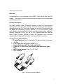
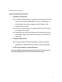
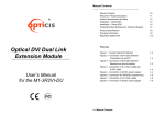
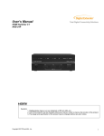
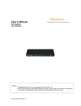
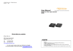
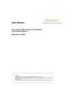
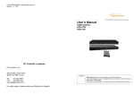
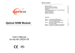
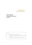
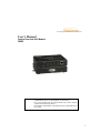
Total Digital Connectivity Solutions User’s Manual Optical Dual Link DVI Module OBDC Cautions: 1. Digitalextender logo is our own trademark of RTcomUSA.,Inc. 2. Any of the products may be changed without any notice in order to improve the function of the product. 3. The design and specification of the product may be changed without any prior notice. 1 TABLE OF CONTENTS 1- 1 WELCOME, PRODUCT DESCRIPTION............................................................................................. 3 1- 2 SYSTEM REQUIREMENTS FOR SETUP ........................................................................................... 4 1- 3 INSTALLATION....................................................................................................................................... 5 1- 4 INSTALLATION (CONTINUED)........................................................................................................... 6 1- 5 TROUBLESHOOTING............................................................................................................................ 6 1- 6 PRODUCT SPECIFICATIONS .............................................................................................................. 7 1- 7 WARRANTY INFORMATION ............................................................................................................... 8 1- 8 REGULATORY STATEMENTS ............................................................................................................. 9 2 1- 1 Welcome, Product Description Welcome! Congratulations on your purchase of the OBDC, Fiber Optical Dual Link DVI Module. This manual contains information that will assist you in installing and operating the product. Product Description The OBDC module offers 100 meters extension of dual link high-resolution digital graphic data over fiber, directly connected between PC and displays, supporting dual link DVI. Two boxes, located one by the PC and the other by the display are connected to each of them by a 1.0 m dual link DVI copper cable. Between two boxes, the 8 LC patch cord fiber bundled cable enables to transmit 7 channels (R, G, B, Clk, R2, G2, B2) of graphic data over it and the Digital Display Channel (DDC2B) interface are performed over a bundled copper cable, so called as DDC cable, which has RJ-45C connectors. Shipping Group of OBDC MOUDULE Tx and Rx boxes: One (1) Transmitter (Tx) Box and One (1) Receiver (Rx) Box. Two (2) dual link DVI copper cables: 1.0m Option: DDC cable (UTP for LAN) with RJ-45C. Option: 8 LC Patch Cord fiber bundled cable (Multimode glass fiber). AC/DC power adapter: One (1) +12V units User’s Manual Figure 1 – Overall Optical dual link DVI Module 3 1- 2 System Requirements for Setup System Requirements for Setup Hardware requirements You have a Media Receiver or a graphic controller card with a Dual link port in your Windows/Mac (Mac is option), or SUN system. It should support the maximum graphic resolution feature of the display to be connected. In case of using a computer, no special memory size, CPU speed and chipsets are required. Proper initial trial of the entire platform with its application using a short length copper cable is recommended prior to install with the optical link. Software requirements No special needs, if the Dual link graphic controller and display peripheral are operational with the platform’s OS and application. AC/DC Power Adapter Technical Advisory The power of OBDC is designed to supply to both modules of Tx and Rx over the DDC cable by plugging the power jack to either of their power plugs. 4 1- 3 Installation Installation Important: Please use the installation procedure below. Improper, or no operation may result if the start-up sequence is not correctly followed. Step 1 Carefully unpack the contents of the shipping group. Step 2 With system power turned off, connect the upstream Transmitter box to the DVI receptacle of PC by one dual link DVI copper cable in the shipping group. Figure 2 – Connection of DVI cable between Transmitter box and PC Step 3 In the same way as above, connect the Receiver box into the DVI receptacle of the display by the other dual link DVI copper cable. Figure 3 – Connection of DVI cable between Receiver box and the display Warning: Please DO NOT look directly into the LC receptacles of the Transmitter box, while it is powered on, although this product is regulated strictly enough to operate under the Laser Class I, classified by CDRH/FDA for eye safety. 5 1- 4 Installation (continued) Step 4 Remove the module dust covers and connect each duplex LC fiber cable one by one to each of 8 LC receptacles of the Transmitter and Receiver boxes, as shown in Fig. 4. Plug A to A and B to B. Carefully recheck polarities and ensure the duplex connectors are fully engaged. Step 5 Connect each RJ-45C of the DDC cable to each RJ-45C receptacle of the Transmitter and Receiver boxes. Figure 4 – Connection of 4 duplex LC fiber cables and a DDC cable Step 6 Connect an AC/DC power adapter to either of the Transmitter and Receiver boxes as your availability of AC outlets. 1- 5 Troubleshooting Figure 5 – Connection of AC/DC power adaptor Step 7 Power on the PC and display. Tip 1: After initial installation as guided in the above, we recommend you to power On and Off while all connections are set and the Tx/Rx boxes are powered in. Tip 2: Avoid “hot plugging” the Tx or Rx boxes as this is not recommended practice with live digital voltages. 6 1- 5 Troubleshooting Troubleshooting The display displays only black screen. • Check that all AC and DC plugs and jacks used by external power supplies (both RT Com and others) are firmly connected. • Ensure that power bars are live. • Ensure that the Tx and Rx boxes plug correctly to the PC and display, respectively. • Check if the PC and display are powered on and properly booted. • Re-boot up the system after reconnecting the optical system cable. Screen is distorted or displays noises.. • Reset the system. • Power down, disconnect the LC-LC fiber cable and try to blow inside of each LC receptacle by air blower • Reconnect the fiber cable and power up. • If noise continues, please contact the following. Maintenance No special maintenance is required for the optical system cables and power supplies. Ensure that the cables and power modules are stored or used in a benign environment free from liquid or dirt contamination. There are no user serviceable parts. Refer all service and repair issues to RT Com or its authorized distributor. 1- 6 Product Specifications Technical Support and Service For commercial or general product support, contact your reseller. For technical service, contact RT Com by email [email protected] or visit its website at www.digitalextender.com 7 1- 6 Product Specifications Product Specifications OBDC MOUDULE ( Optical Dual Link DVI Module) Fully backward compatible with DVI standard: supports DVI 1.0, using fiber-optic communication links and DDC2B. Extension limit: 100m (330feet) for 2,560x1,600 (1.65Gbps) in ultimate operation. Graphic Transmission Bandwidth: bandwidth per graphic channel. Fiber-optic Connection: The transmitter and receiver boxes of OBDC have 4 duplex LC receptacles connected to eight (8) 62.5/125μm or 50/125μm Multi-Mode glass fibers cables. Mechanical specifications of Tx and Rx boxes Dimensions: 108mm / 26mm / 80mm (W/H/D) Weight: 46.0 ± 1.5 gr for each of Tx and Rx. Environmental Specifications Operating temperature: -10°C to 50°C Storage temperature: - 30°C to 60°C supports up to 1.65Gbps AC/DC Power Adapter Power Input: Universal AC 85-264V, 50/60Hz, AC power cord with jack. 1-7 Warrantypower Information Power Output: +12 V, 3.0 A SMPS DC-power Adapter Cord DC Jack & length: Core is +12 V and outer cylinder is GND. Length is 18.5 cm AC Cord length: 1.8m Certification: PSE, UL, cUL, FCC, CE, TUV-GS 8 1- 7 Warranty Information Warranty Information 1 (One) Year Warranty RT Com warrants this optical dual link DVI module to be free from defects in workmanship and materials, under normal use and service, for a period of one (1) year from the date of purchase from RT Com or its authorized resellers. If a product does not work as warranted during the applicable warranty period, RT Com shall, at its option and expense, repair the defective product or part, deliver to customer an equivalent product or part to replace the defective item, or refund to customer the purchase price paid for the defective product. All products that are replaced will become the property of RT Com. Replacement products may be new or reconditioned. Any replaced or repaired product or part has a ninety (90) day warranty or the reminder of the initial warranty period, whichever is longer. RTcomUSA shall not be responsible for any software, firmware, information, or memory data of customer contained in, stored on, or integrated with any products returned to RT Com for repair under warranty or not. Warranty Limitation and Exclusion RTcomUSA shall have no further obligation under the foregoing limited warranty if the product has been damaged due to abuse, misuse, neglect, accident, unusual physical or electrical stress, unauthorized modifications, tampering, alterations, or service other than by RTcomUSA or its authorized agents, causes other than from ordinary use or failure to properly use the product in the 1-application 8 Regulatory Statements for which said product is intended. 9 1- 8 Regulatory Statements FCC/CE Statement for regulation of Electro-magnetic emission This device complies with part 15 of FCC Rules. Operation is subject to the following two conditions: (1) this device may not cause harmful interference, and (2) this device must accept any interference received, including interference that may cause undesired operation. This equipment has been tested and found to comply with the limits for a Class B digital device, pursuant to part 15 and 2 of FCC Rules, EN 55022/55024/61000-3 for CE certification. These limits are designed to provide reasonable protection against harmful interference when the equipment is operated in a residential installation. This equipment generates, uses, and can radiate radio frequency energy and. if not installed and used in accordance with the instruction guide, may cause harmful interference to radio communications. However, there is no guarantee that interference will not occur in a particular installation. If this equipment does cause harmful interference to radio or television reception, which can be determined by turning the equipment off and on, the user is encouraged to try to correct the interference by one or more of the following measures: • • • Re-orient or relocate the receiving antenna. Increase the separation between the equipment and the receiver. • Consult a service representative for help. Connect the equipment into an outlet on a circuit different from that to which the receiver is connected. Properly shielded and grounded cables and connectors must be used in order to comply with FCC/CE emission limits. Changes or modifications not expressly approved by the party responsible for compliance could void the user s authority to operate the equipment. Certification for Safety The AC/DC power adapter is certified by UL1310, 1950, 60950 for North America, cUL or CSA for Canada, TUV-CE & GS for EU and PSE for Japan. Certification of Eye Safety This laser product is inside implemented by using 850nm VCSEL (Vertical Cavity Surface Emitting Laser) Transceivers, manufactured by RT Com , which are all certified by CDRH/FDA referred in Accession Number 0210774 as classified in Laser Class 1. 10 RTcomUSA, Inc. Locations RTcomUSA 286 HOUSES CORNER RD. SPARTA, NJ 07871 Tel : 973-383-4878 www.digitalextender.com For order support, please contact your Distributor or Reseller. For technical support, [email protected] 11