1
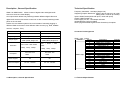
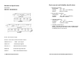
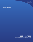
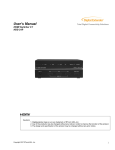
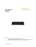
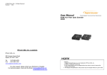
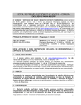
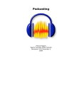
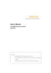
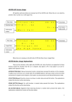
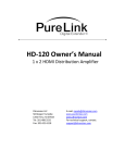
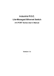
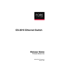
© 2006 RTcomUSA.,
Revision 1.5 1202
Ltd All Rights Reserved
Total Digital Connectivity Solutions
User’s Manual
HDMI Switcher
HDS-21R/
HDS-41R
RT ComUSA. Locations
RT ComUSA., Ltd.
286 Houses Corner Road
Sparta, NJ 07871 U.S.A.
Tel:
973-383-4878
Revision History
Fax:
973-383-1160
www.digitalextender.com
1. CONTENTS
For order support, please contact your Distributor or Reseller.
Cautions:
1. Digitalextender logo is our own trademark of RTcom USA.,Inc.
2. Any of the products may be changed without any notice in order to improve
the function of the product.
3. The design and specification of the product may be changed without any prior
Unpacking
Troubleshooting
Each HDMI Switch package includes the following items;
HDS-21R/41R HDMI LINK HDMI Switch Unit
5V Power Supply Adapter
User manual
Problem
Switch will not operate
Solution
Make sure the 5V power is plugged in the back of the unit.
Check to see if the power LED light is on.
No picture(or signal)
or Poor picture
1.In case your video source is HDCP enabled, make sure your
video display(HDTV) is HDCP compliant.
2.If you are using copper based HDMI cable, overall length of the
cables(length of the cables from video source to switch and
length of the cable from switch to display)should not exceed 20ft.
Exceeding 20ft. with copper based cables will result in no or poor
picture quality. To extend beyond 20ft, please use fiber optical
HDMI extension cables such as RT Com. Model OC cables.
3.Use high quality HDMI cables.
4.If you are using computers, try other refresh rate settings. Most
HDTVs have refresh rate of 48Hz and computer’s video cards
are usually set at higher refresh rate. Try lower refresh rates.
5.Makes sure all HDMI connectors are tightly secured to all
HDMI ports. Loose screws on the HDMI connectors will results in
no or poor picture.
6.Turn off all equipments(video source, switch and HDTV) and
restart all equipments.
Make sure the included batteries are correctly installed.
Make sure the 5V power is plugged in the back of the unit.
Check to see if the power LED light is on.
Try rebooting the switch by unplugging and re-plugging in the AC
plug of the 5V power adapter.
Our remote control units use unique codes. To program your own
universal remote control, make sure to use ”Learn” feature of
your universal remote control unit’s user manual.
Remote control unit will
not
operate
Programming Universal
Remote
Control
1-9 Troubleshooting
Warranty Information
CONTENTS
1 (One) Year Warranty
RT Com. warrants this HDMI Link HDMI Switch to be free from defects in
workmanship and materials, under normal use and service, for a period of
one (1) year from the date of purchase from RT Com or its authorized
resellers.
If a product does not work as warranted during the applicable warranty
period, RT Com shall, at its option and expense, repair the defective product
or part, deliver to customer an equivalent product or part to replace the
defective item, or refund to customer the purchase price paid for the defective
product.
Contents
1-1
Description, General Specification
1-2
Environmental and Reliability Specifications
1-3
Main Features
1-4
Replacement products may be new or reconditioned.
Video Connection
1-5
Any replaced or repaired product or part has a ninety (90) day warranty or the
reminder of the initial warranty period, whichever is longer.
Mechanical Specification
1-6
Technical Specification
1-7
Warranty Information
1-8
Troubleshooting
1-9
All products that are replaced will become the property of RT Com.
RT Com. shall not be responsible for any software, firmware, information, or
memory data of customer contained in, stored on, or integrated with any
products returned to RT Com for repair under warranty or not.
Warranty Limitation and Exclusion
RT Com. shall have no further obligation under the foregoing limited warranty
if the product has been damaged due to abuse, misuse, neglect, accident,
unusual physical or electrical stress, unauthorized modifications, tampering,
alterations, or service other than by RT Com or its authorized agents, causes
other than from ordinary use or failure to properly use the Product in the
application for which said Product is intended.
1-8 Warranty Information
1-1 Contents
Description , General Specification
Technical Specification
HDMI Link HDMI Switch allows number of digital video and digital audio
Frequency bandwidth: 1.65 Gbps (Single Link)
Supporting Graphic Resolution: UXGA (1600 X 1200 at up to 75Hz)
1080p (1920 X 1080 at up to 60Hz)
Inputs: HDMI Female (HDS-21R/ 2port , HDS-41R/ 4port)
Output: HDMI Female port
Power supply: DC 5V, 1.2A Adapter included.
Infrared Remote Control Included
HDCP (High-bandwidth Digital Content Protection) Compliant.
sources to share one video display.
Our unique switch allows easy switching between different digital video and
digital audio sources with remote control unit or with a manual switching button
place on the unit itself.
Perfect for home theater systems. No more hassles of manually plugging in
different HDMI connectors to view different video sources (e.g., DVD, Satellite
receiver, computer, TiVo).
ITEM
DESCRIPTION
DESCRIPTION
Model Name
HDS-21R
HDS-41R
Input Signal
HDMI Single Link , 2 Port
HDMI Single Link , 4 Port
Output Signal
HDMI (TMDS )Single Link
HDMI (TMDS )Single Link
Resolution
VGA / SVGA / XGA /UXGA
480i/p , 720i/p , 1080i/p
Receptacle
DC Power Jack
HDMI
VGA
/
SVGA
/
XGA
/UXGA
480i/p , 720i/p , 1080i/p
DC Power Jack
HDMI
HDCP Support
OK
OK
Power Consumption
DC +5V , 2W Max
DC +5V , 2W Max
Dimension
230x105x30 mm
330x105x30 mm
1-2 Description , General Specification
Connector Pin Assignment
HDMI Input , Output
Part No.
Pin No.
1
2
3
4
5
6
7
8
9
10
HDMI 19pin
11
12
13
14
15
16
17
18
19
1-7 Technical Specification
Description
TMDS DATA 2P
TMDS DATA 2 Shield
TMDS DATA 2M
TMDS DATA 1P
TMDS DATA 1 Shield
TMDS DATA 1M
TMDS DATA 0P
TMDS DATA 0 Shield
TMDS DATA 0M
TMDS Clock P
TMDS Clock Shield
TMDS Clock M
CEC
RESERVED
DDC Clock
DDC DATA
GND
+5v
Hot Plug Detect
Remarks
Mechanical Specification
Dimensions
HDS-21R : 230x105x30 mm
HDS-41R : 330x105x30 mm
Environmental and Reliability Specifications
1 Operating Conditions
Temperature : 10℃~ 40℃
Humidity
: 10% ~ 80%, non-condensing
Altitude
: maximum 3,000m
2 Transportation Conditions
Temperature
: -25℃~ 60℃
Humidity
: 5% ~ 95%, non-condensing
Altitude
: maximum 15,000m
3 Storage Conditions
Temperature
: -20℃~ 45℃
Humidity
: 5% ~ 95%, non-condensing
Altitude
: maximum 3,000m
4 Reliability Specifications
MTBF : more than 50,000 hours at 90% confidence level
Reliability specification and items : refer to “Specification
of reliability test for LCD monitor”
DC 5V : DC Power 5V Input
RS-232 : Com Port For Switch Function Control
HDMI IN CH1~4
HDMI OUT
: HDMI Input Signal
: HDMI Output Signals
LED CH1~4
: Selected Channel Indication
REMOTE
: IR Remote Signal Window
SELECT
: Each Channel Manual Select
1-6 Mechanical Specification
1-3 Environmental and Reliability Specifications
Main Features
High Quality Picture - No Signal Loss and Digital Noise Free
Our switchers are built to deliver the highest quality picture preserving the
native resolutions of the video sources without any signal loss. At the same
time, the digital noises that may affect the picture quality will be eliminated.
Due to the nature of the digital signals and passing through multiple stages of
connection when using switchers, it is important to eliminate the digital noises
and boost the signal strength to preserve/enhance the video signal quality.
Signal Amplification for signal reliability and long length signal
transmission. Our 5V power adapter supplies adequate power to amplify the
video signals from different video sources. This is necessary as the overall
length from the video source to the displays is longer when using the
switches(distance from the video source to the switch + distance from the
switch to the display). In most cases, the overall distance that the HDMI signal
will need to travel is over 10ft. Due to the nature of HDMI signals,
amplification is necessary to warrant the video quality and reliability. (Without
amplification, there may be occasional blackouts or blinking effects) With this
amplification feature, your video display can be extended up to 330ft using
our fiber optical HDMI cables.
Compact and Practical Design
Our switchers have all of the HDMI ports, power supply jack and RS232 port
in the back of the unit allowing it be mounted on any racks or with any other
components. In the front, there will be a remote control sensor, selector
switch, RS232 LED indicators and channel indicators.
Remote Control Unit with Discreet Channel selections
Remote Control Units with discreet channel selection feature is included in all
our switches. The channel buttons on the remote control unit will allow you to
change video sources easily and quickly.
RS232 Control
Our switches also feature RS232 Control. Our switches are capable of being
controlled by a remote computer. This is extremely helpful for many
applications where you need to automatically switch the video inputs.
Example: If you connect a PC to our switcher, you can program it to
automatically switch the sources. If you want to display input 1 for 1 hour and
then switch to input 2, you can do this with the PC. The RS232 LED indicators
in the front will allow you to check the communication between the PC and the
switch. Most other products require additional control box for this function.
1-4 Main Features
Video Connection
1. Connect your video source’s HDMI output port to the HDMI
switch’s HDMI input port using standard HDMI cables(not
included). Make sure all your HDMI sources and the display is
turned off before connecting the cables)
2. Connect your HDMI display’s HDMI input port to HDMI switch’s
HDMI output port. Make sure your HDMI display is turned off
before connecting the cables)
3. Plug the 5V power supply into the switch’s power input port.
4. Plug the 5V wall mount power supply into the wall outlet.
5. Turn on your display.
6. Turn on your video sources.
7. Use your remote control unit to switch channels. Or use the select
button on the front panel of the switch to change channels.
RS232 CONTROL CONNECTION
RS232 connection allows the user to interface the HDMI LINK switch with a
serial port on a computer or other control device. The computer or other
control device may require additional software for various control functions.
(Control software not included)
**RS232C Control Command with HDS-21R//41R Switcher
RS232C interface the HDS-21R/41R switcher with a serial port on a
control computer or other remote control devices.
Our HDS-21R and HDS-41R use pin#2 and #3 and the assignments are as follows;
Baud Rate : 9600bps
Control computer's RS232 pin# 2 is connected to our HDMI switcher's pin#3
Control computer's RS232 pin# 3 is connected to our HDMI switcher's pin#2
The control protocols are as follows;
Channel 1 request is ASCII code "@001*" and the response back to the computer is "!"
Channel 2 request is ASCII code "@002*" and the response back to the computer is "!"
Channel 3 request is ASCII code "@003*" and the response back to the computer is "!"
Channel 4 request is ASCII code "@004*" and the response back to the computer is "!"