1
User’s
Manual
EJX Series
HART Communication Type
IM 01C25T01-01E
IM 01C25T01-01E
Yokogawa Electric Corporation
3rd Edition
CONTENTS
CONTENTS
1.
INTRODUCTION .......................................................................................... 1-1
Regarding This Manual ................................................................................. 1-1
1.1 Safe Use of This Product .................................................................... 1-2
1.2 Warranty .............................................................................................. 1-2
1.3 ATEX Documentation .......................................................................... 1-3
1.4 Matching of Communicator DD and Instrument DD ........................... 1-4
2.
CONDITIONS OF COMMUNICATION LINE ............................................... 2-1
2.1
2.2
2.3
3.
Interconnection Between DPharp and the HART Communicator ...... 2-1
Communication Line Requirements .................................................... 2-1
Power Supply Voltage and Load Resistance ..................................... 2-1
OPERATION ................................................................................................ 3-1
3.1
Basic Operation of the 275 HART Communicator ............................. 3-1
3.1.1 Keys and Functions ...................................................................... 3-1
3.1.2 Display .......................................................................................... 3-2
3.1.3 Calling Up Menu Addresses ........................................................ 3-2
3.1.4 Entering, Setting, and Sending Data ........................................... 3-3
3.2 Parameter Usage and Selection ......................................................... 3-4
3.3 Menu Tree ........................................................................................... 3-5
3.4 Basic Setup ......................................................................................... 3-6
3.4.1 Tag and Device Information ......................................................... 3-6
3.4.2 Unit ............................................................................................... 3-6
3.4.3 Range Change ............................................................................. 3-7
(1) Keypad input ................................................................................ 3-7
(2) Apply values ................................................................................. 3-8
3.4.4 Output Mode ................................................................................. 3-9
3.4.5 Damping Time Constant Setup .................................................... 3-9
3.4.6 Output Signal Low Cut Mode Setup .......................................... 3-10
3.4.7 Impulse Line Connection Orientation Setup .............................. 3-10
3.5 Detailed Setup ................................................................................... 3-11
3.5.1 Bi-directional Flow Measurement ............................................... 3-11
3.5.2 Integral Indicator Display Mode ................................................. 3-11
3.5.3 Integral Indicator Scale Setup .................................................... 3-12
3.5.4 Unit for Displayed Temperature ................................................. 3-14
3.5.5 Unit for Displayed Static Pressure ............................................. 3-14
3.5.6 Test Output ................................................................................. 3-15
3.5.7 Sensor Trim ................................................................................ 3-16
(1) Zero Trim .................................................................................... 3-16
(2) Full Sensor Trim ......................................................................... 3-17
a. Auto Sensor Trim .................................................................... 3-17
b. Manual Sensor Trim ............................................................... 3-17
(3) Sensor Trim for Static Pressure ................................................. 3-18
(4) Reset Trim Adjustment to Factory Setting ................................. 3-18
3.5.8 Trim Analog Output .................................................................... 3-18
3.5.9 Burst Mode ................................................................................. 3-20
3.5.10 Multidrop Mode ........................................................................... 3-21
3.5.11 External Switch Mode ................................................................ 3-22
FD No. IM 01C25T01-01E
3rd Edition: Oct. 2004 (YK)
All Rights Reserved, Copyright © 2004, Yokogawa Electric Corporation
i
IM 01C25T01-01E
CONTENTS
3.5.12
3.5.13
(1)
(2)
(3)
(4)
3.5.14
3.5.15
3.5.16
3.5.17
4.
CPU Failure Burnout Direction and Hardware Write Protect .... 3-22
Software Write Protect ............................................................... 3-23
Setting Password ....................................................................... 3-23
Entering Password to Enable the Parameter Changes ............. 3-23
Releasing Password ................................................................... 3-23
Software Seal ............................................................................. 3-24
Signal Characterizer ................................................................... 3-24
Process Alarm ............................................................................ 3-25
Status Output (option code AL) ................................................. 3-26
Capillary Fill Fluid Density Compensation ................................. 3-27
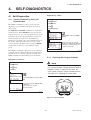
SELF-DIAGNOSTICS .................................................................................. 4-1
4.1
Self-Diagnostics .................................................................................. 4-1
4.1.1 Identify Problems by Using the Communicator ........................... 4-1
4.1.2 Checking with Integral Indicator ................................................... 4-1
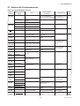
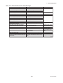
4.2 Alarms and Countermeasures ............................................................ 4-2
5.
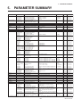
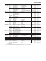
PARAMETER SUMMARY ........................................................................... 5-1
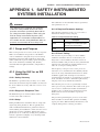
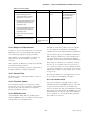
APPENDIX 1. SAFETY INSTRUMENTED SYSTEMS INSTALLATION .......... A-1
REVISION RECORD
ii
IM 01C25T01-01E
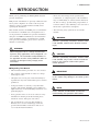
1. INTRODUCTION
1.
INTRODUCTION
Thank you for purchasing the DPharp EJX electronic
pressure transmitter.
• Please note that changes in the specifications,
construction, or component parts of the instrument
may not immediately be reflected in this manual at
the time of change, provided that postponement of
revisions will not cause difficulty to the user from a
functional or performance standpoint.
EJX pressure transmitters are precisely calibrated at the
factory before shipment. To ensure both safety and
efficiency, please read this manual carefully before
operating the instrument.
This manual describes the HART protocol communication functions of the EJX series and explains how to
set the parameters for EJX series pressure transmitters
using the 275 HART Communicator. For information
on the installation, wiring, and maintenance of EJX
series pressure transmitters, please refer to the user’s
manual of each model.
• The following safety symbols are used in this
manual:
WARNING
Indicates a potentially hazardous situation which,
if not avoided, could result in death or serious
injury.
WARNING
When using the EJX in a Safety Instrumented
Systems (SIS) application, refer to Appendix 1 in
this manual. The instructions and procedures in
the appendix must be strictly followed in order to
maintain the designed safety integrity of the
transmitter.
CAUTION
Indicates a potentially hazardous situation which,
if not avoided, may result in minor or moderate
injury. It may also be used to alert against
unsafe practices.
Regarding This Manual
• This manual should be provided on to the end user.
IMPORTANT
• The contents of this manual are subject to change
without prior notice.
Indicates that operating the hardware or software
in this manner may damage it or lead to system
failure.
• All rights reserved. No part of this manual may be
reproduced in any form without Yokogawa’s written
permission.
• Yokogawa makes no warranty of any kind with
regard to this manual, including, but not limited to,
implied warranty of merchantability and fitness for a
particular purpose.
NOTE
Draws attention to information essential for
understanding the operation and features.
• If any question arises or errors are found, or if any
information is missing from this manual, please
inform the nearest Yokogawa sales office.
• The specifications covered by this manual are
limited to those for the standard type under the
specified model number break-down and do not
cover custom-made instruments.
1-1
IM 01C25T01-01E
1. INTRODUCTION
(e) Modification
• Yokogawa will not be liable for malfunctions or
damage resulting from any modification made to this
instrument by the customer.
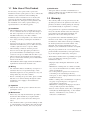
1.1 Safe Use of This Product
For the safety of the operator and to protect the
instrument and the system, please be sure to follow this
manual’s safety instructions when handling this
instrument. If these instructions are not heeded, the
protection provided by this instrument may be impaired. In this case, Yokogawa cannot guarantee that
the instrument can be safely operated. Please pay
special attention to the following points:
1.2 Warranty
• The warranty shall cover the period noted on the
quotation presented to the purchaser at the time of
purchase. Problems occurring during the warranty
period shall basically be repaired free of charge.
(a) Installation
• This instrument may only be installed by an engineer or technician who has an expert knowledge of
this device. Operators are not allowed to carry out
installation unless they meet this condition.
• With high process temperatures, care must be taken
not to burn yourself by touching the instrument or
its casing.
• Never loosen the process connector nuts when the
instrument is installed in a process. This can lead to
a sudden, explosive release of process fluids.
• When draining condensate from the pressure
detector section, take appropriate precautions to
prevent the inhalation of harmful vapors and the
contact of toxic process fluids with the skin or eyes.
• When removing the instrument from a hazardous
process, avoid contact with the process fluid and the
interior of the meter.
• All installation shall comply with local installation
requirements and the local electrical code.
• If any problems are experienced with this instrument, the customer should contact the Yokogawa
representative from which this instrument was
purchased or the nearest Yokogawa office.
• If a problem arises with this instrument, please
inform us of the nature of the problem and the
circumstances under which it developed, including
the model specification and serial number. Any
diagrams, data and other information you can
include in your communication will also be helpful.
• The party responsible for the cost of fixing the
problem shall be determined by Yokogawa following an investigation conducted by Yokogawa.
• The Purchaser shall bear the responsibility for repair
costs, even during the warranty period, if the
malfunction is due to:
- Improper and/or inadequate maintenance by the
purchaser.
- Malfunction or damage due to a failure to handle,
use, or store the instrument in accordance with the
design specifications.
- Use of the product in question in a location not
conforming to the standards specified by
Yokogawa, or due to improper maintenance of the
installation location.
- Failure or damage due to modification or repair by
any party except Yokogawa or an approved
representative of Yokogawa.
- Malfunction or damage from improper relocation
of the product in question after delivery.
- Reason of force majeure such as fires, earthquakes,
storms/floods, thunder/lightening, or other natural
disasters, or disturbances, riots, warfare, or
radioactive contamination.
(b) Wiring
• The instrument must be installed by an engineer or
technician who has an expert knowledge of this
instrument. Operators are not permitted to carry out
wiring unless they meet this condition.
• Before connecting the power cables, please confirm
that there is no current flowing through the cables
and that the power supply to the instrument is
switched off.
(c) Operation
• Wait 10 min. after the power is turned off before
opening the covers.
(d) Maintenance
• Please carry out only the maintenance procedures
described in this manual. If you require further
assistance, please contact the nearest Yokogawa
office.
• Care should be taken to prevent the build up of dust
or other materials on the display glass and the name
plate. To clean these surfaces, use a soft, dry cloth.
1-2
IM 01C25T01-01E
1. INTRODUCTION
1.3 ATEX Documentation
SF
This setion is only applicable to the countries in the
European Union.
Kaikkien ATEX Ex -tyyppisten tuotteiden käyttöhjeet
ovat saatavilla englannin-, saksan- ja ranskankielisinä.
Mikäli tarvitsette Ex -tyyppisten tuotteiden ohjeita
omalla paikallisella kielellännne, ottakaa yhteyttä
lähimpään Yokogawa-toimistoon tai -edustajaan.
GB
All instruction manuals for ATEX Ex related products
are available in English, German and French. Should
you require Ex related instructions in your local
language, you are to contact your nearest Yokogawa
office or representative.
P
Todos os manuais de instruções referentes aos produtos
Ex da ATEX estão disponíveis em Inglês, Alemão e
Francês. Se necessitar de instruções na sua língua
relacionadas com produtos Ex, deverá entrar em
contacto com a delegação mais próxima ou com um
representante da Yokogawa.
DK
Alle brugervejledninger for produkter relateret til
ATEX Ex er tilgængelige på engelsk, tysk og fransk.
Skulle De ønske yderligere oplysninger om håndtering
af Ex produkter på eget sprog, kan De rette
henvendelse herom til den nærmeste Yokogawa
afdeling eller forhandler.
F
Tous les manuels d’instruction des produits ATEX Ex
sont disponibles en langue anglaise, allemande et
française. Si vous nécessitez des instructions relatives
aux produits Ex dans votre langue, veuillez bien
contacter votre représentant Yokogawa le plus proche.
I
Tutti i manuali operativi di prodotti ATEX
contrassegnati con Ex sono disponibili in inglese,
tedesco e francese. Se si desidera ricevere i manuali
operativi di prodotti Ex in lingua locale, mettersi in
contatto con l’ufficio Yokogawa più vicino o con un
rappresentante.
D
Alle Betriebsanleitungen für ATEX Ex bezogene
Produkte stehen in den Sprachen Englisch, Deutsch
und Französisch zur Verfügung. Sollten Sie die
Betriebsanleitungen für Ex-Produkte in Ihrer
Landessprache benötigen, setzen Sie sich bitte mit
Ihrem örtlichen Yokogawa-Vertreter in Verbindung.
E
Todos los manuales de instrucciones para los productos
antiexplosivos de ATEX están disponibles en inglés,
alemán y francés. Si desea solicitar las instrucciones de
estos artículos antiexplosivos en su idioma local,
deberá ponerse en contacto con la oficina o el
representante de Yokogawa más cercano.
S
Alla instruktionsböcker för ATEX Ex (explosionssäkra)
produkter är tillgängliga på engelska, tyska och
franska. Om Ni behöver instruktioner för dessa
explosionssäkra produkter på annat språk, skall Ni
kontakta närmaste Yokogawakontor eller representant.
NL
Alle handleidingen voor producten die te maken
hebben met ATEX explosiebeveiliging (Ex) zijn
verkrijgbaar in het Engels, Duits en Frans. Neem,
indien u aanwijzingen op het gebied van
explosiebeveiliging nodig hebt in uw eigen taal, contact
op met de dichtstbijzijnde vestiging van Yokogawa of
met een vertegenwoordiger.
GR
ATEX Ex
, .
Ex Yokogawa .
1-3
IM 01C25T01-01E
1. INTRODUCTION
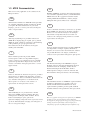
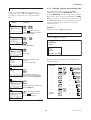
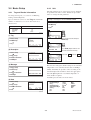
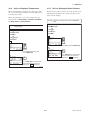
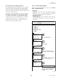
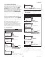
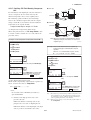
1.4
Matching of Communicator
DD and Instrument DD
CAUTION
Before using the 275 HART Communicator,
make that the device description(DD) installed in
the communicator matches that of the instrument
that is being set up. To check the DD of the
instrument and the HART communicator, follow
the steps below. If the correct DD is not installed
in the communicator, you must upgrade the DD
at an authorized facility. For communication tools
other than the 275 HART Communicator, contact
the vendor for upgrade information.
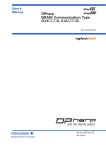
1. Checking the DD of the instrument
1) Connect the communicator to the instrument that is being set up.
2) Call Device setup and press [→] .
3) Call Review and press [→] .
4) Press [NEXT] or [PREV] to display Fld dev
rev to show the DD of the instrument.
[Example]
EJX:
Review
Fld dev rev
1
HELP
PREV
NEXT
EXIT
The instrument DD
version is 1.
F0101.EPS
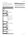
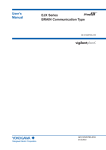
2. Checking the DD of the 275 HART Communicator
1) Turn on only the communicator.
2) Call Utility from the main menu and press
[→] .
3) Call Simulation and press [→] .
4) Select YOKOGAWA from the list of
manufacturers by pressing [ ↓ ] and press
[→] .
5) Select the model name of the
instrument(i.e. EJX) by pressing [ ↓ ] and
press [→] to show the DD of the communicator.
[Example]
HART Communicator
Fld dev rev
1 Dev v1, DD v1
Version 1.
The communicator DD
supports Version 1.
F0102.EPS
1-4
IM 01C25T01-01E
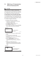
2. CONDITIONS OF COMMUNICATION LINE
2.
CONDITIONS OF COMMUNICATION
LINE
The HART communication signal is superimposed
onto the 4 to 20 mA DC analog signal. Since the
modulated wave is a communication signal, superimposing it on the normal signal will, from basic principles, cause no error in the DC component of the
analog signal. Thus, monitoring can be performed via
the 275 HART Communicator while the transmitter is
on-line.
2.2 Communication Line Requirements
Specifications for communication line:
Supply voltage (general use type): 16.6 to 42 V DC
Load resistance: 250 to 600 Ω (including cable
resistance)
Minimum cable size: 24 AWG, (0.51 mm diameter)
Cable type: single pair shielded or multiple pair with
overall shield
Maximum twisted-pair length: 10,000 ft (3,048 m)
Maximum multiple twisted-pair length: 5,000 ft
(1,524 m)
Use the following formula to determine cable length
for a specific application:
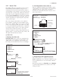
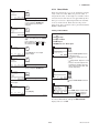
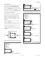
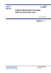
2.1 Interconnection Between
DPharp and the HART Communicator
The HART communicator can interface with the
transmitter from the control room, the transmitter site,
or any other wiring termination point in the loop,
provided there is a minimum of 250 Ω between the
connection and the power supply. To communicate, it
must be connected in parallel with the transmitter; the
connections are non-polarized. Figure 2.1 illustrates the
wiring connections for direct interface at the transmitter site for the DPharp. The HART communicator can
be used for remote access from any terminal strip as
well.
L=
Where: L = length in feet or meters
R = resistance in ohms, current sense
resistance plus barrier resistance
C = cable capacitance in pF/ft, or pF/m
Cf = maximum shunt capacitance of field
devices in pF
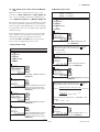
2.3 Power Supply Voltage and
Load Resistance
Control room
Relaying
terminals
65×106
(Cf+10,000)
–
C
(R×C)
Terminal
board
When configuring the loop, make sure that the external
load resistance is within the range in the figure below.
Distributor
(Note) With an intrinsically safe transmitter, external load resistance
includes safety barrier resistance.
DPharp
600
HART
communicator
PULSE
External
load
resistance
R (Ω)
SUPP
LY
CHECK
ALARM
HART communicator
R=
E–10.5
0.0244
Communication
applicable range
250
F0201.EPS
Figure 2.1 Connecting the HART Communicator
0
10.5
16.6
25.2
42
Power supply voltage E (V DC)
F0202.EPS
Figure 2.3 Relationship between Power Supply Voltage
and External Load Resistance
2-1
IM 01C25T01-01E
3. OPERATION
3.
OPERATION
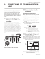
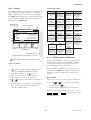
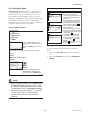
3.1 Basic Operation of the 275 HART Communicator
3.1.1
Keys and Functions
Communication cable
LCD (liquid crystal display)
(21 characters×8 lines)
Function keys
Functions of the keys are indicated on the
display.
Pressing
(HOME) when the display is
as shown changes the display to the Online
menu. (See 3.1.2 Display.)
EJX:
Process variables
1 Pres
0.000 kPa
2 Pres %
0.00 %
3 AO
4.000 mA
4 SP
0 MPa
5 Static Pres
0.0 %
HELP
SAVE
Moves the highlighting cursor on the display to
select the desired item.
HOME
Hot key
Calls up settings menu
1. Keypad input
2. Wrt protect menu
Power ON/OFF
1. Changes the display contents.
2. Moves the position where characters are
to be entered.
Pressing
calls up the display
corresponding to the highlighted item.
Pressing
returns to the previous display.
(See 3.1.3.)
Alphanumeric keys
1. Enters characters.
2. Selects the desired menu item with the
corresponding number. (See 3.1.4.)
Pressing a key enters a number.
Pressing a shift key and then an
alphanumeric key enters an
alphabetic character.
(Press)
(ENTER)
Shift keys
Use to enter alphabetic characters.
To enter 7,
7
To enter C,
C
F0301.EPS
Figure 3.1.1 HART Communicator
3-1
IM 01C25T01-01E
3. OPERATION
3.1.2
Display
Function Key Labels
The HART communicator searches for a transmitter on
the 4 to 20mA loop when it is turned on. When the
HART communicator is connected to the transmitter,
the Online menu (Top menu) is started automatically
and the following display appears. If no transmitter is
found, select the Online menu.
Manufacturer’s
transmitter type
<b>
<c>
<d>
Tag (8 characters)
<a>
EJX :YOKOGAWA
Online
1 Device setup
2 Pres
0.056 kPa
3 AO
4.009 mA
4 LRV
0.000 kPa
5 URV
100.000 kPa
<e>
SAVE
F1
F2
F3
F4
HELP
access on-line
help
ON/OFF
activates or
deactivates a
binary variable
ABORT
terminate
current task
OK
acknowledge
information on
screen
RETRY
try to reestablish
communication
DEL
delete current
character or Hot
Key Menu item
ESC
leave value
unchanged
ENTER
accept userentered data
EXIT
leave the
current menu
SEND
send data to
device, or mark
data to send
QUIT
terminate session
because of a
comunication
error
NEXT
leave the
current menu
YES
answer to
yes/no question
PGUP
move up one
help screen
PGDN
move down one
help screen
NO
answer to
yes/no question
ALL
include current
Hot Key item on
Hot Key Menu
for all devices
PREV
go to previous
message in a
list of messages
NEXT
go to next
message in the
list of messages
SKIP
do not mark
variable to be
sent in off-line
configuration
HOME
go to the top
menu in the
device
description
ONE
include Hot Key
item for one
device
EDIT
SAVE
save information edit a variable
value
to
communicator
SEND
ADD
send data to add current item
device, or mark
to Hot Key
data to send
Menu
Function keys
The highlighting cursor
BACK
go back to
menu from
which HOME
was pressed
F0303.EPS
Arrows appear when the SHIFT key is pressed.
3.1.3
Appears when the voltage level of the battery is low.
Subsection 3.3 Menu Tree shows the configuration of
all menu items available with the HART communicator. The desired item can be displayed with ease by
understanding the menu configuration.
F0302.EPS
Figure 3.1.2 Display
<a>
<b>
<c>
<d>
<e>
Calling Up Menu Addresses
When the HART communicator is connected to the
transmitter, the Online menu will be displayed after
the power is turned on. Call up the desired item as
follows:
appears and flashes during communication
between the HART communicator and the
transmitter. At Burst mode,
appears.
The item selected from the previous menu.
The available items in the menu of <b>.
or
appears when the item is scrolled out of
the display.
Function labels corresponding to specific function
keys are displayed. These labels indicate the
currently available choices.
Key operation
There are two choices to select the desired menu item.
1. Use the
or
and then press the
key to select the desired item,
key.
2. Press the number displayed for the desired item.
To return to the previous display, press the
key. If
,
and
are
displayed,
press
the
ABORT
ESC
EXIT
desired function key.
3-2
IM 01C25T01-01E
3. OPERATION
3.1.4
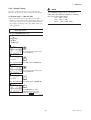
Example: Call up the Tag to change the tag number.
Data entered using the keys is set in the HART
communicator by pressing ENTER (F4). Then, by
pressing SEND (F2), the data is sent to the transmitter.
Note that the data is not set in the transmitter if SEND
(F2) is not pressed. As all the data that has been set in
the HART communicator is held in memory unless the
power is turned off, all the data can be sent to the
transmitter at once.
Check to see where Tag is located in the menu
configuration. Then, call up the Tag on the display
according to the menu tree (See section 3.3 Menu
Tree).
Display
Operation
1
EJX:YOKOGAWA
Online
1 Device setup
2 Pres
3 AO
4 LRV
5 URV
DEL
SET
ESC
Entering, Setting, and Sending Data
or
Operation
Entering data on the Tag setting display.
ENTER
Display 1 appears when the
HART Communicator is turned on.
Select Device setup.
Example: To change from Tag YOKOGAWA to FI1-1A.
2
EJX:YOKOGAWA
Device setup
1 Process Varlables
2 Diag/Service
3 Basic Setup
4 Detailed Setup
5 Review
DEL
SAVE HOME ENTER
Call up the Tag setting display.
×2
1. Device setup
or
3. Basic setup
1. Tag
Select Basic setup.
3
EJX:YOKOGAWA
Basic Setup
1 Tag
YOKOGAWA
2 Unit
kPa
3 Re-range
4 Device information
5 Xfer fnctn
Linear
DEL
SAVE HOME ENTER
HELP
EJX:YOKOGAWA
Tag
YOKOGAWA
YOKOGAWA
HELP
Select Tag.
DEL
ESC
ENTER
F0305.EPS
4
EJX:YOKOGAWA
Tag
YOKOGAWA
YOKOGAWA
When the setting display shown above appears, enter
the data as follows:
The display for the Tag setting
appears.
See 3.1.4 for data entry.
DEL
HELP
DEL
ESC
Character to
be entered
ENTER
5
EJX:YOKOGAWA
Tag
YOKOGAWA
FI1-1A
HELP
DEL
(ENTER)
ESC
ENTER
After entering the data, set the
HART communicator with the data
entered by pressing ENTER (F4).
Operation
Display
F
F O K O G A W A
I
F I K O G A W A
1
F I 1 O G A W A
-
F I 1 - G A W A
1
F I 1 - 1 A W A
A
F I 1 - 1 A W A
6
EJX:YOKOGAWA
Basic setup
1 Tag
2 Unit
3 Re-range
4 Device information
5 Xfer fncth
HELP SEND HOME ENTER
(SEND)
Send the data to the transmitter by
pressing SEND (F2).
7
EJX:FI1-1A
Basic Setup
1 Tag
2 Unit
3 Re-range
4 Device information
5 Xfer fncth
HELP SAVE HOME ENTER
*
flashes during communication.
When SEND disappears, the
transmission is complete.
Deletes
characters.
F I 1 - 1 A
(DEL)
F0306.EPS
F0304.EPS
3-3
IM 01C25T01-01E
3. OPERATION
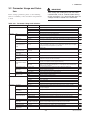
3.2 Parameter Usage and Selection
IMPORTANT
After setting and sending data with the HART
communicator, wait 30 seconds before turning
off the transmitter. If it is turned off too soon, the
settings will not be stored in the transmitter.
Before setting a parameter, please see the following
table for a summary of how and when each parameter
is used.
Table 3.2.1 Parameter Usage and Selection
Item
Memory
Transmitter
HART communicator
Tag number, up to 8 characters
Descriptor
Up to 16 characters
Message
Up to 32 characters
xx/yy/zz
Unit
Sets a pressure unit for the measured pressure
P. 3-6
Range
LRV/URV
Sets the calibration range by the keypad
P. 3-7
Apply values
Range for 4 to 20 mA DC signal is set with actual input applied
P. 3-8
Output mode
Xfer fnctn
Sets mode for output signal to “linear mode” (proportional to input differential pressure)
or to “Square root mode” (proportional to flow)
P. 3-9
Damping time constant
Pres Damp
Adjust the output response speed for the input pressure of differential pressure
Output signal low cut
mode
Low Cut
Used mainly to stabilize output near 0 if output signal is the square root mode. Two
modes are available: forcing output to 0% for input below a specific value, or changing
to proportional output for input below a specific value
Low cut mode
Linear or Zero
Bi-dir mode
Used to measure bi-directional flows
P. 3-10
P. 3-11
Temp Unit
Sets a temperature unit displayed on HART communicator
Unit for displayed static
pressure
SP Unit
Sets a pressure unit for the static pressure displayed on HART communicator
Impulse line connection
orientation
H/L Swap
Used where installation conditions make it imperative to connect high pressure side
impulse line to low pressure side of transmitter
P. 3-10
Disp Pres % fnctn
Sets mode for integral indicator to “linear mode” (proportional to input differential
pressure) or to “Square root mode” (proportional to flow)
P. 3-11
Disp select
Sets the following 5 types of integral indicator scale ranges and unit: input pressure, % of
P. 3-12
range, user set scale, input static pressure, % of static pressure range, and alternating
among any four of the above
Engr disp range
Sets Engr Unit/Modify Engr Unit/Engr LRV/Engr URV/Engr point/Engr exp
Burst option
Selection of the data to be sent continuously (PV, % range/current, or Process vars/crnt)
Burst mode
ON/OFF switching of burst mode
Process Alerts
Used for alarm generation on the integral indicator
Poll addr
Sets the polling address (1 to 15)
Polling
ON/OFF switching of multidrop mode
Pres and Pres %
Pressure variable and % output variable
AO
4 to 20 mA output variable
Snsr temp
Sensor temperature
SP and SP %
Static pressure variable and % static pressure variable
P. 3-14
Integral indicator display
mode
Integral indicator scale
Burst mode
Process alarm
Multidrop mode
Monitoring
P. 3-13
P. 3-20
P. 3-25
P. 3-21
—
Engr Disp/exp/Unit
Displays the output of user setting engineering information
Loop test
Used for loop checks. Output can be set freely from –2.5% to 110% in 1% steps
P. 3-15
Self-diagnostics
Self test and Status
Check using the self-test and status command. If an error is detected, the corresponding
message is displayed
P. 4-1
Output when CPU error
has occurred
AO Alm typ
Display the status of 4 to 20 mA DC output when a failure occurs
External volume switch
Ext SW
Display/set the external volume protect/permit for LRV (URV) setting
Write protect
Displays the permit/protect status of setting changes depending on communications
Enable wrt 10min
Write protect status is released for 10 minutes when the password is entered
New password
Sets a new password
Zeroing
Zero trim
Sets the current input value to 0 kPa
Sensor trim
Pres and SP sensor trim
Adjust the measured differential pressure and static pressure variables
Analog output trim
D/A trim, Scaled D/A trim
Adjust the output value at the points of 4 mA and 20 mA
P. 3-18
Signal characterizer
S.C. menu
Used for compensate the output for the non-linear application
P. 3-24
Capillary fill fluid density
compensation
T.Z. Cmp mode
Compensates the zero shift by the ambient temperature effect on the capillary tubes.
Test output
Software write protect
Adjustment
P. 3-6
Date
Display
Maintenance
Page
Unit
Bi-directional flow
measurement mode
Unit for displayed
temperature
HART output
Description
Tag
P. 3-22
P. 3-23
P. 3-16
P. 3-27
T0301.EPS
3-4
IM 01C25T01-01E
3. OPERATION
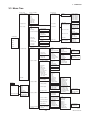
3.3 Menu Tree
(Device setup)
1 Process variables
(Diag/Service)
(Process variables)
1
2
3
4
5
6
7
8
9
Pres
Pres %
AO
SP
SP %
Snsr temp
Engr Disp
Engr exp
Engr Unit
1 Test device
1 Status
2 Self test
2 Loop test
1 Re-range
2 Diag/Service
2 Analog output trim
(Basic setup)
3 Basic setup
1 Tag
2 Unit
3 Re-range
4 Device information
Online Menu
5 Xfer fnctn
1 Device setup
3 Calibration
1 Keypad input
2 Apply values
1
2
3
4
4 Error log
2 Pres
7 Low cut
3 AO
8 Low cut mode
Linear
Zero
4 LRV
9 H/L Swap
SP setup
Normal
Reverse
5 URV
1 Sensors
1 Pressure sensor
2 SP sensor
3 Temp sensor
1 Snsr temp
2 Amp temp
3 Temp Unit
1
2
3
4
Pres
Pres %
Unit
Pres sensor trim
1
2
3
4
5
6
SP
SP %
SP Unit
A/G Select
SP H/L Select
SP sensor trim
7 SP setup
2 Signal condition
1 Process variables
2
3
4
5
6
7
8
9
Re-range
Unit
Xfer fnctn
Pres Damp
Low cut
Low cut mode
H/L Swap
Bi-dir mode
Quick resp
T.Z. Cmp menu
S.C. menu
1 S.C.
2 Num of points
3 Point setting
5. Review
3 Output condition
Hot Key
2 Wrt protect menu
1 D/A trim
2 Scaled D/A trim
3 Clear D/A trim
4 SP sensor trim
1
2
3
4
Static pres trim
SP LTP
SP UTP
SP trim info.
5 Trim info.
1
2
3
4
Trim Who
Trim Date
Trim Loc
Trim Desc
1 Error log view
2 Error log Clear
(Detailed setup)
4 Detailed setup
1 Keypad Input
1 Keypad input
2 Apply values
Press zero trim
Press trim
P LTP
P UTP
Pres trim info.
1 Linear
2 Sq root
6 Pres Damp
Status group 1
Status group 2
Status group 3
Status group 4
Status group 5
Status group 6
Status group 7
1
2
3
4
5
3 Pres sensor trim
Date
Descriptor
Message
Write Protect
1
2
3
4
5
6
7
1 Process variables
1
2
3
4
Pres
Pres %
SP
Snsr temp
LRV
URV
Unit
LSL
USL
Min Span
1
2
3
4
Write protect
Enable wrt 10min
New password
Software seal
3 HART output
1 Disp select
2 P disp condition
3 SP disp condition
4 Engr disp range
5 Bar indicator
5 Device information
6 Test Key
1 Field device info
2 Sensor information
3 Self test
1 P LTD
2 P UTD
3 Clear P snsr trim
1
2
3
4
Static Pres trim
SP LTP
SP UTP
SP trim info.
1 SP LTD
2 SP UTD
3 Clear SP snsr trim
1
2
3
4
5
SP range
SP Unit
SP Damp
SP A/G Setup
SP H/L Select
1
2
3
4
5
6
7
8
Loop test
D/A trim
Scaled D/A trim
Clear D/A trim
AO alm typ
Auto recover
AO lower limit
AO upper limit
1
2
3
4
5
6
7
Pres Alert mode
Config Pres Alerts
SP Alart mode
Config SP Alerts
Temp Alert mode
Config Temp Alerts
DO Config
1
2
3
4
5
6
7
8
9
Tag
Date
Descriptor
Message
Model 1
Model 2
Model 3
Write Protect
Ext SW
Revision #s
Additional Info
1 T.Z. Cmp mode
2 Temp Zero
1
2
3
4
5
6
7
8
9
Pres
Pres %
AO
SP
SP %
Snsr temp
Engr Disp
Engr exp
Engr Unit
Digital Output
1
2
3
4
Poll addr
Num req preams
Burst mode
Burst option
1
2
3
4
Disp Out 1
Disp Out 2
Disp Out 3
Disp Out 4
4 Process Alerts
4 Display condition
Pres Zero trim
Pres trim
P LTP
P UTP
Pres trim info.
1 Keypad input
2 Apply values
2 Analog output
1
2
3
4
5
6
1
2
3
4
5
1 Disp Pres % fnctn
2 Disp Pres % Reso
3 Pres disp point
1
2
3
4
5
6
7
Engr LRV
Engr URV
Engr exp
Engr Unit
Engr point
Set Engr Unit
Modify Engr Unit
1
2
3
4
Digital Output
DO Select
DO Signal type
DO Test
1 Universal rev
2 Fld dev rev
3 Software rev
F0307.EPS
3-5
IM 01C25T01-01E
3. OPERATION
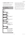
3.4 Basic Setup
3.4.2
3.4.1
The unit parameter is set at the factory before shipment
if specified at the time of order. Follow the procedure
below to change the unit parameter.
Tag and Device Information
To change the Tag No., see section 3.1.4 Entering,
Setting, and Sending Data.
Unit
Example: To change the unit from mmH2O to inH2O
Up to 8 characters can be set with Tag. The maximum
number of characters to be set for other items is as
shown below.
1. Device setup
3. Basic setup
Item
Number of characters
Tag
Descriptor
Message
Date
8
16
32
2/2/2
2. Unit
1
EJX:YOKOGAWA
Unit
mmH2O
MPa
inH2O
mmH2O
ftH2O
DEL
SAVE
HELP
T0302.EPS
(1) Tag
1. Device setup
3. Basic setup
DEL
ESC
EJX:YOKOGAWA
Basic setup
1 Tag
YOKOGAWA
2 Unit
mmH2O
3 Re-range
4 Device infomation
5 Xfer fnctn
Linear
DEL
HELP
SEND HOME ENTER
ENTER
(2) Descriptor
1. Device setup
EJX:YOKOGAWA
Descriptor
EJX:YOKOGAWA
Basic setup
1 Tag
YOKOGAWA
2 Unit
mmH2O
3 Re-range
4 Device infomation
5 Xfer fnctn
Linear
DEL
HELP
SAVE HOME ENTER
4. Device information
DEL
(ENTER)
(SEND)
Press SEND (F2) to send the new
unit to the transmitter memory.
3
3. Basic setup
HELP
ENTER
2
1. Tag
HELP
ESC
Select the desired unit and press
ENTER (F4).
EJX:YOKOGAWA
Tag
YOKOGAWA
YOKOGAWA
ESC
ENTER
2. Descriptor
Check that
SEND
becomes
SAVE
.
F0309.EPS
(3) Message
1. Device setup
Note that the Yokogawa default setting for the standard
temperature is 4C (39.2F). For the units of mmH2O,
inH2O, and ftH2O, the pressure varies according to the
standard temperature definition. Select the appropriate
unit with @68degF when a standard temperature of
20C (68F) is required.
EJX:YOKOGAWA
Message
3. Basic setup
4. Device information
HELP
DEL
ESC
ENTER
3. Message
Available pressure units are shown below.
(4) Date
1. Device setup
3. Basic setup
EJX:YOKOGAWA
Date
**/**/**
**/**/**
inH2O@68degF
inHg
ftH2O@68degF
mmH2O@68degF
mmHg
psi
bar
4. Device information
HELP
ESC
ENTER
4. Date
F0308.EPS
mbar
g/cm2
kg/cm2
Pa
kPa
torr
atm
MPa
inH2O
mmH2O
ftH2O
hPa
FX0301.EPS
3-6
IM 01C25T01-01E
3. OPERATION
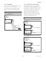
3.4.3
Range Change
NOTE
The range values are factory-set as specified by the
customer. To change the range, follow the steps below.
The calibration range can be set as LRV URV under the following conditions, reversing
the 4 to 20 mA output signal.
LSL LRV USL
LSL URV USL
|URV LRV| Min. Span
(1) Keypad input — LRV and URV
• The measurement span is determined by the upper
and lower range values. In this method, the upper and
lower range values can be set independently, and the
span changes according to the range limit values sent
to the transmitter.
Example: To change the range from 0 to 2500 mmH2O to
500 to 3500 mmH2O
Call up the Keypad input display.
1. Device setup
3. Basic setup
3. Re-range
1. Keypad input
1
EJX:YOKOGAWA
Keypad input
1 LRV
0.0
2 URV
2500.0
3 Unit
4 LSL
-10197.2
5 USL
10197.2
HELP SAVE HOME
mmH2O
mmH2O
mmH2O
mmH2O
mmH2O
ENTER
To change the Lower Range Value,
select the LRV item.
2
‘5 0 0’
EJX:YOKOGAWA
LRV
0.0 mmH2O
0.0
(ENTER)
HELP
DEL
ESC
ENTER
Enter 500, and press ENTER (F4).
3
EJX:YOKOGAWA
Keypad input
1 LRV
500.0
2 URV
2500.0
3 Unit
4 LSL
-10197.2
5 USL
10197.2
DEL
HELP
SEND HOME
mmH2O
mmH2O
mmH2O
mmH2O
mmH2O
ENTER
To change the Upper Range Value,
select the URV item.
4
‘3 5 0 0’
EJX:YOKOGAWA
URV
2500.0 mmH2O
2500.0
(ENTER)
HELP
DEL
ESC
ENTER
Enter 3500, and press ENTER (F4).
5
EJX:YOKOGAWA
Keypad input
1 LRV
500.0
2 URV
3500.0
3 Unit
4 LSL
-10197.2
5 USL
10197.2
HELP SEND HOME
mmH2O
mmH2O
mmH2O
mmH2O
mmH2O
ENTER
(SEND)
Press SEND (F2) to send the
changed data to the transmitter.
Check that SEND disappears.
F0310.EPS
3-7
IM 01C25T01-01E
3. OPERATION
(2) Apply values — changing the ranges while
applying an actual Input
• The measurement span is determined by the upper
and lower range values. Changing the lower range
value causes the upper range value to change
automatically, keeping the span constant. If a change
in the lower range value causes the upper range value
to exceed the measuring limit of the transmitter, an
error message appears and the transmitter holds the
output signal right before the error occurred. Enter
the correct values within the range of the sensor
limits.
• Note that changing the upper range value does not
cause the lower range value to change. Thus, changing the upper range value also changes the span.
• This feature allows the lower and upper range values
to be setup automatically with the actual input
applied. If the upper and lower range values are set,
URV and LRV are changed at the same time.
Example: To change the range from 0 to 2500 mmH2O to
500 to 3000 mmH2O
Call up the Apply values display.
1. Device setup
3. Basic setup
3. Re-range
2. Apply values
1
EJX:YOKOGAWA
WARN-Loop should be
removed from
automatic control
DEL
SET
ABORT
(OK)
OK
Press OK (F4).
2
EJX:YOKOGAWA
Set the:
1 4mA
2 20mA
3 Exit
HELP
SAVE
(ENTER)
ABORT ENTER
To set the lower range value, select
4mA and press ENTER (F4).
3
EJX:YOKOGAWA
Apply new 4ma input
(OK)
HELP
DEL
ABORT
OK
Apply the pressure of 500mmH2O.
After obtaining a stable pressure,
press OK (F4).
4
EJX:YOKOGAWA
Current applied
process value: 500.01
mmH2O
1 Set as 4mA value
2 Read new value
3 Leave as found
DEL
HELP
SEND ABORT ENTER
(ENTER)
The LRV to be changed is 500.01
mmH2O.
• Selecting item 1 sets LRV to
500.01 mmH2O.
• Selecting item 2 reads LRV again.
To set LRV = 500.01, select item 1
and press ENTER (F4).
5
EJX:YOKOGAWA
Set the
1 4mA
2 20mA
3 Exit
HELP
DEL
×2
ABORT ENTER
(ENTER)
Select Exit and press ENTER (F4).
Check the value after completing
the range change with URV and
LRV.
* The span is maintained the same
as when changing LRV with Apply
values. In this case, if LRV is
changed from 0 to 500, URV is
changed automatically to 3000.
F0311.EPS
3-8
IM 01C25T01-01E
3. OPERATION
3.4.4
Output Mode
3.4.5
The mode setting for the output signal and the integral
indicator can be performed independently.
Damping Time Constant Setup
The damping time constant is set as specified in the
order when the instrument is shipped. Follow the
procedure below to change the damping time constant.
The damping time constant for the amplifier assembly
can be set here. The damping time constant for the
entire transmitter is the sum of the values for the
amplifier assembly and the capsule assembly.
The output mode for the output signal is set as specified in the order when the instrument is shipped.
Follow the procedure below to change the mode.
Example: To change the mode from Linear to Sq root.
Any number from 0.00 to 100.00 can be set for the
damping time constant. Note that setting the quick
response parameter ON enables you to set the time
constant between 0.00 and 0.49 seconds.
Call up the Xfer fnctn display.
1. Device setup
3. Basic setup
5. Xfer fnctn
Example: To change from 2.0 seconds to 0.5 seconds
1
Call up the Pres Damp display.
EJX:YOKOGAWA
Xfer function
Linear
Linear
Sq root
DEL
SET
1. Device setup
ESC
ENTER
3. Basic setup
(ENTER)
6. Pres Damp
1
(SEND)
‘0 . 5’
EJX:YOKOGAWA
Pres Damp
2.00 sec
0.5
[1] Select Sq root, and press
ENTER (F4).
[2] Press SEND (F2) to send the
data to the transmitter, then
check to confirm that SEND
disappears.
(ENTER)
HELP
DEL
ESC
ENTER
Enter 0.5 and press ENTER (F4).
2
EJX:YOKOGAWA
Basic Setup
3 Re-range
4 Device information
5 Xfer fncfn
6 Pres Damp
0.50 sec
7 Low cut
10.00 %
HELP
SEND
HOME ENTER
F0312.EPS
Press SEND (F2) to send the data
to the transmitter.
Call up the Quick resp display to set the value to less
than 0.5 seconds.
1. Device setup
4. Detailed setup
2. Signal condition
Quick resp
1
EJX:YOKOGAWA
Quick resp
Off
Off
On
(ENTER)
HELP
DEL
ESC
ENTER
Select On and press ENTER (F4).
2
EJX:YOKOGAWA
Signal condition
7 Low cut mode
8 H/L Swap
Normal
9 Bi-dir mode
Off
Quick resp
On
T.Z. Cmp menu
HELP
SEND
HOME ENTER
Press SEND (F2) to send the data
to the transmitter.
F0313.EPS
3-9
IM 01C25T01-01E
3. OPERATION
3.4.6
Output Signal Low Cut Mode Setup
3.4.7 Impulse Line Connection Orientation
Setup
Low cut mode can be used to stabilize the output
signal near the zero point.
This function reverses the impulse line orientation.
Follow the procedure below to make this change.
The low cut point can be set in a range from 0 to 20%,
the direct ratio corresponding to the output signal of 4
to 20 mA. (Hysteresis: ±10% of the cut point)
Example: Assign the high pressure impulse line connection
to the L side of the transmitter.
Either LINEAR or ZERO can be selected as the low
cut mode. Unless otherwise specified, the cut mode is
set to LINEAR at the factory.
1. Device setup
3. Basic setup
Note that when the output modes of the output signal
and the display are selected as Sq root and Linear
accordingly, the low cut function is not available for
the display value.
9. H/L Swap
1
EJX:YOKOGAWA
H/L Swap
Normal
Normal
Reverse
HELP
Example: To set the low cut range to 20% and the cut mode
to ZERO in the Sq root output mode, proceed as
follows:
EJX:YOKOGAWA
Basic setup
5 Xfer fnctn
Linear
6 Pres Damp
0.50 sec
7 Low cut
20.00 %
8 Low cut mode
Zero
9 H/L Swap
Reverse
HELP SEND HOME
Output
0
50
(%)
Input
For low cut in linear mode
ENTER
(ENTER)
2
20
20
ESC
Call up the H/L Swap Display
Select Reverse, and press ENTER
(F4).
(%)
50
Output
(%)
50
SEND
0
Input
50
(%)
(SEND)
Press SEND (F2) to send the data
to the transmitter, then check to
confirm that SEND disappears.
F0316.EPS
For low cut in zero mode
F0314.EPS
Figure 3.4.6 Low Cut Mode
1. Device setup
3. Basic setup
7. Low Cut and 8. Low cut mode
1
‘2 0’
EJX:YOKOGAWA
Low cut
10.00 %
10.00
(ENTER)
HELP
DEL
ESC
ENTER
Call up Low cut, and set to 20%.
ESC
ENTER
(ENTER)
2
EJX:YOKOGAWA
Low cut mode
Linear
Linear
Zero
HELP
SEND
3
EJX:YOKOGAWA
Basic Setup
4 Device information
5 Xfer fnctn
Linear
6 Pres Damp
0.50 sec
7 Low cut
20.00 %
8 Low cut mode
Zero
HELP SEND HOME
OK
Select the Low cut mode, and set
to Zero.
(SEND)
Press SEND (F2) to send the date,
then check to confirm that SEND
disappears.
F0315.EPS
3-10
IM 01C25T01-01E
3. OPERATION
3.5 Detailed Setup
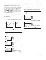
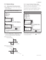
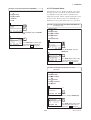
3.5.2
3.5.1
The mode setting for the output signal and the integral
indicator can be performed independently.
Bi-directional Flow Measurement
(a) Bi-dir mode enables selection of 50% output at an
input of 0 mmH2O.
Integral Indicator Display Mode
The output mode for the integral indicator is set as
specified in the order when the instrument is shipped.
Follow the procedure below to change the mode.
Example: If measurement range is 0 to 3000mmH2O
(LRV = 0 mmH2O, URV = 3000 mmH2O)
Example: Change from Linear to Sq root.
1. Device setup
4. Detailed setup
1. Device setup
2. Signal condition
4. Detailed setup
9. Bi-dir mode
4. Display condition
1
2. P disp condition
EJX:YOKOGAWA
Bi-dir mode
Off
off
on
HELP
SEND
1. Disp Pres % fnctn
1
ESC
ENTER
EJX:YOKOGAWA
Disp Pres % fnctn
Linear
Linear
Sq root
(ENTER)
Call up the Bi-dir mode display
Select on, and press ENTER (F4).
HELP
2
EJX:YOKOGAWA
Signal condition
5 Pres Damp
0.50 sec
6 Low cut
20.00 %
7 Low cut mode
Zero
8 H/L swap
Reverse
9 Bi-dir mode
On
HELP SEND HOME
(SEND)
SEND
ESC
ENTER
Call up the Disp Pres % fnctn
Display. Select Sq root, and press
ENTER (F4).
2
EJX:YOKOGAWA
P disp condition
1 Disp Pres % fnctn
2 Disp Pres % Reso
3 Pres disp point
Press SEND (F2) to send the data
to the transmitter, then check to
confirm that SEND disappears.
Note: The measurement range changes to 3000 to 0 to
3000 mmH2O, corresponding the output of 0% to 50%
to 100%. Note that LRV and URV values are not
changed.
HELP
(ENTER)
SEND
HOME
2
(SEND)
Press SEND (F2) to send the data
to the transmitter, then check to
confirm that SEND disappears.
F0319.EPS
F0317.EPS
If the instrument is equipped with an integral indicator
and the transfer function is sq root, “
” is displayed
on the integral indicator.
(b) Combining Bi-dir mode with Xfer fnctn provides
a square root output computed independently for
0% to 50% output and for 50% to 100% output.
Output mode “LINEAR”
20 mA (100% display)
LRV
HRV
4 mA (–100% display)
Output mode “SQUARE ROOT”
20 mA (100% display)
Low Cut
LRV
HRV
4 mA (–100% display)
F0318.EPS
3-11
IM 01C25T01-01E
3. OPERATION
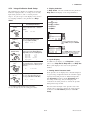
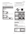
3.5.3
a. Display Selection
At Disp select, select the variable that the parameter
Disp Out 1 will display on the integral indicator.
Integral Indicator Scale Setup
The following five displays are available for integral
indicators: input pressure, % of range, user set scale,
input static pressure*1, and % of static pressure
range*1. A cycle of up to four displays can be shown
by assigning variables to the parameters at Disp
select.
Example: Change from PRES % to PRES for the display.
1. Device setup
4. Detailed setup
Available displays
Input pressure
(PRES)
Description
and related parameters
Indicates values of input pressure
with the indication limits 99999 to
99999.
PRES
% of range
(PRES %)
4. Display condition
1. Disp select
1. Disp Out 1
456 kPa
1
EJX:YOKOGAWA
Disp Out 1
PRES %
PRES %
ENGR. PRES
SP
SP %
HELP SEND
Indicates input pressure in 2.5 to
110% range depending on the
set range (LRV and URV).
PRES %
ESC
ENTER
Call up the Disp Out 1 display.
Select PRES, and press ENTER
(F4).
45.6 %
2
User set scale
(ENGR. PRES)
Engr
Engr
Engr
Engr
Engr
Input static pressure
(SP)*1
LRV
URV
exp
Unit
point
HELP
0.0
45.0
!100
m3/min
1
HOME
(SEND)
Press SEND (F2) to send the data
to the transmitter, then check to
confirm that SEND disappears.
b. Cyclic Display
In addition to the display set at Disp Out 1, displays
can be set at Disp Out 2, Disp Out 3, and Disp Out
4 for cyclic display in the order of the parameter
number.
4.000 MPa
c. Setting Static Pressure Scale
Static pressure can be displayed as a measured input or
as a percentage, independent from the 4-20 mA output
signal for measured pressure or differential pressure.
The SP setup parameters under SP sensor allow
the setting of the range, unit, and damping time
constant for the static pressure as well as the pressure
management range for PV.
Indicates input static pressure in –10
to 110% range depending on the
set range (SP LRV and SP URV).
SP %
SEND
PRES
Not Used
Not Used
Not Used
F0320.EPS
Indicates input static pressure with
the indication limits –99999 to 99999.
Reference pressure is factory-set in
absolute.
SP
% of static pressure range
(SP %)*1
EJX:YOKOGAWA
Disp select
1 Disp Out 1
2 Disp Out 2
3 Disp Out 3
4 Disp Out 4
Indicates values depending on the
engineering range (Engr LRV and
Engr URV) with the unit (Engr Unit).
(ENTER)
52.6 %
T0303.EPS
Note that either the high or low pressure side of the
capsule can be selected to monitor the static pressure
by means of the H/L Select parameter under SP
setup.
*1: Available for differential pressure transmitter.
See (a.) through (d.) for the setting procedures.
3-12
IM 01C25T01-01E
3. OPERATION
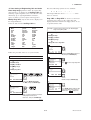
d. User Setting of Engineering Unit and Scale
Enter disp range parameters allow the engineering
unit and scale to be displayed. At Set Engr Unit, the
following engineering units can be selected from a list.
Alternately, up to eight alphanumeric characters,
spaces or slashes (/) can be input on the keypad at
Modify Engr Unit; only the first six are displayed on
the integral indicator.
Note that following symbols are not available:
# % & < > . * : + The integral indicator shows “-- -- -- -- -- --” when
these are entered.
Engr LRV and Engr URV are used to set the lower
and upper range values for the engineering unit
display. When the insrument is shipped, these are set
as specified in the order.
Select the unit from the Set Engr Unit list.
kPa
MPa
mbar
bar
psi
psia
mmH2O
mmHg
mmHgA
mmAq
mmWG
Torr
inH2O
inHg
inHgA
ftH2O
gf/cm2
kgf/cm2
kg/cm2G
kg/cm2A
atm
kg/h
t/h
m3/h
m3/min
l/h
l/min
kl/h
kl/min
Nl/h
Nl/min
Nm3/h
Nm3/min
ACFH
ACFM
SCFH
SCFM
GPH
GPM
m
mm
in
ft
kg/m3
g/cm3
Example: Set lower range value (LRV) to –50 and upper
range value (URV) to 50.
1. Device setup
4. Detailed setup
4. Display condition
4. Engr disp range
1. Engr LRV and 2. Engr URV
1
‘– 5 0’
EJX:YOKOGAWA
Engr LRV
0.0
-50
FX0302.EPS
(ENTER)
DEL
Follow the procedure below to set your own unit.
DEL
ESC
ENTER
Call up the Engr LRV Display.Set
–50, and press ENTER (F4).
2
Example: Set the engineering unit as M/h.
EJX:YOKOGAWA
Engr disp range
1 Engr LRV
2 Engr URV
3 Engr exp
4 Engr Unit
5 Engr point
HELP SEND HOME
1. Device setup
4. Detailed setup
4. Display condition
4. Engr disp range
3
7. Modify Engr Unit
EJX:YOKOGAWA
Engr URV
100.0
50
-50
100
!1
M
1
ENTER
Press
to select engr disp URV.
‘5 0’
1
(ENTER)
EJX:YOKOGAWA
Enter Engr Unit:
HELP
DEL
DEL
ESC
ENTER
M/H
(SEND)
HELP
DEL
ABORT ENTER
Set 50, and press ENTER (F4).
(ENTER)
Call up the Modify Engr Unit.
Set M/H, and press ENTER (F4).
4
EJX:YOKOGAWA
Engr disp range
1 Engr LRV
2 Engr URV
3 Engr exp
4 Engr Unit
5 Engr point
HELP SEND HOME
2
EJX:YOKOGAWA
Enter space on the
characters to be
lowercase:
M/H
M/
HELP
DEL
ABORT ENTER
×2
-50
50
!1
M
1
ENTER
(SEND)
Press SEND (F2) to send the data
to the transmitter, then check to
confirm that SEND disappears.
(ENTER)
F0322.EPS
Enter a space instead of a character
to display the character in
lowercase, and press ENTER (F4).
F0321.EPS
3-13
IM 01C25T01-01E
3. OPERATION
3.5.4
Unit for Displayed Temperature
3.5.5
When the instrument is shipped, the temperature units
are set to C (Centigrade). Follow the procedure below
to change this setting.
Unit for Displayed Static Pressure
Follow the procedure to change the static pressure unit.
Changing this parameter also changes the unit for the
static pressure display.
When this parameter is set, it also changes the temperature unit for Snsr temp at Process variables
and Amp temp at Temp sensor.
Example: Change the static pressure unit from mmH2O to
kPa.
1. Device setup
Example: Change the unit for the temperature display from
degC to degF.
4. Detailed setup
1. Sensors
1. Device setup
2. SP sensor
4. Detailed setup
3. SP Unit
1. Sensors
1
3. Temp sensor
EJX:YOKOGAWA
SP Unit
mmH2O
kg/cm2
Pa
kPa
torr
HELP SEND
3. Temp Unit
1
EJX:YOKOGAWA
Temp Unit
degC
degC
degF
Kelvin
HELP
SEND
SEND
(ENTER)
Select kPa and Press ENTER (F4).
ESC
ENTER
(ENTER)
EJX:YOKOGAWA
SP sensor
1 SP
0 mmH2O
2 SP %
0.0 %
3 SP Unit
kPa
4 A/G Select
5 SP H/L Select
High
HELP SEND HOME ENTER
2
HELP
ENTER
2
Select degF (Fahrenheit), and
Press ENTER (F4).
EJX:YOKOGAWA
Temp sensor
1 Snsr temp
2 Amp temp
3 Temp Unit
ESC
23 degC
23 degC
degF
HOME
ENTER
(SEND)
Press SEND (F2) to send the data
to the transmitter, then check to
confirm that SEND disappears.
F0324.EPS
(SEND)
Press SEND (F2) to send the data
to the transmitter, then check to
confirm that SEND disappears.
F0323.EPS
3-14
IM 01C25T01-01E
3. OPERATION
3.5.6
Test Output
CAUTION
This feature can be used to output a fixed current for
loop checks. The available range for test output
depends on the settings for the AO lower limit and
AO upper limit parameters, whose limit is from 3.6
mA (-2.5%) to 21.6 mA (110%) .
Test output continues for approximately 10
minutes, then is released automatically. Even if
the HART communicator power supply is turned
off or the communication cable is disconnected,
test output will continue for approximately 10
minutes.
Example: To output 12 mA (50%)
1. Device setup
2. Diag/Service
2. Loop test
1
EJX:YOKOGAWA
WARN-loop should be
removed from
automatic control
DEL
SET
ABORT
(OK)
OK
Set the control loop in manual
mode, and press OK (F4).
2
EJX:YOKOGAWA
Choose analog output
level
1 4mA
2 20mA
3 Other
4 End
DEL
SET ABORT ENTER
×2
(ENTER)
Select Other, and press ENTER
(F4).
Supplementary explanation.
1. 4 mA:
Outputs a 4 mA current signal
2. 20 mA:
Outputs a 20 mA current signal
3. Other:
Sets a desired output using the
alphanumeric keys
4. End: Exits
3
‘1 2’
EJX:YOKOGAWA
Output
12
(ENTER)
HELP
DEL
ABORT ENTER
Enter 12, and press ENTER (F4).
A fixed current of 12 mA is output.
4
EJX:YOKOGAWA
Fld dev output is
fixed at 12.000 mA
(OK)
HELP
DEL
SEND
ABORT
OK
Press OK (F4).
5
EJX:YOKOGAWA
Choose analog output
level
1 4mA
2 20mA
3 Other
4 End
DEL
HELP
SEND ABORT ENTER
(ENTER)
To finish the loop test, select End,
and press ENTER (F4).
6
EJX:YOKOGAWA
NOTE-loop may be
returned to automatic
control
DEL
HELP
×3
SEND
ESC
OK
(OK)
Press OK (F4).
F0325.EPS
3-15
IM 01C25T01-01E
3. OPERATION
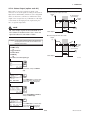
3.5.7
b. Level Adjustment—Auto, lower Pt
This zero adjustment calibrates the transmitter output
corresponding to the actual tank level. To perform this
adjustment, first use a glass gauge or the like to
determine the actual tank level, then enter the correct
data as shown below.
Sensor Trim
Each DPharp EJX series transmitter is factory characterized. Factory characterization is the process of
comparing a known pressure input with the output of
each transmitter sensor module over the entire pressure
and temperature operating range. During the characterization process, this comparison information is stored
in the transmitter EEPROM. In operation, the transmitter uses this factory-stored curve to produce a process
variable output (PV), in engineering units, dependent
on the pressure input.
DPharp span:
0 to 2500 mmH2O
Actual level:
1350 mmH2O
Transmitter output: 1383 mmH2O
2500 mmH2O
The sensor trim procedure allows you to adjust for
local conditions, changing how the transmitter calculates process variables. There are two ways to trim the
sensor: a zero trim and a full sensor trim. A zero trim
is a one-point adjustment typically used to compensate
for mounting position effects or zero shifts caused by
static pressure. A full sensor trim is a two-point
process, in which two accurate end-point pressures are
applied (equal to or greater than the range values), and
all output is linearized between them.
Actual level
1350 mmH2O
DPharp
0 mmH2O
F0327.EPS
1. Device setup
2. Diag/Service
3. Calibration
(1) Zero Trim
3. Pres sensor trim
a. Zeroing—Pres Zero trim
Pres Zero trim carries out the zero adjustment and
automatically sets the applied “0” input values to the
output value of “0,” keeping the span constant. Use
this setting when the LRV is known to be 0 mmH2O.
2. Pres Trim
1
EJX:YOKOGAWA
Select trim mode
1 Off
2 Auto, Lower Pt
3 Auto, Upper Pt
4 Manual, Lower Pt
5 Manual, Upper Pt
ABORT ENTER
1. Device setup
EJX:YOKOGAWA
Pres for trim 1383.0
Auto, Lower Pt
3. Calibration
0.000000
1350
3. Pres Sensor trim
DEL
1. Pres Zero trim
1
EJX:YOKOGAWA
WARN-LOOP should be
removed from
automatic control
‘1 3 5 0’
(ENTER)
ABORT ENTER
Enter the value of the actual level
(1350 mmH2O), and press ENTER
(F4).
F0328.EPS
c. Using External Zero-adjustment Screw
This method permits zero adjustment without the
HART communicator. Use a slotted screwdriver to turn
the zero-adjustment screw. See the hardware manual
for details.
(OK)
OK
Press OK (F4).
2
EJX:YOKOGAWA
WARN-This will affect
sensor calibration
(OK)
ABORT
Select the Auto, Lower Pt, and
press ENTER (F4).
2
2. Diag/Service
ABORT
(ENTER)
OK
Note that the parameter of Ext SW must be Enabled
to perform this adjustment. See section 3.5.11 for the
setting procedure.
Press OK (F4).
3
EJX:YOKOGAWA
Apply 0 input to
sensor
(OK)
ABORT
OK
A pressure of 0 mmH2O is applied.
Press OK (F4) after the pressure
has become stable.
F0326.EPS
3-16
IM 01C25T01-01E
3. OPERATION
(2) Full Sensor Trim—Auto Trim and Manual
Trim
Full sensor trim is carried out with a series of the
procedure of Auto, Lower Pt and Auto, Upper Pt.
Also, you can manually perform the trimming procedure in Manual, Lower Pt and Manual, Upper Pt.
b. Manual Sensor Trim
Example:
1. Device setup
2. Diag/Service
The full sensor trim is a two-point adjustment, and the
lower point adjustment should always be performed
before the upper point adjustment in order to maintain
the pitch between the zero and 100% points within the
calibration range.
3. Calibration
3. Pres sensor trim
2. Pres Trim
1
In the manual method, the reference pressure should
also be applied to the transmitter at both lower and
upper point of trim ends. Without the reference
pressure, P LTD and P UTD may not represent the
correct value of adjustment point for each.
EJX:YOKOGAWA
Select trim mode
1 Off
2 Auto, Lower Pt
3 Auto, Upper Pt
4 Manual, Lower Pt
5 Manual, Upper Pt
ABORT ENTER
×3
(ENTER)
Select Manual, Lower Pt, and
press ENTER (F4).
a. Auto Sensor Trim
Example:
For the range of 1000 to 3000 mmH2O
P LTD = 4.0 mmH2O
P UTD = 3.0 mmH2O
Suppose that a standard pressure of 1000 mmH2O is
applied and the value of the Pres for Trim in 2 is 994.0.
Correct for this output error of 6 mmH2O by adding 6
mmH2O to P LTD.
For the range of 1000 to 3000 mmH2O
1. Device setup
4.0"6.0#"2.0
2. Diag/Service
2
3. Calibration
EJX:YOKOGAWA
Pres for trim 994.0
Manual, Lower Pt
4.000000
2
3. Pres sensor trim
2. Pres Trim
DEL
1
EJX:YOKOGAWA
Select trim mode
1 Off
2 Auto, Lower Pt
3 Auto, Upper Pt
4 Manual, Lower Pt
5 Manual, Upper Pt
ABORT ENTER
ABORT ENTER
EJX:YOKOGAWA
Select trim mode
1 Off
2 Auto, Lower Pt
3 Auto, Upper Pt
4 Manual, Lower Pt
5 Manual, Upper Pt
ABORT ENTER
(ENTER)
DEL
‘1000’
×4
(ENTER)
Suppose that a standard pressure of 3000 mmH2O is
applied and the value of the Pres for Trim in 4 is 3015.0.
Firstly, obtain the slope error for the span as follows;
(ENTER)
ABORT ENTER
Enter the correction value of 2.
Then press ENTER (F4).
Select Manual, Upper Pt, and press
ENTER (F4).
2
1000.000000
1000
(ENTER)
3
Select Auto , Lower Pt, and press
ENTER (F4).
EJX:YOKOGAWA
Pres for trim 994.0
Auto, Lower Pt
‘2’
Apply a standard pressure of 1000
mmH2O to the transmitter. After
obtaining a stable pressure, press
ENTER (F4).
Slope Error #
Applied Pressure ValueValue of Pres for Trim
!(URVLRV)
Applied Pressure Value
3
EJX:YOKOGAWA
Select trim mode
1 Off
2 Auto, Lower Pt
3 Auto, Upper Pt
4 Manual, Lower Pt
5 Manual, Upper Pt
ABORT ENTER
#
×2
30003015
!(30001000) # 10
3000
Then correct for this slope error of 10 by adding 10 to
P UTD.
3.0"(10.0)#13.0
(ENTER)
Select Auto, Upper Pt, and press
ENTER (F4).
4
4
EJX:YOKOGAWA
Pres for trim 3015.0
Auto, Upper Pt
3000.000000
3000
DEL
‘3000’
EJX:YOKOGAWA
Pres for trim 3015.0
Manual, Upper Pt
3.000000
13
(ENTER)
ABORT ENTER
Apply a standard pressure of 3000
mmH2O to the transmitter. After
obtaining a stable pressure, press
ENTER (F4).
DEL
ABORT ENTER
‘13’
(ENTER)
Enter the correction value of 13.
Then press ENTER (F4).
F0348.EPS
F0329.EPS
3-17
IM 01C25T01-01E
3. OPERATION
(3) Sensor Trim for Static Pressure
For the EJX differential transmitters, zeroing and full
sensor trim of the static pressure is performed in the
same way as with the primary process variable (PV).
Note that the static pressure sensor trim should be done
only after trimming the PV.
3.5.8
Trim Analog Output
Fine current output adjustment is carried out with D/A
trim or Scaled D/A trim.
• D/A Trim
D/A trim is to be carried out if the calibration digital
ammeter does not exactly read 4.000 mA and 20.000
mA with an output signal of 0% and 100%.
• Scaled D/A Trim
Scaled D/A trim is to be carried out if the output is
adjusted using a voltmeter or a meter whose scale is
0 to 100%.
(4) Reset Trim Adjustment to Factory Setting
The Clear P snsr trim and Clear SP snsr trim
commands can reset the trim adjustment to the initial
calibrated values that were set. The amount of the
adjustment by the external zero-adjustment screw is
returned to the initial setting as well.
Example 1: For an adjustment using an ammeter (±1µA is
measurable)
1. Device setup
2 Diag/Service
3. Calibration
2. Analog output trim
1. D/A trim
1
EJX:YOKOGAWA
Analog output trim
1 D/A trim
2 Scaled D/A trim
3 Clear D/A trim
HELP
SAVE
HOME
OK
Select the D/A trim item.
2
EJX:YOKOGAWA
WARN-Loop should be
removed from
automatic control
(OK)
Press OK (F4).
DEL
SET
ABORT
OK
3
EJX:YOKOGAWA
Connect reference
meter
(OK)
HELP
DEL
ABORT
OK
Connect the ammeter (±1µA is
measurable), and press OK (F4).
4
EJX:YOKOGAWA
Setting fld dev
output to 4mA
(OK)
HELP
DEL
ABORT
OK
Press OK (F4), and the transmitter
outputs a 0% output signal.
5
‘4 . 1 1 5’
EJX:YOKOGAWA
Enter meter value
4.000
4.115
(ENTER)
HELP
DEL
ESC
ENTER
Ammeter reading: 4.115
Enter the read value 4.115 of the
ammeter, and press ENTER (F4).
(The output of the transmitter
changes.)
F0330.EPS
3-18
IM 01C25T01-01E
3. OPERATION
6
Example 2: To adjust using a voltmeter
EJX:YOKOGAWA
Fld dev output 4.000
mA equal to reference
meter?
1 Yes
2 No
HELP
SET
ABORT ENTER
1. Device setup
(ENTER)
2 Diag/Service
Ammeter reading: 4.000
3. Calibration
If the reading on the ammeter is
4.000 mA, select YES and press
ENTER (F4).
If the reading is not 4.000 mA,
select item 2. NO. Repeat steps 4
and 5 until the ammeter reads
4.000 mA.
7
2. Analog output trim
2. Scaled D/A trim
1
EJX:YOKOGAWA
Analog output trim
1 D/A trim
2 Scaled D/A trim
3 Clear D/A trim
EJX:YOKOGAWA
Setting fld dev
output to 20mA
HELP
(OK)
DEL
SET
ABORT
OK
EJX:YOKOGAWA
WARN-Loop should be
removed from
automatic control
DEL
ABORT ENTER
ABORT ENTER
SET
ABORT
OK
EJX:YOKOGAWA
Trim will be scaled
from 4.000 to 20.000
1 Proceed
2 Change
Ammeter reading: 19.050
HELP
EJX:YOKOGAWA
Fld dev output 20.000
mA equal to reference
meter?
1 Yes
2 No
DEL
(OK)
3
Carry out the same procedures as
those described under 4 and 5 .
9
DEL
ABORT ENTER
(ENTER)
Select Change, and press ENTER
(F4).
When item 3. Proceed is selected,
D/A trim must be carried out.
4
Ammeter reading: 20.000
‘1’
EJX:YOKOGAWA
Set scale- Lo output
value
4.000000
1
Returning fld dev to original
output appears.
10
(ENTER)
EJX:YOKOGAWA
NOTE-Loop may be
returned to automatic
control
HELP
Select the Scaled D/A trim item.
Press OK (F4).
(ENTER)
HELP
OK
‘1 9.0 5 0‘
EJX:YOKOGAWA
Enter meter value
20.000
19.050
DEL
HOME
2
Press OK (F4), and the transmitter
outputs a 100% output signal.
8
HELP
SET
DEL
ESC
OK
HELP
DEL
ABORT ENTER
(OK)
Press OK (F4).
5
F0331.EPS
Enter the value read on the meter
when the signal is 4 mA. In this
case, Enter the value of the voltage
across a 250 Ω resistor (1 V), and
press ENTER (F4).
‘5’
EJX:YOKOGAWA
Set scale- Hi output
value
20.000000
5
(ENTER)
HELP
DEL
ABORT ENTER
6
Enter the value read on the meter
when the signal is 20 mA. Then,
enter 5, and press ENTER (F4).
EJX:YOKOGAWA
Trim will be scaled
from 1.000 to 5.000
1 Proceed
2 Change
(ENTER)
HELP
SET
ABORT ENTER
Select Proceed and press ENTER
(F4).
7
EJX:YOKOGAWA
Connect reference
meter
(OK)
DEL
SET
ABORT
OK
Connect the voltmeter, and press
OK (F4).
OK
Press OK (F4). A 0% output signal
is output.
8
EJX:YOKOGAWA
Setting fld dev
output to 4mA
(OK)
HELP
DEL
ABORT
F0332.EPS
3-19
IM 01C25T01-01E
3. OPERATION
3.5.9
9
When the burst mode is set on, the transmitter continuously sends stored data. Either the pressure value, %
range/current value, or current/process variables can be
selected and sent. The data is sent approximately three
times per second as a digital signal when the transmitter is set in burst mode. When data is being sent in
burst mode, other operations can be performed with the
HART communicator.
(ENTER)
HELP
DEL
ABORT ENTER
Voltmeter reading: 1.010
Enter the reading of the voltmeter
(1.010), and press ENTER (F4).
(The output of the transmitter
changes.)
10
EJX:YOKOGAWA
Scaled output: 1.000
equal readout
device?
1 Yes
2 No
HELP
DEL
Setting of Burst Mode
(ENTER)
ABORT ENTER
1. Device setup
Voltmeter reading: 1.000
If the reading on the voltmeter is
1.000, select Yes and press ENTER
(F4).
If the reading is not 1.000, select
No. Repeat steps 8 and 9 until
the voltmeter reads 1.000 V.
4. Detailed setup
3. Output condition
3. HART output
3. Burst mode and 4. Burst option
11
1
EJX:YOKOGAWA
Setting fld dev
output to 20mA
EJX:
Burst option
PV
PV
% range/current
Process vars/crnt
(OK)
HELP
SET
ABORT
OK
12
Press OK (F4). A 100% output
signal is output.
HELP
ESC
ENTER
DEL
ESC
ENTER
(ENTER)
ABORT ENTER
Voltmeter reading: 5.210
Enter the reading of the voltmeter
(5.210), and press ENTER (F4).
EJX:YOKOGAWA
Scaled output: 5.000
equal readout
device?
1 Yes
2 No
DEL
EJX:
Burst mode
Off
On
Off
(ENTER)
ABORT ENTER
DEL
HELP
Voltmeter reading: 5.000
DEL
(ENTER)
Call up the Burst mode and set to
On.
Select Yes and press ENTER (F4).
“Returning fid dev to
original output”
Call up the Burst option, and set
the data to be sent.
• PV: Primary variable (Pressure
value)
• % range/current: Output in % and
mA
• Process vars/crnt: Output in mA
and process variables (pressure
value, static pressure value, and
sensor temp value)
2
13
HELP
DEL
(ENTER)
‘5 . 2 1’
EJX:YOKOGAWA
Enter meter value
5.000000
5.210
HELP
Burst Mode
‘1 . 0 1’
EJX:YOKOGAWA
Enter meter value
1.000000
1.010
3
14
EJX:YOKOGAWA
NOTE-Loop may be
returned to automatic
control
HELP
DEL
ABORT
OK
EJX:
HART output
1 Poll addr
2 Num req preams
3 Burst mode
4 Burst opiton
(OK)
HELP
Press OK (F4).
SEND
HOME
0
5
On
PV
ENTER
(SEND)
Press SEND (F2) to send the data
to the transmitter, then check to
confirm that SEND disappears.
F0333.EPS
F0334.EPS
To release Burst Mode, call up the Burst mode
display and set it to Off.
3-20
IM 01C25T01-01E
3. OPERATION
3.5.10 Multidrop Mode
Example:
“Multidropping” transmitters refers to the connection
of several transmitters to a single communications
transmission line. Up to 15 transmitters can be connected when set in the multidrop mode. To activate
multidrop communication, the transmitter address must
be changed to a number from 1 to 15. This change
deactivates the 4 to 20 mA analog output, sending it to
4 mA. The alarm current is also disabled.
Communication when set in multidrop mode
1
HART Communicator
Online
1 EJX110A-1
2 EJX110A-2
3 EJX110A-3
HELP
SET
HOME
OK
2
EJX:EJX110A-1:
Online
1 Device setup
2 Pres
0.0 mmH2O
3 AO
4.000 mA
4 LRV
0.0 mmH2O
5 URV
3500.0 mmH2O
DEL
SET ABORT
OK
Setting of Multidrop Mode
1. Device setup
4. Detailed Setup
3
HART Communicator
1 Offline
2 Online
3 Frequency Device
4 Utility
3. Output condition
3. HART Output
1. Poll addr
EJX:
Poll addr
0
1
HELP
DEL
ESC
ENTER
HELP
Call up the Poll addr and set the
polling address. (a number from 1 to
15)
And press SEND (F2) to send the
data.
DEL
ABORT
OK
(1) The HART communicator
searches for a transmitter that is
set in multidrop mode when it is
turned on.
When the HART communicator
is connected to the transmitter,
the polling address and the tag
will be displayed (display 1 ).
(2) Select the desired transmitter.
After that, normal
communication to the selected
transmitter is possible. However,
the communication speed will be
slow (display 2 ).
(3) To communicate with another
transmitter, turn off the power
once and then turn on it again,
or call up display 3 and select
Online.
(4) Display 1 will appear. Select
the desired transmitter.
F0336.EPS
To release multidrop mode, follow the procedure
below.
• Then make sure the communicator setting is as follows.
1. Call up the Poll addr display and set the address
to 0.
2. Call up the Polling display and set Ask Before
Polling.
2. Online
4. Utility
1. Configure Communication
1. Polling
HART Communicator
Polling
Ask Before Polling
Ask Before Polling
Always Poll
Digital Poll
Poll Using Tag
HELP
DEL
ESC
ENTER
(ENTER)
Confirm that Always Poll, Ask
Before Polling, or Digital Poll is
specified, and press ENTER (F4).
F0335.EPS
NOTE
1. When the polling option is set as Never Poll
or Poll Using Tag, the online menus cannot
be called up and displayed. Be sure to select
a polling option such as Ask Before Polling.
2. When the same polling address is set for two
or more transmitters in multidrop mode,
communication with these transmitters is
disabled.
3-21
IM 01C25T01-01E
3. OPERATION
3.5.11 External Switch Mode
3.5.12 CPU Failure Burnout Direction and
Hardware Write Protect
Follow the procedure below to enable or inhibit zero
point adjustment by means of the zero-adjustment
screw on the transmitter.
There are two slide switches on the CPU assembly
board. One sets the burnout direction at CPU failure,
and the other sets a write protection function which
disables parameter changes through the use of a
handheld terminal or some other communication
method.
This is set to Enabled when the instrument is shipped.
Example: Set the mode to inhibit zero adjustment by means
of the external zero-adjustment screw.
CPU assembly
1. Device setup
Burnout direction switch
4. Detailed setup
5. Device information
1. Field device info
BO H
L
WR E
D
Slide switch
9. Ext SW
Write protection switch
1
EJX:
Ext SW
Enabled
Disabled
Enabled
HELP
SEND
Burnout direction switch (BO)
ESC
ENTER
Burnout Direction
Switch Position
(ENTER)
H
L
H
L
E
D
E
D
Select Disabled and press ENTER
(F4).
Burnout Direction
2
EJX:
Field device info
5 Model 1
6 Model 2
7 Model 3
8 Write Protect
No
9 Ext SW
Disabled
HELP SEND HOME ENTER
HIGH
LOW
Hardware write protection switch (WR)
(SEND)
Write Protection
Switch Position
Press SEND (F2) to send the data
to the transmitter, then check to
confirm that SEND disappears.
F0337.EPS
Write Protection
H
L
H
L
E
D
E
D
NO
(Write enabled)
YES
(Write disabled)
F0340.EPS
The parameter of AO alm typ parameter displays the
status of 4-20 mA DC output if a CPU failure occurs.
In case of a failure, communication is disabled.
Standard specifications
The burnout direction switch is set to HIGH. If a
failure occurs, the transmitter outputs a 110% or higher
signal.
Option code /C1
The burnout direction switch is set to LOW. If a failure
occurs, a –5% or lower output is generated.
Example: Confirming the burnout direction at the CPU
failure.
1. Device setup
4. Detailed setup
3. Output condition
2. Analog output
EJX:
Analog output
1 Loop test
2 D/A trim
3 Scaled D/A trim
4 Clear D/A trim
5 AO alm typ
HELP SAVE HOME
High
EXIT
5. AO alm typ
F0341.EPS
3-22
IM 01C25T01-01E
3. OPERATION
3.5.13 Software Write Protect
5
EJX:
It changed the state
of protection related
password.
EJX configured data is saved by using a write protect
function. The write protect status is set to “Yes” when
8 alphanumeric characters are entered in the New
password field and transferred to the transmitter.
When write protect is set to “Yes,” the transmitter does
not accept parameter changes. When the same eight
alphanumeric string entered in the New password
field is also entered in the Enable wrt 10min field
and transferred to the transmitter, it will be possible to
change transmitter parameters during a 10 minute
period.
HELP
DEL
ABORT
OK
(OK)
Press OK (F4).
Write Protect status changes from
NO to YES.
F0355.EPS
(2) Entering Password to Enable the Parameter Changes
Example: Enter the password of 1 2 3 4
To change the transmitter from the write protect “Yes”
status back to Write protect “No” status, use Enable
wrt 10min to first release the write protect function
and then enter eight spaces in the New password
field.
1
EJX:
Hot key
1 keypad input
2 Wrt protect menu
HELP
The software write protection does not aflect the
function of external zero adjustment screw.
SEND
ESC
ENTER
Press Hot key.
Select Wrt protect menu.
2
EJX:
Wrt protect menu
1 Write Protect
No
2 Enable wrt 10min
3 New password
4 Software seal
Keep
To disable the external zero adjustment screw, select
Disabled in the Ext SW field before activating the
software write protection. Refer to subsection 3.5.11.
HELP
(1) Setting Password
SEND
ESC
Select Enable wrt 10min.
ENTER
3
Example: Set the password to 1 2 3 4
EJX:
Enter current
password to enable to
write for 10
minutes:
.
1234
HELP
1
DEL
ABORT ENTER
(ENTER)
Set 1 2 3 4
ENTER (F4).
EJX:
Hot key
1 keypad input
2 Wrt protect menu
HELP
SEND
ESC
(DEL)
ENTER
EJX:
Wrt protect menu
1 Write Protect
No
2 Enable wrt 10min
3 New password
4 Software seal
Keep
SEND
ESC
4
Press Hot key.
Select Wrt protect menu.
EJX:
Released the write
protection for 10
minutes.
Press ENTER (F4).
HELP
Select New password.
1234
OK
EJX:
If you wish to
release completely,
you have to change
password to all of
spaces.
ABORT ENTER
HELP
(ENTER)
Set 1 2 3 4
ENTER (F4).
ABORT ENTER
ABORT
OK
Press OK (F4), and the write protect
is released for 10 minutes.
F0339.EPS
(3) Releasing Password
To release the password completely, enter spaces in the
New password field while the write protect function
is released.
4
EJX:
Re-enter new password
withing 30 seconds:
1234
1234
DEL
(OK)
and press
(DEL)
DEL
ABORT
5
×4
HELP
DEL
ENTER
EJX:
Enter new password to
change state of write
protect:
DEL
(OK)
×2
3
HELP
and press
×4
2
HELP
.
(ENTER)
Set the new password again, and
press ENTER (F4).
F0338.EPS
3-23
IM 01C25T01-01E
3. OPERATION
(4) Software Seal
When you lose the password that has been registered, it
is possible to release the Write Protect mode by
using the general use password: “YOKOGAWA.”
When the password is used, the status shown in the
parameter of Software seal is changed from “KEEP”
to “BREAK.” The status returns to “KEEP” by
entering a newly set password at Enable wrt 10min.
2
EJX:
S.C. menu
1 S.C.
Disabled
2 Num of points
5
3 point setting
4 X Start
0.00 %
5 Y Start
0.00 %
HELP SEND HOME ENTER
(SEND)
Press SEND (F2) to send the data
to the transmitter, then check to
confirm that SEND disappears.
F0356.EPS
3.5.14 Signal Characterizer
Example: Set the first coordinates (X1, Y1) as (12, 14) in %.
This function is used to compensate the output for nonlinear applications. The characterized values are
applied to the 4-20 mA output. For the measured
pressure, a maximum of nine coordinates can be
specified between 0-100%. Perform the coordinate
settings while the S.C. at S.C. menu parameter is
Disabled.
1. Device setup
4. Detailed setup
2. Signal condition
S.C. menu
3. Point setting
1
EJX:
Select one
1 List
2 Edit all points
3 Edit one point
4 Exit
To apply the settings to the output, set the S.C.
parameter to Enabled.
Note that the EJX rejects the activation of the function
by AL. 60 with the following transmitter’s status:
×2
ABORT ENTER
(ENTER)
Select Edit one point, and press
ENTER (F4).
• When the specified coordinates of x and y are not
incremental as the input increases.
• When the output mode of the output signal is set as
Sq root; at the same time, the low cut mode is set to
Linear.
2
EJX:
Specify S.C. point to
set value
1
1
(ENTER)
Press ENTER (F4).
DEL
ABORT ENTER
3
EJX:
X1
10.00 %
12
Y
100%
INPUT
HELP
OUTPUT
Input pressure in %
DEL
‘ 12 ’
ESC
ENTER
(ENTER)
Enter 12 and press ENTER (F4).
Characterized value
4
0%
100% X
EJX:
Y1
10.00 %
14
F0342.EPS
Example: Set the number of coordinates on the line graph to
5.
HELP
DEL
‘ 14 ’
ESC
ENTER
(ENTER)
Enter 14 and press ENTER (F4).
1. Device setup
F0344.EPS
4. Detailed setup
2. Signal condition
S.C. menu
2. Num of points
1
EJX:
Num of points
0
5
HELP
DEL
‘5’
ESC
ENTER
(ENTER)
Enter 5 and press ENTER (F4).
F0343.EPS
3-24
IM 01C25T01-01E
3. OPERATION
3.5.15 Process Alarm
Example: Set the signal characterizer to Enabled.
The function is used to display the alarm codes when
the input pressure exceeds the specified value within
the calibration range. The same is available for the
input static pressure and the capsule temperature on the
pressure sensor. Refer to table 4.2.1 Alarm Message
Summary for the specific alarm code to be generated.
1. Device setup
4. Detailed setup
2. Signal condition
S.C. menu
1. S.C.
1
Example: Set the alert mode from OFF to Hi. Al Detect for
the input pressure.
EJX:
S.C
Disabled
Disabled
Enabled
1. Device setup
HELP
DEL
ESC
ENTER
(ENTER)
4. Detailed setup
Select Enabled, and press ENTER
(F4).
3. Output condition
2
4. Process Alerts
EJX:
S.C. menu
1 S.C.
Enabled
2 Num of points
5
3 Point setting
4 X Start
0.00 %
5 Y Start
0.00 %
HELP SEND HOME ENTER
1. Pres Alert mode
1
(SEND)
EJX:
Pres Alert mode
Off
Off
Hi. Al Detect
Lo. Al Detect
Hi/Lo. Al Detect
HELP
DEL
ESC
Press SEND (F2) to send the data
to the transmitter, then check to
confirm that SEND disappears.
F0345.EPS
ENTER
(ENTER)
Select Hi. Al Detect, and press
ENTER (F4).
2
EJX:
Process Alerts
1 Pres Alert mode
2 Config Pres Alerts
3 SP Alert Mode
Off
4 Config SP Alerts
5 Temp Alert Mode
HELP SEND HOME ENTER
(SEND)
Press SEND (F2) to send the data
to the transmitter, then check to
confirm that SEND disappears.
F0346.EPS
Example: Set the higher alert value of 75 for alarm
generation.
1. Device setup
4. Detailed setup
3. Output condition
4. Process Alerts
2. Config Pres Alerts
1. Hi Alert Val
1
EJX:
Hi Alert Val
100.000 kPa
75
HELP
DEL
ESC
‘ 75 ’
ENTER
(ENTER)
Enter 75, and press ENTER (F4).
2
EJX:
Config Pres Alerts
1 Hi Alert Val
2 Lo Alert Val
3 LSL
-100.000 kPa
4 USL
100.000 kPa
HELP
SEND
HOME
ENTER
(SEND)
Press SEND (F2) to send the data
to the transmitter, then check to
confirm that SEND disappears.
F0347.EPS
3-25
IM 01C25T01-01E
3. OPERATION
3.5.16 Status Output (option code AL)
Example: Status output operation of ON WHEN AL. DETECT
This feature is used for a transistor output (open
collector) of an on/off signal according to the status of
high and low alarm limits, which are user-configurable
values as shown in 3.5.15 Process Alarm. The status
output can be assigned as any combination of the high
or low limits of the input pressure, input static pressure, or capsule temperature.
Status output for higher alert value
Output
(%)
5% of hysteresis
(5C for heat)
Setting
value
NOTE
Time (t)
On
No status output signal has been defined for a
CPU failure or hardware error. Use a 4-20 mA
signal to indicate a transmitter’s failure.
Status output
On
Off
Status output for lower alert value
Output
(%)
Example: Set the status output to output an off signal when
the input pressure exceeds 75 kPa with the alert
mode of Hi. Al Detect.
Setting
value
5% of hysteresis
(5C for heat)
1. Device setup
4. Detailed setup
3. Output condition
Time (t)
On
4. Process Alerts
7. DO Config
Status output
2. DO Select and 3. DO Signal type
On
Off
F0350.EPS
1
EJX:
DO Select
Pres
Off
Pres
SP
Temp
ESC
ENTER
(ENTER)
Select Pres, and press ENTER
(F4).
2
EJX:
DO Config
1 Digital Output
2 DO Select
3 DO Signal type
4 DO Test
HELP
SEND
HOME
Off
Pres
ENTER
(SEND)
Press SEND (F2) to send the data
to the transmitter, then check to
confirm that SEND disappears.
3
EJX:
DO Signal type
ON WHEN AL. DETECT
ON WHEN AL. DETECT
OFF WHEN AL. DETECT
ESC
ENTER
(ENTER)
Select OFF WHEN AL. DETECT,
and press ENTER (F4).
4
EJX:
DO Config
1 Digital Output
2 DO Select
3 DO Signal type
4 DO Test
HELP
SEND
HOME
Off
Pres
ENTER
(SEND)
Press SEND (F2) to send the data
to the transmitter, then check to
confirm that SEND disappears.
F0349.EPS
3-26
IM 01C25T01-01E
3. OPERATION
EJX118A
3.5.17 Capillary Fill Fluid Density Compensation
L
h
For transmitters with diaphragm seals, this function is
used to compensate the zero shift caused by the
ambient temperature effect on the capillary tubes.
(")
Transmitter
0
H
The following equation indicates the relationship
between the calculated output value and the compensating constant K (%/C) with the measured ambient
temperature at the capsule module.
EJX438A
Transmitter
L
Compensated output#output"K!Tamb
h
(")
(1) Temperature Compensation Mode Setup
When using this function, set T.Z. Cmp mode to ON
to enable or OFF to disable. To set to ON, follow the
procedure below.
H
0
()
Transmitter
L
h
Note: When the transmitter is positioned lower than the
diaphragm seal part, the value of “h” must have a
negative sign ().
F0353.EPS
Example: Set the temperature compensation mode to ON.
1. Device setup
4. Detailed setup
Example: Enter K value obtained from the equation (a).
A value haivng up to 3 decimal places may be
specified.
2. Signal condition
T.Z. Cmp menu
When h#"3 m, Fill fluid code A, span#15 kPa,
K#("3)!0.00745$15!100#0.149
1. T.Z. Cmp mode
1
EJX:
T.Z. Cmp mode
Off
Off
On
HELP
DEL
1. Device setup
4. Detailed setup
ESC
ENTER
2. Signal condition
(ENTER)
T.Z. Cmp menu
Select On, and press ENTER (F4).
2. Temp Zero
2
EJX:
T.Z. Cmp menu
1 T.Z. Cmp mode
2 Temp Zero
HELP
SEND
HOME
1
On
ENTER
‘ 0.149 ’
EJX:
Temp Zero
0.000 %/degC
-0.149
(SEND)
Press SEND (F2) to send the data
to the transmitter, then check to
confirm that SEND disappears.
HELP
DEL
ESC
ENTER
(ENTER)
Enter 0.149 and press ENTER
(F4).
F0351.EPS
(2) Zero Shift Compensation Setup
Obtain the K compensating value from the equation (a)
below, and enter the value to Temp Zero.
2
EJX:
T.Z. Cmp menu
1 T.Z. Cmp mode
2 Temp Zero
K= – h×B ×100 ................ (a)
Span
HELP
where,
B: Constant value of fill fluid (See Table A.)
SEND
HOME
On
(SEND)
ENTER
Press SEND (F2) to send the data
to the transmitter, then check to
confirm that SEND disappears.
F0354.EPS
Note 1: The function is performed using a built-in temperature sensor
in the transmitter body. The temperature deviation between
the transmitter body and capillaries should be minimized to
achieve optimal performance of the function.
Note 2: When the span changes, reenter the newly obtained value of
K to Temp Zero.
span: |URV–LRV|
h: Distance from high pressure side to low
pressure side (m)
EJX118A: Distance from high side of diaphragm seal to low side of diaphragm seal.
EJX438A: Distance from diaphragm seal (high
side) to position of transmitter (low side).
3-27
IM 01C25T01-01E
3. OPERATION
Constant value [B]
Table A. Constant value [B] of fill fluid
Fill fluid
code
mmH2O
kgf/cm2
kPa
mBar
atm
inH2O
psi
mmHg
A, C
B
D
E
0.76
0.000076
0.00745
0.07453
0.000074
0.02992
0.00108
0.05592
0.87
0.000087
0.00853
0.08532
0.000084
0.03425
0.00124
0.06401
1.45
0.000145
0.01422
0.14220
0.000140
0.05709
0.00206
0.10669
0.75
0.000075
0.00736
0.07355
0.000073
0.02953
0.00167
0.05518
T0304.EPS
Note 3: Select the unit of constant value of [B] from the actual unit
used for the transmitter in operation.
3-28
IM 01C25T01-01E
4. SELF-DIAGNOSTICS
4.
SELF-DIAGNOSTICS
4.1 Self-Diagnostics
4.1.1
Diagnostic by “status”
1. Device setup
Identify Problems by Using the
Communicator
2. Diag/Service
The HART communicator can be used to run selfdiagnostics on a transmitter and check for incorrect
data settings.
1. Test device
The Self test and Status commands are available for
self-diagnostics. When Self test is run, the integral
indicator shows an error code and alarm message if the
transmitter detects any illegal parameter settings and
functional faults. See table 4.2.1 Alarm Message
Summary for probable causes and countermeasures. If
the specific diagnostic item is known for the check,
you can directly call up the item by using the Status
command. See table 4.2.1 to determine the status
group.
1
1. Status
6. Status group 6
EJX:
Status
2 Status group 2
3 Status group 3
4 Status group 4
5 Status group 5
6 Status group 6
HELP SAVE HOME
OK
Call up Status, and select Status
group 6.
2
EJX:
Status group 6
Illegal P LRV
Illegal P URV
Illegal P SPAN
P SPAN trim err
P ZERO trim err
DEL
SET ABORT
On
Off
Off
Off
Off
EXIT
If there is no error, the result of
diagnostics is indicated as Off. If On
is indicated, a countermeasure for
that error is necessary.
The HART communicator diagnoses every command
you make. When a faulty command or keypad input is
performed, an error message appears. See table 4.2.2
HART Commnicator Error Messages for the details.
F0402EPS
4.1.2
Checking with Integral Indicator
Diagnostic by “self test”
1. Device setup
NOTE
2. Diag/Service
If an error is detected by running self-diagnostics, an error number is displayed on the integral
indicator. If there is more than one error, the
error number changes at three-second intervals.
See table 4.2.1 regarding the alarm codes.
1. Test device
2. Self test
1
EJX:
Test device
1 Status
2 Self test
HELP
SAVE
HOME
OK
Call up Test device, and select Self
test.
2
If no error is detected, Self test OK
is displayed.
If there is an error, an error
message appears.
EJX:
Self test OK
DEL
SET
ABORT
OK
F0401.EPS
F0403.EPS
Figure 4.1.2 Integral Indicator
4-1
IM 01C25T01-01E
4. SELF-DIAGNOSTICS
4.2 Alarms and Countermeasures
Table 4.2.1 Alarm Message Summary
Integral
indicator
HART communicator
display
Output operation
during error
Cause
P sensor error
Sensor problem.
CT sensor error
Capsule temperature sensor
problem.
Cap EEPROM error
Capsule EEPROM problem.
AT sensor error
Amplifier temperature sensor
problem.
Amp EEPROM error
Amplifier EEPROM problem.
CPU board error
Amplifier problem.
No device ID
No device ID is found.
Continues to operate and
output.
AL. 10
PRESS
P outside limit
Input is outside measurement
range limit of capsule.
Outputs AO upper limit or AO
lower limit.
AL. 11
ST. PRSS
SP outside limit
Static pressure exceeds
limit.
Continues to operate and
output.
AL. 12
CAP. TMP
CT outside limit
Capsule temperature is outside
range (–50 to 130°C).
AL. 13
AMP. TMP
AT outside limit
Amplifier temperature is outside
range (–50 to 95°C).
AL. 30
RANGE
P over range
Output is outside upper or lower
range limit value.
Outputs AO upper limit or AO
lower limit.
AL. 31
SP. RNG
SP over range
Static pressure exceeds
specified range.
Continues to operate and
output.
AL. 35
P. HI
P high alarm
Input pressure exceeds specified
threshold.
AL. 36
P. LO
P low alarm
AL. 37
SP. HI
SP high alarm
AL. 38
SP. LOW
SP low alarm
AL. 39
TMP. HI
CT high alarm
AL. 40
TMP. LO
CT low alarm
AL. 50
P. LRV
Illegal P LRV
AL. 51
P. URV
Illegal P URV
AL. 52
P. SPN
Illegal P SPAN
AL. 53
P. ADJ
P SPAN trim err
AL. 54
SP. RNG
Illegal SP LRV
AL. 01
CAP. ERR
AL. 02
AMP. ERR
Countermeasure
Outputs the signal (High or Low) Replace capsule when
set with burnout direction
error keep appearing error
switch. [status output: undefined] even after restart.
Replace capsule.
1
Replace amplifier.
2
Check input or replace
capsule when necessary.
3
Use heat insulation or
make lagging to keep
temperature within
range.
Check input and range
setting, and change
them as needed.
4
Check input.
Input static pressure exceeds
specified threshold.
5
Check capsule
temperature.
Detected temperature exceeds
specified threshold.
Specified value is outside of
setting range.
Status
group
Holds output immediately
before error occurred.
Check settings and change
them as needed.
Continues to operate and
output.
Adjust settings and change
them as needed.
Continues to operate and
output holding static
pressure in %.
Check settings and change
them as needed.
Continues to operate and
output.
Adjust settings and change
them as needed.
6
P ZERO trim err
Illegal SP URV
Illegal SP SPAN
AL. 55
SP. ADJ
SP SPAN trim err
AL. 60
SC. CFG
SC config error
AL. 79
OV. DISP
SP ZERO trim err
7
Specified values or settings do
not meet the conditions.
Continues to operate and output Check settings and change
them as needed.
without signal characterizing.
Displayed value exceeds
limit.
Continues to operate and
output.
T0401.EPS
4-2
IM 01C25T01-01E
4. SELF-DIAGNOSTICS
Table 4.2.2 HART Communicator Error Messages
Error message
Probable cause
Countermeasure
Change the setting.
Invalid selection
—
Value was too high
Set value is too high.
Value was too low
Set value is too low.
Too few data bytes received
—
—
In write protect mode
Operation is set in the Write Protect mode.
—
Lower range value too high
LRV set point is too high.
Change the range.
Lower range value too low
LRV set point is too low.
Upper range value too high
URV set point is too high.
Upper range value too low
URV set point is too low.
Span too small
Set span is too small.
Applied process too high
Applied pressure is too high.
Applied process too low
Applied pressure is too low.
New lower range value pushed upper
range value over upper senser limit
The shift of URV according to the new
LRV setting exceeds USL.
Excess correction attempted
Adjust the applied
pressure.
Change the URV setting
within the range of USL.
Amount of correction is too much.
Adjust the amount.
Lowercase conversion not succeeded
Characters are not convertible. e.g. %
Correct the setting.
Not in fixed current mode
The fixed current mode is desired but not
set in that mode.
Set in the fixed current
mode.
In multidrop mode
Operation is set in the multi-drop mode.
—
Not write protect mode
Operation is set without a password.
—
Lower range value and upper range value
out of limits
Set value is outside lower or upper range
limit.
Change the setting.
T0402.EPS
4-3
IM 01C25T01-01E
5. PARAMETER SUMMARY
5.
PARAMETER SUMMARY
Function
Analog output
Analog output trim
Bi-directional mode
Burst mode
Burst operation option
Damping
Date
Descriptor
Device information
Display setup
Error log
Loop test
Low cut
Message
Number of requested
preambles
Piping orientation
Poll address
Process Alert
Label
Item
Contents
AO alm typ
AO lower limit
AO upper limit
Auto recover
Clear D/A trim
D/A trim
Scaled D/A trim
Bi-dir mode
Burst mode
Burst option
Pres Damp
Analog output alarm type
Lower limit of analog output
Upper limit of analog output
Auto-recover from hardware error
Reset analog output trim
Analog output trim with ammeter
Analog output trim with voltmeter
Bi-directional mode
Burst mode
Burst option
Damping time constant at amplifier
High or Low
3.6000 to 21.6000 mA
3.6000 to 21.6000 mA
Off or On
Quick resp
Date
Descriptor
Dev id
Distributor
Drain vent matl
Extra No.
Ext SW
Fill fluid
Final asmbly num
Fld dev rev
Gasket matl
Isoltr matl
LSL
Mftr Date
Min Span
Model 1
Model 2
Model 3
Num of RS
Process Conn matl
Process Conn size
Process Conn type
RS fill fluid
RS Isoltr matl
RS type
Serial No.
Software rev
Style No.
Universal rev
USL
Bar indicator
Disp Out 1
Disp Out 2
Disp Out 3
Disp Out 4
Disp Pres % fnctn
Quick response
Date
Descriptor
Device ID
Yokogawa
Drain and vent plug material
Customization number
External zeroing permission
Fill fluid
Final assembly number
Field device revision
Gasket material
Capsule material
Lower sensor limit
Manufactured date
Minimum span
Memo field for MS code 1
Memo field for MS code 2
Memo field for MS code 3
Number of remote seal
Process connection material
Process connection size
Process connection type
Fill fluid of remote seal
Remote seal material
Remote seal type
Serial number
Software revision
Style number
Universal revision
Upper sensor limit
Bar indicator
LCD output 1
LCD output 2
LCD output 3
LCD output 4
% display mode
Off or On
Pres, Pres %, Engr Pres, SP, or SP %
Pres, Pres %, Engr Pres, SP, SP %, or Not used
Pres, Pres %, Engr Pres, SP, SP %, or Not used
Pres, Pres %, Engr Pres, SP, SP %, or Not used
Linear or Sq root
Disp Pres % Reso
Engr exp
% display resolution
Exponents
Normal or High resolution
---, !10, !100, or !1000
Engr LRV
Engr point
Engr URV
Modify Engr Unit
Pres disp point
Set Engr Unit
SP disp point
Error log Clear
Error log view
Loop test
Low cut
Low cut mode
Message
Num req preams
User set lower range value
Decimal place for user set
User set upper range value
User set engineering unit
Decimal place for pressure
Engineering unit select
Decimal place for static pressure
Clear error records
Error records
Test output setting
Low cut
Low cut mode
Message
Number of requested preambles
32000 to 32000, unit specified in Set Engr Unit
0 to 4
32000 to 32000, unit specified in Set Engr Unit
H/L Swap
Poll addr
Digital Output
DO Select
DO Signal type
DO Test
Hi Alert Val
Lo Alert Val
Pres Alert mode
SP Alert mode
SP Hi Alert Val
Impulse piping accessing direction
Poll address for multidrop use
Display of contact output
Contact output select
Signal type select
Test output contact
High side alert value of pressure
Low side alert value of pressure
Alert mode for pressure
Alert mode for static pressure
High side alert value of static pressure
SP Lo Alert Val
Temp Alert mode
Temp Hi Alert Val
Temp Lo Alert Val
Low side alert value of static pressure
Alert mode for temperature
High side alert value of temperature
Low side alert value of temperature
Off or On
Off or On
PV, % range/current, or Process vars/cmt
0.00 to 100.00 sec
On or Off
**/**/**
16 alphanumerics
Disabled or Enabled
Default value
3.6000 mA
21.6000 mA
On
Off
Off
As specified or
2.00 sec
Off
As specified
Enabled
16 alphanumerics
16 alphanumerics
16 alphanumerics
Style number of product
On
Pres %
Not used
Not used
Not used
As specified or
Linear
Normal
As specified or
--As specified
2
As specified
As specified
2
0 to 4
See section 3.5.3d
0 to 4
2
Log1 (latest) to log4
Within AO lower and upper limits
0.00 to 20.00%
Linear or Zero
32 alphanumerics
10.00%
Linear
As specified
Normal or Reverse
0 to 15
Off or On
Off, P Alarm, SP Alarm, P or SP Alarm
On When Al Detect or Off When Al Detect
Off, On, or Exit
LSL10% to USL"10% minus 5% hysteresis
LSL10% to USL"10% plus 5% hystereis
Off, Hi Al Detect, Lo Al Detect, or Hi/Lo Al Detect
Off, Hi Al Detect, Lo Al Detect, or Hi/Lo Al Detect
SP LSL10% to SP USL"10% minus 5%
hysteresis
SP LSL10% to SP USL"10% plus 5% hystereis
Off, Hi Al Detect, Lo Al Detect, or Hi/Lo Al Detect
50 to 130
50 to 130
Normal
0
Off
Off
On When Al Detect
Off
Off
Off
120 degC
40 degC
Handling
Fast key
sequences
R
W
W
W
M
M
M
W
W
W
W
1, 4, 3, 2, 5
1, 4, 3, 2, 7
1, 4, 3, 2, 8
1, 4, 3, 2, 6
1, 2, 3, 2, 3
1, 2, 3, 2, 1
1, 2, 3, 2, 2
1, 4, 2, 9
1, 4, 3, 3, 3
1, 4, 3, 3, 4
1, 3, 6
W
W
W
R
R
W
R
W
W
W
R
W
W
R
R
R
W
W
W
W
W
W
W
W
W
W
R
R
R
R
R
W
W
W
W
W
W
1, 4, 2, ↓
1, 3, 4, 1
1, 3, 4, 2
1, 4, 5, 1, ↓, 6
1, 4, 5, 1, ↓, 7
1, 4, 5, 2, 5
1, 4, 5, 1, ↓, 4
1, 4, 5, 1, 9
1, 4, 5, 2, 2
1, 4, 5, 1, ↓, 5
1, 4, 5, 1, ↓, 2
1, 4, 5, 2, 3
1, 4, 5, 2, 1
1, 3, 3, 1, 4
1, 4, 5, 1, ↓, 3
1, 3, 3, 1, 6
1, 4, 5, 1, 5
1, 4, 5, 1, 6
1, 4, 5, 1, 7
1, 4, 5, 2, 9
1, 4, 5, 2, 4
1, 4, 5, 2, 8
1, 4, 5, 2, 6
1, 4, 5, 2, ↓
1, 4, 5, 2, 7
1, 4, 5, 2, ↓
1, 4, 5, 1, ↓, 2
1, 4, 5, 1, ↓, 3
1, 4, 5, 1, ↓, 1
1, 4, 5, 1, ↓, 1
1, 3, 3, 1, 5
1, 4, 4, 5
1, 4, 4, 1, 1
1, 4, 4, 1, 2
1, 4, 4, 1, 3
1, 4, 4, 1, 4
1, 4, 4, 2, 1
W
W
1, 4, 4, 2, 2
1, 4, 4, 4, 3
W
W
W
M
W
M
WD
M
M
M
W
W
W
R
1, 4, 4, 4, 1
1, 4, 4, 4, 5
1, 4, 4, 4, 2
1, 4, 4, 4, 7
1, 4, 4, 2, 3
1, 4, 4, 4, 6
1, 4, 4, 3, 1
1, 2, 4, 2
1, 2, 4, 1
1, 2, 2
1, 3, 7
1, 3, 8
1, 3, 4, 3
1, 4, 3, 3, 2
WD
W
RA
WA
WA
MA
W
W
W
WD
WD
1, 3, 9
1, 4, 3, 3, 1
1, 4, 3, 4, 7, 1
1, 4, 3, 4, 7, 2
1, 4, 3, 4, 7, 3
1, 4, 3, 4, 7, 4
1, 4, 3, 4, 2, 1
1, 4, 3, 4, 2, 2
1, 4, 3, 4, 1
1, 4, 3, 4, 3
1, 4, 3, 4, 4, 1
WD
W
W
W
1, 4, 3, 4, 4, 2
1, 4, 3, 4, 5
1, 4, 3, 4, 6, 1
1, 4, 3, 4, 6, 2
*1: Handling: R#Read only, W#Read & Write, M#Method, A#Applicable for option code AL, D#Applicable for differential pressure transmitters. Do not change these parameters
for pressure transmitters.
5-1
T0501.EPS
IM 01C25T01-01E
5. PARAMETER SUMMARY
Function
Label
Process variables
Test key
Transfer function
AO
Engr Disp
Engr Unit
Pres
Pres %
Snsr temp
SP
SP %
Apply values
LRV
URV
Self test
Clear P snsr trim
Clear SP snsr trim
P LTD
P LTP
P UTD
P UTP
Pres trim
Pres Zero trim
SP LTD
SP LTP
SP UTD
SP UTP
Static Pres trim
Trim Date
Trim Desc
Trim Loc
Trim Who
Num of points
Point setting
S.C.
X End
X Start
Y End
Y Start
A/G Select
Atm. Pres value
SP H/L Select
SP Apply values
SP Damp
SP LRV
SP LSL
SP Min Span
SP URV
SP USL
Status group 1
Status group 2
Status group 3
Status group 4
Status group 5
Status group 6
Status group 7
Tag
T.Z. Cmp mode
Temp Zero
Amp temp
Snsr temp
Temp Unit
Test Key
Xfer fnctn
Analog output current
User scaled value
User set engineering unit
Measured pressure
Measured pressure in %
Capsule temperature
Measured static pressure
Measured static pressure in %
Rerange for measured pressure
Lower range value
Upper range value
Self-diagnostics
Reset pressure trim to factory setting
Reset SP trim to factory setting
Lower pressure trim deviation
Lower temperature trim point
Upper pressure trim deviation
Upper temperature trim point
Pressure trim
Zeroing
Lower SP trim deviation
Lower SP trim point
Upper SP trim deviation
Upper SP trim point
Static pressure trim
Trim information
Trim information
Trim information
Trim information
Number of coordinates
Coordinates editor
Signal characterizer permission
End point of X
Start point of X
End point of Y
Start point of Y
Gauge/abs select for static pressure
Conversion coefficient
H/L select for static pressure
Rerange for static pressure
Damping time constant for SP
Lower range value for static pressure
Lower sensor limit for static pressure
Minimum span for static pressure
Upper range value for static pressure*2
Upper sensor limit for static pressure
Device status information for hardware
Device status information for hardware
Device status information for process
Device status information for process
Device status information for process
Device status information for settings
Device status information for settings
Tag number
Temperature compensation mode
Zero shift compensation
Amplifier temperature
Capsule temperature
Temperature setting unit
Special maintenance parameter
Output mode
Unit
Unit
Measurement range unit
See section 3.4.2
SP Unit
Enable wrt 10min
New password
Software seal
Write protect
Static pressure unit
Write protect release
User set password for write protect
Software seal
Write protect indicator
See section 3.5.5
8 alphanumerics
8 alphanumerics
Keep or Break
Yes or No
Rerange
Self test
Sensor trim
Signal characterizer
Static pressure
setup
Status
Tag
Temperature
compensation
Temperature sensor
Write protect menu
Item
Contents
3.6000 to 21.6000 mA
32000 to 32000, unit specified in Set Engr Unit
Unit specified in Set Engr Unit
32000 to 32000, unit specified in Unit
2.50 to 110.00%
Unit specified in Temp Unit
32000 to 32000, unit specified in SP Unit
10.0 to 110.00%
4 mA, 20 mA, or Exit
32000 to 32000 within measurement range
32000 to 32000 within measurement range
See Chapter 4
**/**/**
16 alphanumerics
8 alphanumerics
8 alphanumerics
0 to 9
Disabled or Enabled
100.00%
0.00%
100.00%
0.00%
Gauge or Absolute
High or Low
"0%, 100%, or Exit"
0.00 to 100.00 sec
32000 to 32000 within measurement range
Default value
As specified
As specified
9
Disabled
Absolute
101.3 kPa
High
2.00 sec
0.0 MPa
32000 to 32000 within measurement range
8 alphanumerics
Off or On
99.999 to 99.999%/degC
As specified
Off
0.000%/degC
degC, degF, or Kelvin
degC
Linear or Sq root
As specified or
Linear
As specified or
kPa
MPa
Keep
No
Handling
Fast key
sequences
R
R
R
R
R
R
RD
RD
M
W
W
M
M
MD
R
R
R
R
M
M
RD
RD
RD
RD
MD
W
W
W
W
W
M
W
R
R
R
R
WD
WD
WD
MD
WD
WD
RD
RD
WD
RD
R
R
R
R
R
R
R
W
W
W
R
R
W
M
W
1, 1, 3
1, 1, 7
1, 1, 9
1, 1, 1
1, 1, 2
1, 1, 6
1, 1, 4
1, 1, 5
1, 3, 3, 2
1, 3, 3, 1, 1
1, 3, 3, 1, 2
1, 2, 1, 2
1, 2, 3, 3, 5, 3
1, 2, 3, 4, 4, 3
1, 2, 3, 3, 5, 1
1, 2, 3, 3, 3
1, 2, 3, 3, 5, 2
1, 2, 3, 3, 4
1, 2, 3, 3, 2
1, 2, 3, 3, 1
1, 2, 3, 4, 4, 1
1, 2, 3, 4, 2
1, 2, 3, 4, 4, 2
1, 2, 3, 4, 3
1, 2, 3, 4, 1
1, 2, 3, 5, 2
1, 2, 3, 5, 4
1, 2, 3, 5, 3
1, 2, 3, 5, 1
1, 4, 2, ↓, 2
1, 4, 2, ↓, 3
1, 4, 2, ↓, 1
1, 4, 2, ↓, 6
1, 4, 2, ↓, 4
1, 4, 2, ↓, 7
1, 4, 2, ↓, 5
1, 4, 1, 2, 7, 4, 1
1, 4, 1, 2, 7, 4, 2
1, 4, 1, 2, 7, 5
1, 4, 1, 2, 7, 1, 2
1, 4, 1, 2, 7, 3
1, 4, 1, 2, 7, 1, 1, 1
1, 4, 1, 2, 7, 1, 1, 4
1, 4, 1, 2, 7, 1, 1, 6
1, 4, 1, 2, 7, 1, 1, 2
1, 4, 1, 2, 7, 1, 1, 5
1, 2, 1, 1, 1
1, 2, 1, 1, 2
1, 2, 1, 1, 3
1, 2, 1, 1, 4
1, 2, 1, 1, 5
1, 2, 1, 1, 6
1, 2, 1, 1, 7
1, 3, 1
1, 4, 2, ↓, 1
1, 4, 2, ↓, 2
1, 4, 1, 3, 2
1, 4, 1, 3, 1
1, 4, 1, 3, 3
1, 4, 6
1, 3, 5
W
1, 3, 2
WD
M
M
R
R
1, 4, 1, 2, 3
Hot key, 2, 2
Hot key, 2, 3
Hot key, 2, 4
Hot key, 2, 1
T0502.EPS
*1: Handling: R#Read only, W#Read & Write, M#Method, A#Applicable for option code AL, D#Applicable for differential pressure transmitters. Do not change these parameters
for pressure transmitters.
*2: The default value shows MWP (Maximum working pressure) of the capsule.
Since the working pressure limit varies according to the Model, refer to the General Specifications section in each user’s manual.
5-2
IM 01C25T01-01E
APPENDIX 1. SAFETY INSTRUMENTED SYSTEMS INSTALLATION
APPENDIX 1. SAFETY INSTRUMENTED
SYSTEMS INSTALLATION
WARNING
The contents of this appendix are cited from
exida.com safety manual on the EJX series
pressure transmitters specifically observed for
the safety transmitter purpose. When using the
EJX for Safety Instrumented Systems (SIS)
application, the instructions and procedures in
this section must be strictly followed in order to
preserve the transmitter for that safety level.
The calibration of the transmitter must be performed
after parameters are set.
A1.2.4 Required Parameter Settings
The following parameters need to be set in order to
maintain the designed safety integrity.
Table A1.2.4 Required Parameter Settings
Item
A1.1 Scope and Purpose
Description
Burnout direction
switch
To specify if the output should go 21.6
mA or higher or 3.6 mA or lower upon
detection of an internal failure.
Write protection
switch
The write function should be disabled.
TA0101.EPS
This section provides an overview of the user responsibilities for installation and operation of the EJX in
order to maintain the designed safety level for Safety
Instrumented Systems (SIS) applications. Items that
will be addressed are proof testing, repair and replacement of the transmitter, reliability data, lifetime,
environmental and application limits, and parameter
settings.
A1.2 Using the EJX for an SIS
Application
A1.2.1 Safety Accuracy
The EJX has a specified safety accuracy of 2%. This
means that the internal component failures are listed in
the device failure rate if they will cause an error of 2%
or greater.
A1.2.2 Diagnostic Response Time
The EJX will report an internal failure within 5
seconds of the fault occurrence.
A1.2.3 Setup
During installation the transmitter must be setup with
engineering units parameters. This is typically done
with a handheld terminal. These parameters must be
verified during the installation to insure that the correct
parameters are in the transmitter. Engineering range
parameters can be verified by reading these parameters
from the optional local display or by checking actual
calibration of the transmitter.
A1.2.5 Proof Testing
The objective of proof testing is to detect failures
within the transmitter that are not detected by the
diagnostics of the transmitter. Of main concern are
undetected failures that prevent the safety instrumented
function from performing its intended function. See
table A1.2.5 for proof testing method.
The frequency of the proof tests (or the proof test
interval) is to be determined in the reliability calculations for the safety instrumented functions for which
the EJX is applied. The actual proof tests must be
performed more frequently or as frequently as specified
in the calculation in order to maintain required safety
integrity of the safety instrumented function.
The following tests need to be specifically executed
when a proof test is performed. The results of the proof
test need to be documented and this documentation
should be part of a plant safety management system.
Failures that are detected should be reported to
Yokogawa.
The personnel performing the proof test of the transmitter should be trained in SIS operations including
bypass procedures, EJX transmitter maintenance, and
company management of change procedures.
A-1
IM 01C25T01-01E
APPENDIX 1. SAFETY INSTRUMENTED SYSTEMS INSTALLATION
Table A1.2.5 Proof Testing
Testing method
Functional test:
Tools required
Expected outcome
Handheld terminal
Proof Test Coverage
=52%
Handheld terminal
Proof Test Coverage
=99%
1. Follow all Management of
Change procedures to bypass
logic solvers if necessary.
Remarks
The output needs to
be monitored to assure
that the transmitter
communicates the
correct signal.
2. Execute HART/BRAIN command
to send value to high alarm (21.5
mA) and verify that current has
reached this level.
3. Execute HART/BRAIN command
to send value to low alarm (3.6
mA) and verify that current has
reached this level.
4. Restore logic solvers operation
and verify.
Perform three point calibration along
with the functional test listed above.
Calibrated pressure
source
TA0102.EPS
A1.2.6 Repair and Replacement
If repair is to be performed with the process online the
EJX will need to be bypassed during the repair. The
user should setup appropriate bypass procedures.
In the unlikely event that the EJX has a failure, the
failures that are detected should be reported to
Yokogawa.
When replacing the EJX, the procedure in the installation manual should be followed.
The personnel performing the repair or replacement of
the EJX should have a sufficient skill level.
A1.2.7 Startup Time
The EJX generates a valid signal within 1 second of
power-on startup.
The EJX is certified up to SIL2 for use in a simplex
(1oo1) configuration, depending on the PFDavg
calculation of the entire Safety Instrumented Function.
The development process of the EJX is certified up to
SIL3, allowing redundant use of the transmitter up to
this Safety Integrity Level, depending the PFDavg
calculation of the entire Safety Instrumented Function.
When using the transmitter in a redundant configuration, the use of a common cause factor (%-factor) of
2% is suggested. (However, if the redundant transmitters share an impulse line or if clogging of the separate
impulse lines is likely, a common cause factor of 10%
is suggested.)
Note that the failure rates of the impulse lines need to
be accounted for in the PFDavg calculation.
A1.2.10 Lifetime Limits
A1.2.8 Firmware Update
In case firmware updates are required, they will be
performed at factory. The replacement responsibilities
are then in place. The user will not be required to
perform any firmware updates.
A1.2.9 Reliability Data
A detailed Failure Mode, Effects, and Diagnostics
Analysis (FMEDA) report is available from Yokogawa
with all failure rates and failure modes.
The expected lifetime of the EJX is 50 years. The
reliability data listed the FMEDA report is only valid
for this period. The failure rates of the EJX may
increase sometime after this period. Reliability calculations based on the data listed in the FMEDA report for
EJX lifetimes beyond 50 years may yield results that
are too optimistic, i.e. the calculated Safety Integrity
Level will not be achieved.
A-2
IM 01C25T01-01E
APPENDIX 1. SAFETY INSTRUMENTED SYSTEMS INSTALLATION
A1.2.11 Environmental Limits
The environmental limits of the EJX are specified in
the user’s manual IM 01C25.
A1.2.12 Application Limits
The application limits of the EJX are specified in the
user’s manual IM 01C25. If the transmitter is used
outside of the application limits, the reliability data
listed in A1.2.9 becomes invalid.
A1.3 Definitions and Abbreviations
A1.3.1 Definitions
Safety
Freedom from unacceptable
risk of harm
Functional Safety
The ability of a system to carry
out the actions necessary to
achieve or to maintain a defined
safe state for the equipment/
machinery/plant/apparatus under
control of the system
Basic Safety
The equipment must be designed
and manufactured such that it
protects against risk of damage to
persons by electrical shock and
other hazards and against resulting
fire and explosion. The protection
must be effective under all
conditions of the nominal operation and under single fault
condition
Verification
The demonstration for each phase
of the life-cycle that the (output)
deliverables of the phase meet the
objectives and requirements
specified by the inputs to the
phase. The verification is usually
executed by analysis and/or
testing
Validation
The demonstration that the safetyrelated system(s) or the combination of safety-related system(s)
and external risk reduction
facilities meet, in all respects, the
Safety Requirements Specification. The validation is usually
executed by testing
Safety Assessment The investigation to arrive at a
judgment -based on evidence- of
the safety achieved by safetyrelated systems
Further definitions of terms used for safety techniques
and measures and the description of safety related
systems are given in IEC 61508-4.
A1.3.2 Abbreviations
FMEDA
Failure Mode, Effects and Diagnostic
Analysis
SIF
Safety Instrumented Function
SIL
Safety Integrity Level
SIS
Safety Instrumented System
SLC
Safety Lifecycle
A-3
IM 01C25T01-01E
REVISION RECORD
Title: EJX Series HART Communication Type
Manual No.: IM 01C25T01-01E
Edition
Date
Page
1st
Mar. 2004
–
Revised Item
2nd
Apr. 2004
–
3-26
Revise words and phrases
3.5.16 • Add section 3.5.16 Status Output
3rd
Oct. 2004
3-27
3.5.17
New publication
• Add section 3.5.17 Capillary fill fluid density compensation
REVISION RECORD.EPS
IM 01C25T01-01E