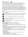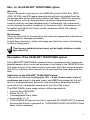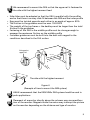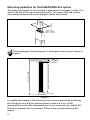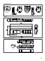
1
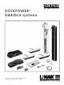
DESKPOWER
DB4/DL4 systems
TM
To learn more about LINAK, please visit:
W W W. L I N A K . C O M
2
Contents
Preface .................................................................................................................................................................. 4
Safety instructions ............................................................................................................................................... 5
Before installation, reinstallation or troubleshooting ...................................................................................... 5
Before start-up ..................................................................................................................................................... 5
During operation ................................................................................................................................................. 5
Repairs .................................................................................................................................................................. 6
Manufacturer’s declaration ................................................................................................................................. 6
Misc. on the DESKLINE® DESKPOWER system.................................................................................................... 7
Warranty ............................................................................................................................................................... 7
Maintenance......................................................................................................................................................... 7
The DESKLINE® DESKPOWER system ................................................................................................................. 7
Mounting guidelines for the DESKPOWER DB4 system ............................................................................. 8
Mounting guidelines for the DESKPOWER DL4 system ............................................................................ 10
Mounting guidelines CBD4/CBD5 .............................................................................................................. 12
Operation of the DPXX .............................................................................................................................. 13
Operation of the DP1C ............................................................................................................................... 14
Operation of the DPT ................................................................................................................................. 16
Mounting of the DPT .................................................................................................................................. 18
Operation of the WDPL .............................................................................................................................. 19
Calibrating the WDPL ................................................................................................................................. 20
Electrical connection of the DB4/DL4 system ............................................................................................ 24
Initialisation of the DESKPOWER DB4/DL4 parallel systems..................................................................... 25
Anti-CollisionTM ............................................................................................................................................ 26
Disposal of LINAK’s products ............................................................................................................................ 27
Labels ................................................................................................................................................................. 29
Drawing appendix ............................................................................................................................................. 30
Addresses ........................................................................................................................................................... 36
3
Preface
We are delighted that you have chosen a product from LINAK A/S. LINAK
systems are high-tech products based on many years of experience in the
manufacture and development of actuators, electronic control boxes,
controls, and chargers. We are also constantly improving our products to
meet customer requirements.
This User Manual will tell you how to install, use, and maintain your LINAK
DESKLINE® products.
We are sure that the DESKLINE products will give you many years of
problem-free operation. Before our products leave the factory they undergo
full function and quality testing. Should you nevertheless experience
problems with your systems, you are always welcome to contact our service
departments or service centres.
LINAK subsidiaries and distributors all over the world have authorised
service centres, which are always ready to help you.
LINAK provides a warranty on all its products. This warranty, however, is
subject to correct use in accordance with the specifications, maintenance
being done correctly, and any repairs being carried out at a service centre,
which is authorised to repair LINAK products.
Changes in installation and use of LINAK systems can affect their operation
and durability. Changes must therefore only be made by agreement with
LINAK A/S and are made at your own risk.
LINAK A/S
4
Safety instructions
Safe use of the system is possible only when the operating instructions are
read completely and the instructions contained are strictly observed.
Failure to comply with instructions marked with the ”NOTE” symbol may
result in serious damage to the system or one of its components.
Persons who do not have the necessary experience or knowledge of the
product/products must not use the product/ products. Besides, persons with
reduced physical or mental abilities must not use the product/products, unless
they are under surveillance or they have been thoroughly instructed in the
use of the apparatus by a person who is responsible for the safety of these
persons.
Moreover, children must be under surveillance to ensure that they do not
play with the product.
It is important for everyone who is to connect, install or use the systems
to have the necessary information and access to this User Manual.
If there is visible damage on the product it must not be installed.
The appliance is not intended for use by young children or infirm
persons without supervision.
Young children should be supervised to ensure that they do not play
with the appliance.
Before installation, reinstallation, or troubleshooting
• Stop the DB4/DL4
• Switch off the power supply and pull out the mains plug.
• Relieve the DB4/DL4 of any loads, which may be released during the work.
Before start-up:
• Make sure that the system has been installed as instructed in this User Manual.
• Make sure that the voltage at the control box is correct before the system
is connected to the mains.
• System connection. The individual parts must be connected before the
control box is connected to the mains. See the User Manual for LINAK
actuators, if necessary.
During operation:
• If the control box makes unusual noises or smells switch off the mains
voltage immediately.
• Take care that the cables are not damaged.
• Unplug the mains cable on mobile equipment before it is moved.
5
Repairs
In order to avoid the risk of malfunction, all DESKLINE® repairs must only be
carried out by authorised LINAK workshops or repairers, as special tools must
be used and special gaskets must be fitted. Lifting units under warranty must
also be returned to authorised LINAK workshops.
Warning!
If any of the DESKLINE ® products are opened, there will be a risk of
subsequent malfunction.
Warning!
The DESKLINE ® systems do not withstand cutting oil.
Manufacturer's declaration
Implementation with regard to the Community
legislation on machinery
Directive 98/37/EC attachment II B:
LINAK A/S, subsidiaries or representatives,
(see back cover)
prohibit that actuators are put into service
until the machinery into which the actuator is to be
incorporated has been declared in conformity with
the provisions of all relevant Directives.
Bent Jensen
LINAK A/S
6
Misc. on the DESKLINE® DESKPOWER system
Warranty
There is 36 months’ warranty on the DESKLINE products DB4, DL4, CBD4,
CBD5, DP, DPA, and DPB against manufacturing faults calculated from the
production date of the individual products (see label). LINAK A/S’ warranty
is only valid in so far as the equipment has been used and maintained
correctly and has not been tampered with. Furthermore, the system must
not be exposed to violent treatment. In the event of this, the warranty will
be ineffective/invalid. For further details, please see LINAK A/S ordinary
conditions of sale.
Maintenance
Clean dust and dirt on the outside of the system at appropriate intervals and
inspect them for damage and breaks.
Inspect the connections, cables, and plugs and check for correct functioning
as well as fixing points.
The cleaners and disinfectants must not be highly alkaline or acidic
(pH value 6-8).
Description of the DESKLINE ® DESKPOWER system
Each DESKLINE® DESKPOWER actuator/column is equipped with a motor and
parallel/memory drive is ensured by means of software in the CBD4/CBD5 that
also takes account of an oblique load on the desk. Soft start and stop are also
part of this software, which ensures a soft start and stop when adjusting the
desk.
Application of the DESKLINE ® DESKPOWER system:
Irrespective of the load the duty cycle 10% ~ 6 min./ hour or max. 2 min. at
continuous use stated in the data sheets, must NOT be exceeded as this will
result in a superheating of the motor and control box. Exceeding the duty
cycle will result in a dramatic reduction of the life of the system.
The DESKPOWER system range contains following products:
• 1 control box CBD4/CBD5
• DB4 or DL4 (1 - 4)
• 1 exchangeable mains cable
• motor cables (1 - 4)
• 1 DP1U/DPF1M (if memory function is required) DP1C/WDPL/DPT (if memory
function and display is required) or 1 DPA/DPB/DP1K/DP1L/DP1V/DPFK (Desk
Panel without memory)
7
Mounting guidelines for the DESKPOWER DB4 system
For detailed information on how to mount the DB4, please contact LINAK.
Must be fixed in the top plate
Sliding point in the inner profile
Sliding point in the inner profile
Must be connected to
the middle profil
Must be fixed in the bottom plate
Figure 3
(DB4 fixing points)
The guidances must be secured against rotation.
The DB4 must not be activated when it is not mounted in guidance due
to the risk of squeezing.
8
We recommend to mount the DB4 so that the upper rail is fastened to
the side with the highest moment load.
• Side slides must be adapted so that the DB4 is parallel with the profiles
and so that there is an easy slide fit between the DB4 and the inner profile
• Bugs must be twisted opposite each other in an angle of approx. 80%
• The friction in the guidance must be max. 150-200 N
• The weight of the top frame + the desktop must be larger than the total
friction in the guidances
• Fastening of the DB4 in the middle profile must be strong enough to
manage the maximum friction on the middle profile
• Customer guidances must be built into the desk with regard to the
conditions described in the DL4 section
Fixing point
upper rail
The side with the highest moment
Figure 4
(Example of how to mount the DB4 system)
LINAK recommends that the DESKLINE ® DB4 system should be used in
push applications.
Placement of a monitor directly above the columns may cause malfunction of the monitor. Magnets inside the motor may interrupt the picture
on the monitor depending on the distance and type of monitor.
9
Mounting guidelines for the DESKPOWER DL4 system
The mounting bracket for the crossbar is mounted on the largest profile. The
cable is led out at the top of the small profile. This means that the column
must always be mounted with the largest profile downwards.
B
Screw length
Min. B + 10 mm
Max. B + 15 mm
Figure 1
The mounting of the bottom part is analogue to the top part shown in
Figure 1.
Height of the DL4 in the lowest position
Min. desk height
Table top
Absorbing
material
Floor level
Figure 2
A suitable desk height in the lowest position can be obtained by mounting
the lifting unit on a 6-8 mm bottom plate by means of 4 pcs. of M6
countersinked screws. We recommend you to use screws of min. quality 8.8.
The thrust moment must not exceed 10 Nm in the top and bottom plate
thread.
10
Figure 3
(Example of how to mount a 2 parallel DESKLINE ® DESKPOWER DB4/DL4 system)
LINAK recommends that the DESKLINE® DESKPOWER DL4 system should
be used in push applications.
Placement of a monitor directly above the motor may cause malfunction
of the monitor. Magnets inside the motor may interrupt the picture on
the monitor depending on the distance and type of monitor.
If this is the case the problem may be solved by placing an iron plate/tube
or another magnetic material, somewhat larger than the profile between
the motor and the tabletop.
The mounting screws on the DP, DPA, or DPB must be fastened with a
max. torque of 1 Nm.
The DL4 is mounted with a conical dovetail bracket (female). On the crossbar the counterpart of this bracket must be mounted (male). This bracket
can be ordered at LINAK.
When mounting the bracket onto the crossbar you must be careful to
mount the brackets perpendicular to the crossbar and that the centre distance of the bracket fits exactly with the centre distance of the legs in the
top frame bore of the desk (oblong holes in the top frame give adjustable
centre distance).
When the crossbar is mounted onto the legs it must be tightly fixed with a
plastic hammer to obtain the maximum stability.
The bracket has to be fully welded in both ends not through the holes in
the bracket (the bracket will bend). Do not mount extra brackets in a way
that deforms the profiles.
When designing the desk/top frame and placing the control box you have
to choose a design/a placement that ensures there is no risk of squeezing
at the crossbar.
11
Mounting guidelines CBD4/CBD5
The control box is to be fastened with 4 screws (3 screws for CBD5) with a
head diameter between ø 8 and ø 10 mm. Out of regard for the tension
surface ø 10 mm is preferable. See drawing appendix for placing of mounting
holes and the space the CBD takes up.
CBD4 - Control box
CBD5 - Control box
The CBD must not be packed in heat insulating material, but must be placed
so that it can emit waste heat into the surroundings. There are no ventilation
holes to consider, the CBD emits heat through the surface.
The plug must be visable when the CBD is mounted so that the supply to the
CBD can be disconnected at replacement, if any.
The mounting screws on the control box must be fastened with a max. torque
of 1 Nm.
The mounting surface to which the control box is attached should have a
surface evenness of better than ± 0.5 mm.
12
Operation of the DP
The Desk Panel is used to operate the DESKLINE®
system. The DP is available in a number of
versions DPA/DPB/DP1K/DP1L/DP1U/DP1V/
DPF1K for single/parallel drive without memory
and DP1U/DPF1M for single/parallel drive with
memory (3 memory positions). The two arrow
buttons are used for single/ parallel drive and the
last four buttons for memory drive.
DPA - Desk Panel
DPB - Desk Panel
1
2
3
S
Desk up
Desk down
Memory 1
Memory 2
DP1K - Desk Panel
Memory 3
Store memory
DP-025
DP1L - Desk Panel
Single/parallel drive
The arrow buttons start the DL4/DB4. The
function is only activated when holding down
the button.
1
2
3
S
DP1U - Desk Panel
Memory drive 1 2 3
Memory 1, 2, and 3 start a memory drive,
the channel(s) drive to a preprogrammed
position.
Store memory S
Push S
Within two sec. push either 1 , 2 , or 3
DP-025
DP1V - Desk Panel
DPF1K - Desk Panel
DPF1M - Desk Panel
13
Operation of the DP1C
The DP1C cannot be used on the CBD4 with mains cut-off.
Description
The DP1C is equipped with a display and memory and is compatible with the
CBD4 (Advanced, software 077402 ver. 1.66 or later). The DP1 is only available
as a 1-channel version for operation of the parallel channels up and down.
The actual height of the desk is shown in the display. The display is of the LED
type with a yellow light and 10 mm high digits.
Desk up
Desk down
S
Store memory
1
Memory 1
2
Memory 2
3
Memory 3
Normal operation:
To run the desk up or down, press the UP or DOWN button, and keep it pressed
until the desk reaches the desired height. The display will count up or down
while running, and after stop it will continually show the current height of the
desk.
Changing between cm and inches:
Keep the S button pressed for approx. 4 sec. and the reading will change
from the current setting. The default setting depends on the type chosen.
Store a memory position:
When pressing the “store” button the display will flash “S” for 3 sec. Within
the 3 sec. press memory button 1, 2 or 3. The display will acknowledge by showing S1, S2, or S3 for 1 sec. To abort a store sequence press the UP or DOWN button while the “S” is flashing, or wait the 3 sec. until the display automatically
returns to show the height of the desk.
Drive to a stored position:
Version with “GO-memory”
Press memory button 1, 2, or 3. The display will flash “GO1”, “GO2” or “GO3”
for 3 sec. Within the 3 sec. press the UP or DOWN button and keep it pressed
until the desk stops in the stored position. Both the Up and the Down button will activate memory drive. Although e.g. the memory position is higher
than the actual height, it will drive upwards when you press the Down button.
While running to a memory position the display will show GO1, GO2 or GO3,
and when it stops in the stored position, the height of the desk will be shown.
Releasing the UP or DOWN button will abort the memory drive. The display will
show the height of the desk.
Version with “standard memory”
Press memory button 1, 2, or 3 and the system will start driving to the wanted
14
memory position. Keep the button pressed until the position is reached. The
display will show the actual height during the memory run.
Adjust the display to show the correct height:
It may be necessary to adjust the display due to different thicknesses of desktops
etc, when the DP is delivered from the factory. The DP will show 68 cm or 24.5
inches (default setting) height of the desk. At the same time press the “Store”
button and step UP or DOWN, until the display shows the correct height.
Adjusting the light intensity of the LED display
Possible light settings are: 0= off, 25 = 25%, 50 = 50%, 75 = 75%, 100 = 100%.
Adjustment procedure
Press the “1” button and at the same time either “desk up” or “desk down” this
will adjust the light intensity. Initial press will show the current setting. Keep
the “1” button pressed during the whole sequence while adjusting up or down.
Keep a button pressed for more than 800 msec then the button will auto repeat
every 100 msec. Releasing all buttons stores the new setting.
Adjusting the light timeout
Possible light timeouts are: 0-15 sec and off
Adjustment procedure
Press the “3” button and at the same time either “desk up” or “desk down”
this will adjust the light timeout. Initial press will show the current setting. Keep
the “3” button pressed during the whole sequence while adjusting up or down.
Keep a button pressed for more than 800 msec then the button will auto repeat
every 100 msec. Releasing all buttons stores the new setting.
Errors
Below please find the possible errors which can be displayed. The errors will only
be displayed when a button is pressed. The display blinks while showing the error. E16 overrules any other error as the detection is registered only in the display
and no message is sent to the control box.
Diagnostic errors
The CBD4 (version 1.86 or later) can send up to 6 different diagnostic error codes
at the same time. The diagnostic error codes will overrule error states (except
E16). Diagnostic errors will only appear as long as the button is pressed. The display will blink EXX and will toggle through the diagnostic errors and send them
to the LINBUS in the CBD. For detailed error description and codes please see the
appropriate CBD software description.
(Only working with the DP1C from production date 1 february 2006 and onward)
Error no.
Description
E01
The desk has an unknown position and needs to be initialised.
E02
Overload upwards has occurred.
E03
Overload downwards has occurred.
E16
Illegal keys pressed.
15
Operation of the DPT
For safety reasons the DPT has a locking function.
If the DPT is locked, only a bar is lightning in the display. To unlock the
control press ¨S¨ for 1 sec. When the DPT is unlocked, the height will be
shown in the display. Now the DPT is active for 2.5 seconds. When pressing one of the keys you can do your adjustment. Hereafter the DPT will
be active for 5 seconds but when there are no activations made within
the mentioned time slot, the DPT will go in to locking mode again. Also if
you press ¨S¨ for unlocking too long, the DPT will unlock but immediately
lock again.
The Touch Desk Panel is used to operate the DESKLINE® systems. The DPT is
divided into parallel and memory drive. The two arrow buttons are used for
parallel drive and the last four buttons for memory drive.
Desk up
Desk down
S
Store memory
1
Memory 1
2
Memory 2
3
Memory 3
Normal operation:
To run the desk up or down, press the or button, and keep it pressed until
the desk reaches the desired height. The display will count the height as the
table is moving and will continually show the height of the desk after stopping.
Storing a memory position:
Touch the “S” button the display will flash “S” for 3 sec. While the ¨S¨ is displayed,
touch the memory button 1, 2 or 3. The display will acknowledge by showing S1,
S2 or S3 for 1 sec.
To abort a store sequence press the or button while the “S” is flashing, or wait
the 3 seconds until the display automatically returns to show the height of the
desk.
Drive to a stored position:
Press memory button 1, 2 or 3 and the system will start driving to the desired
memory position. Keep the button activated until the position is reached. The
display will count the height as it is driving to the memory position.
Customizing the DPT digital display
Adjust the display to show the correct height:
The DPT will show 68 cm or 24.5 inches as the height of the desk as the default
setting. It may be necessary to adjust the displayed height due to different thicknesses of desktops etc. when the DPT is delivered from the factory. To adjust
the display touch the ¨S¨ button and the or button at the same time until the
display shows the actual height of the desk.
16
Changing between cm and inches:
Touch the ¨S¨ button for approximately 4 seconds and the unit of measurement
will change on the display. The default setting depends on the type chosen.
Error Codes
The DPT has capability of displaying error codes for diagnostic feedback. Below
are possible feedback errors which can be displayed by the DPT. The error codes
will only be displayed when a button is touched in unlocked mode. The display
will blink while showing the error. E16 overrules any other error since the
detection is registered only in the display and no message is sent to the control
box. For detailed error description and codes please see the appropriate CBD
software description.
Error no.
Description
E01
The desk has an unknown position and needs to be initialised.
E02
Overload in upwards direction has occurred.
E03
Overload in downwards direction has occurred.
E16
Illegal keys are pressed.
17
Mounting of the DP1T:
The hole in the table top has to be made according to the drawing. The DPT
is mounted in the hole and the two screws on the back side are fastened with
a maximum torque of 40Ncm. If you do not have a torque screw driver please
tighten gently and not more until you can feel a slight resistance. Do not use
electrical tool!!
Please note:
1. Mounting the DPT into the table top should be done at the end user,
so the product won’t be exposed to any stress which can destroy the
product, when transported.
2. For countersink versions the technician must ensure that the acrylic
plate is not put under pressure which will push the acrylic plate out
of place.
3. The screws which are delivered with the product must be used. If they
have gone lost there shouldn’t be chosen new screws which are longer
than 12 mm, otherwise top and bottom will disconnect.
4. If the product has visible damages it shouldn’t be mounted.
5. The product is IP30; the customers can be sure that fluids / dust will
not enter the product. The front it selves is closed by the acrylic plates
adhesive foil.
6. Cable release is specified for max. 5 kg
7. Remember to remove the protection foil.
Frame:
Countersink:
18
Operation of the WDPL
The batteries:
Wired WDPL: Install 3 x 1.5 V batteries
type AA. The batteries are
used as a backup of the clock
function if the CBD is
disconnected from the mains.
WDPL
-
+
+
Figure 9
When the batteries are mounted the display will show the clock function in hh:
mm. The clock has to be adjusted. See adjusting the clock on page 21.
Low battery:
Change batteries at weak contrast in the display or when the display shows
strange symbols/misinformation.
This does not influence the function of the WDPL - it is exclusively a sign that
the batteries are to be replaced.
The WDPL will also work without batteries because it will be powered by the
control box.
The WDPL will also work on a CBD4/CBD5 with mains cutoff. The clock will only
be shown if you have battery backup.
The cable from the WDPL is connected to the control box under your table:
WDPL
Control box
WDPL fitting
for desk
Figure 11
Display layout - WDPL:
19
Calibrating the WDPL
For the WDPL to function correctly you have to calibrate your system.
This has to be done before using the WDPL. You only have to do this once.
Action:
Display view:
1. Switch between [cm] and [inch]. Press and hold
Store
and then press
. "
User
Desk I User I
Desk I
User I
Desk I
User I
2. Measure the height from desk to floor.
If only one desk is connected, - go to point 4.
3. Press Desk and then press
l
,
ll
or
lll
to select desk.
If only one desk is connected it is not possible to select Desk ll or lll.
Store
and then press
v
4. Press and hold
or
v
to adjust the
height in the display.
Example:
The display will switch from e.g. 68 to 69, 70, 71 etc. when
is pressed and held and then
Store
v
Store
and e.g. 68 to 67, 66 etc. when
pressed.
is pressed.
is pressed and held and then
v
is
Store
5. When the wanted height is shown in the display press and hold
Store
Desk I
User I
and then Desk . The reference height of the desk will now be stored in the
control box.
When the reference height is stored the digits will be switched off for 1 sec.
and back on again.
If the buttons are not activated for 15 sec. the clock function will appear in
the display.
It is not necessary to repeat calibration when changing batteries.
20
Adjusting the clock
Example:
Action:
Display view:
1. Press the “clock button” using a ball pen.
24hr mode (European time mode) is default - can be changed to 12hr mode
(US time mode)
Flashing
Changing time mode:
v
Press
or
v
AM
PM
Flashing
(Press the “clock button” again to confirm “time mode” using a ball pen)
AM
..
hh is flashing
v
2. Press
or
v
to adjust “hh”
PM
..
Switches to PM if hh > 11
3. Press the “clock button” again to confirm “hh”.
PM
..
mm is flashing
v
4. Press
or
v
to adjust “mm”
PM
..
5. Press the clock button again to confirm “mm”
The clock is now activated.
21
Store a memory position
3 users can store 3 memory posistions each. The connected desks (max. 3) are
to be adjusted individually - one at a time.
Quick setup:
On the back of the WDPL you will find a quick guide for storing a memory
position.
Example:
Action:
Display view:
If only one desk is connected, - go to point 4.
1. Press Desk
l
3. Press
User
4. Press
l
,
ll
Desk I User I
lll
or
until the wanted desk is shown in the display.
➙
2. Press
Flashing
ll
lll
or
until the wanted user is shown in the display
Desk I User I
➙
,
Flashing
v
5. Press
or
v
until the wanted height is obtained.
Desk I User I
6. Press
Store
and then
l
,
ll
or
lll
Store
Desk I User I Position II
The position is now stored in the control box.
To store a new memory position on the same desk go through points 3 to 6
again.
If the buttons are not activated for 15 sec. the clock function will appear in
the display.
22
Switch to a stored memory position
Quick setup:
On the back of the WDPL you will find a quick guide for storing a memory
position.
Example:
Action:
1. Press
Display view:
User
➙
Desk I User III
Flashing
2. Press
l
,
3. Press and hold
ll
l
or
lll
,
ll
until the wanted user is shown in the display
or
lll
until all desks have reached their
memory position.
Desk I User III Position I
The display will show the height of the moving desk for about 15. sec.
Position l is flashing digits counting from
117 to 88. When the desk
has reached the new height
position l it will stop flashing.
If the buttons are not activated for 15 sec. the clock function will appear in
the display.
Troubleshooting:
At errors the error code appears from the display - The “error” segment
flashes (1 Hz).
E-01
Position lost
Initialize
E-02
E-03
23
Electrical connection of the DB4/DL4 system:
The DESKPOWER system is to be connected as shown on figure 7. Each DB4/
DL4 is to be connected to the sockets on the control box by means of the
motor cables, which have an 6-pin plug in each end.
Finally the mains cable is to be mounted and power switched on.
Please note that the control box must only be connected to the voltage
stated on the label.
CBD4/CBD5 with earth
The CBD4/CBD5 earth cable to be mounted on the desk construction (typically
the top frame)in a way that ensures good electrical contact. The function of
the earth cable is to earth the desk and ground static electricity. The earth
connection does not protect other electrical products.
CBD4/CBD5 with mains cutoff
If the power cable is damaged it has to be replaced by an authorised
LINAK service centre to avoid any danger.
Hook for cable relief
Mains cable
The cable can both be placed to
the left or right on the DL4
Control/
dongle DL/DB
Figure 7
24
Initialisation of the DESKLINE DB4/DL4 parallel systems
The DESKPOWER system is initialised by pressing the down button once or
twice and holding it down until the DB4/DL4 runs into end stop. It will then
automatically run approx. 5 mm out again and hereafter slowly run in again.
Only release the down button when the movement has completely stopped.
If the button is released before the sequence is complete then the
initialisation is interuppted and must be started again from the beginning.
It is sometimes necessary to press the down button twice to start the
initialisation, this is because the system can be in different modes when the
initialisation starts. There will be a 1.25 sec. delay. If an error situation occurs at
the end stop positions or DB4/DL4 are changed to another stroke length, then
CBD4/CBD5 has to be initialised again.
The first two times the system runs into the outward end stop, it will
automatically run approx. 3 mm back in inward direction.
Approx. 5 mm
The CBD5 can control the DB4 and the DL4 in 2 parallel and 3 parallel while
the CBD4 can control the DB4 and the DL4 in 2, 3, and 4 parallel so that the
desk is always kept horisontal.
25
Anti-Collision™ (only for DL4, DL6, DL9, and DL11)
The function anti-collision is a new option for the standard CBD4/CBD5
advanced/ control box software version 1.66 and later. A system with anticollision can limit material damages on a desk if a collision with a solid
object should occur.
Enabling the anti-collision
To enable the anti-collision function a little plug called a dongle must be
mounted in one of the 2 control ports. The function is only active when
the dongle is mounted. –If you remove the dongle again you disable the
function.
Method of operation
When the DL/DB’s are running the CBD4/CBD5 monitors the current
consumption on each channel using a special algorithm. If the current
consumption on one channel is increased more than a predefined slope a
collision is assumed and all channels are stopped immediately and all DL/
DB’s will start to run in the opposite direction (approx. 50 mm). This return
drive is done automatically and continues with or without any control key
pressed (for max. 2.5 sec.).
The anti-collision sensitivity is different in up and downward direction.
Upwards the force is approx. 20 kg. Downwards the load will be approx. 40
kg + the load on the DL/DB (the desk + what is on top of the desk). The 40
kg are needed to activate the anti-collision function.
Situations where the anti-collision does not work
There are situations where the anti-collision will not be activated. These
situations are:
• If the collision happens during the initialisation phase
• If the collision happens within the first 1000 msec or after the control
button has been released
• If the collision happens between the floor and the table and the load on
the desk + the weight of the legs are lower than 40 kg
• If the collision happens over too long time, e.g. if the collision is with a
soft object
26
Disposal of LINAK’s products
As LINAK’s customers often ask us how our products can be disposed of or
scrapped we have prepared this guidance that enables a classifi cation to
different waste fractions for recycling or combustion.
Guidance
We recommend that our products be disassembled as much as possible and
divided into different waste groups for recycling or combustion.
For example, waste can be sorted into metals, plastics, cable scrap,
combustible material, and recoverable resources.
Some of these main groups can be further divided into subgroups; e.g.
metal can be divided into steel/aluminium/copper and plastic can be divided
into ABS/PA/PE/PP.
As an example, the table below breaks down the different components in
LINAK products to various recycling groups:
Product
Components
Recycling group
Columns/
Actuator :
Spindle and motor
Plastic housing
Cable
PCB boards
Scrap
Plastic recycling or combustion
Cable scrap or combustion
Electronics scrap
Control Box :
PCB boards
Plastic housing
Cable
Transformer
Electronics scrap
Plastic recycling or combustion
Cable scrap or combustion
Metal scrap
Handset/
Control :
Plastic housing
Cable
PCB board
Plastic recycling or combustion
Cable scrap or combustion
Electronics scrap
By now almost all our casted plastic parts are supplied with an interior code
for plastic type and fibre contents, if any.
Main groups of disposal
Product main
groups
Metal
Scrap
Cable
scrap
Electronics
scrap
Plastic recycling Comments
or combustin
DB4
X
X
X
X
DL4
X
X
X
X
CBD4/CBD5
X
X
X
X
DPXX
X
X
X
WDPL
X
X
X
27
Disposal of batteries.
"Details regarding safe disposal of used and leaking batteries:
Batteries should be disposed in accordance with appropriate federal, state
and local regulations. LINAK recommends that used or leaking batteries are
disposed through local recycling system. Please do not throw used or leaking
batteries in normal household waste or in nature. This will cause damage to
the enviroment.
How to deal with leaking batteries.
Leaking batteries should be disposed as described above.
If leaking batteries are discovered in the product the batteries must be
removed at once to minimise damage to the product. If leaking batteries are
left in the product it might become defect.
It is recommended to use plastic gloves when handeling leaking batteries.
The contents of a leaking batteries can cause chemical burns and respiratory
irritation.
If exposed to the contents of a leaking battery, please wash with soap and
water. If irritation persists, please seek medical attention. In case of eye
contact, please flush eyes thoroughly with water for 15 minutes and seek
medical attention."
28
Label for CBD4
Label for DB4
Label for DP
Label for CBD5
Label for DPA
The label is printed
directly on the DPA
-B
06
AK 03
DP 06
02
Label for DPB
The label is printed
directly on the DPB
DPBK06
P.O.: 299218
Label for DL4
DPBK06
P.O.: 299218
Label for DPF
Label for WDPL
Label for DPT
29
DRAWING APPENDIX
DESKLINE® DESKPOWER DB4/DL4 System:
DL4
85.2 (CENTER R6.4)
M6x4
109.2 ± 0.3
80 ± 0.2
M6x4
57.8 ± 0.3
28 ± 0.2
560 ± 2
A
R241.48
22 ± 0.2
R246.33
DETAIL
B
98 ± 0.3
2
R1
DETAIL
46.6 ± 0.3
26.18 (CENTER R6.4)
R6
.4
87 ± 0.2
552 ± 0.5
30
SEE DETAIL B
SEE DETAIL A
1235
Standard cable length = Approx. 50 mm
Stroke = 675 ± 2 mm
DB4
49.6
54.2
30
Ø86
48
542
DPA
.4
Ø4
53.4
13
24
28
8
49.6
55.5
25.5
33.5
DPB
DP Desk Panel
31
DP1C Desk Panel
Ø4.5
Ø8.5
25.5
42
161
112
DP1U Desk Panel
1
DPF1K Desk Panel
DPF1M Desk Panel
32
2
3
S
84
DPT Desk Panel
WDPL
9.6
WDPL fitting for desk:
110
49.5
ø5
25.7
179.9
33
CBD4
278
247
80
119
100.6
4
3
2
1
B
B
5.5
AC
5.5
34
51
62
CBD5
LINAK APPLICATION POLICY
The purpose of the application policy is to define areas of responsibilities in relation
to applying a LINAK product defined as hardware, software, technical advice, etc.
related to an existing or new customer application.
LINAK products as defined above are applicable for a wide range of applications
within the Medical, Furniture, Desk and Industry areas. Yet, LINAK cannot know all
the conditions under which LINAK products will be installed, used, and operated, as
each individual application is unique.
The suitability and functionality of the LINAK product and its performance under
varying conditions (application, vibration, load, humidity, temperature, frequency,
etc.) can only be verified by testing, and shall ultimately be the responsibility of the
LINAK customer using any LINAK product.
LINAK shall be responsible solely that the LINAK products comply with the
specifications set out by LINAK and it shall be the responsibility of the LINAK customer
to ensure that the specific LINAK product can be used for the application in question.
35
FACTORIES
CHINA
LINAK (Shenzhen) Actuator Systems, Ltd.
Phone: +86 755 8610 6656 . Fax: +86 755 8610 6990
E-mail: [email protected] . www.linak.cn
NORWAY
LINAK Norge AS
Phone: +47 32 82 90 90 . Fax: +47 32 82 90 98
E-mail: [email protected] . www.linak.no
IRAN
Bod Inc.
Phone: +98 21 88527255 . Fax: +98 21 88514037
E-mail: [email protected] . www.bod.ir
DENMARK
LINAK A/S . Group Headquarters Guderup
Phone: +45 73 15 15 15 . Fax: +45 74 45 80 48
Fax (Sales): +45 73 15 16 13
E-mail: [email protected] . www.linak.com
POLAND
LINAK Polska
Phone: +48 (22) 500 28 74 . Fax: +48 (22) 500 28 75
E-mail: [email protected] . www.linak.pl
MEXICO
ILSA S.A. de C.V.
Phone: +[52] (55) 5388-3960 . Fax: +[52] (55) 5388-3966
E-mail: [email protected] . www.ilsamexico.com
SPAIN
LINAK Actuadores S.L.
Phone: +34 93 588 27 77 . Fax: +34 93 588 27 85
E-mail: [email protected] . www.linak.es
RUSSIAN FEDERATION
000 FAM
Phone: +7 812 3319333 . Fax: +7 812 3271454
E-mail: [email protected] . www.fam-drive.ru
SWEDEN
LINAK Scandinavia AB
Phone: +46 8 732 20 00 . Fax: +46 8 732 20 50
E-mail: [email protected] . www.linak.se
SINGAPORE
SERVO DYNAMICS PTE. Ltd.
Phone: +65 6844 0288 . Fax: +65 6844 0070
E-mail: [email protected] . www.servo.com.sg
SWITZERLAND
LINAK AG
Phone: +41 43 388 31 88 . Fax: +41 43 388 31 87
E-mail: [email protected] . www.linak.ch
SOUTH AFRICA
Industrial Specialised Applications CC
Phone: +27 11 312 2292 or +27 11 2077600
Fax: +27 11 315 6999
www.stabilus.com
SUBSIDIARIES
AUSTRALIA
LINAK Australia Pty. Ltd
Phone: +61 3 8796 9777 . Fax: +61 3 8796 9778
E-mail: [email protected] . www.linak.com.au
AUSTRIA
LINAK GmbH
Phone: +43 2746 21036 . Fax: +43 2746 21044
www.linak.at
BELGIUM & LUXEMBOURG
LINAK Actuator-Systems NV/SA
Phone: +32 (0)9 230 01 09 . Fax: +32 (0)9 230 88 80
E-mail: [email protected] . www.linak.be
BRAZIL
LINAK do Brasil Comércio de Atuadores Ltda.
Phone: +55 (11) 6832-7070 . Fax: +55 (11) 6832-7060
E-mail: [email protected] . www.linak.com.br
CANADA
LINAK Canada Inc.
Phone: +1 905 821 7727 . Fax: +1 905 821 4281
E-mail: [email protected] . www.linak.ca
TAIWAN
LINAK A/S Taiwan Representative Office
Phone: +886 2 250 80296 . Fax: +886 2 2508 3604
E-mail: [email protected] . www.linak-asia.com
SOUTH KOREA
UNITEK ENG.
Phone: +82 2 567 0888 . Fax: +82 2 3453 1177
E-mail: [email protected] . www.unitekeng.co.kr
TURKEY
LINAK A/S Turkey Representative Office
Phone: +90 312 4726338-59 . Fax: +90 312 4726635
E-mail: [email protected] . www.linak.com.tr
UNITED KINGDOM
LINAK UK Limited
Phone: +44(0)121 544 2211 . Fax: +44(0)121 544 2552
E-mail: [email protected] . www.linak.co.uk
DISTRIBUTORS
ARGENTINA
NOVOTEC ARGENTINA SRL
Phone: +[54] (11) 4303-8900/89 . Fax: +[54] (11) 4032-0184
E-mail: [email protected]
www.novotecargentina.com
CZECH REPUBLIC
LINAK C&S S.R.O.
Phone: +420581741814 . Fax: +420581702452
E-mail: [email protected] . www.linak.cz
COLOMBIA
MEM Ltda
Phone: +[57] (1) 334-7666 . Fax: +[57] (1) 282-1684
E-mail: [email protected]
www.memltda.com.co
DENMARK
LINAK DANMARK A/S
Phone: +45 86 80 36 11 . Fax: +45 86 82 90 51
E-mail: [email protected] . www.linak.dk
INDONESIA
PT. HIMALAYA EVEREST JAYA
Phone: +6 221 544 8956/65 . Fax: +6 221 619 4658/1925
E-mail: [email protected]
UNITED ARAB EMIRATES
Mechatronics
Phone.: +971 4 267 4311 . Fax: +971 4 267 4312
E-mail: [email protected]
www.mechatronics.ae
For contact details on other countries please visit
www.linak.com or contact:
LINAK INTERNATIONAL
Fax: +45 74 45 90 10
E-mail: [email protected] . www.linak.com
FINLAND
LINAK OY
Phone: +358 10 841 8700 . Fax: +358 10 841 8729
E-mail: [email protected] . www.linak.fi
FRANCE
LINAK FRANCE S.A.R.L
Phone: +33 (0)2 4136 3434 . Fax: +33 (0)2 4136 3500
E-mail: [email protected] . www.linak.fr
GERMANY
LINAK GmbH
Phone: +49 6043 9655 0 . Fax: +49 6043 9655 60
E-mail: [email protected] . www.linak.de
INDIA
LINAK A/S India Liaison Office
Phone: +91 80 2299 6533 . Fax: +91 80 2224 3863
E-mail: [email protected] . www.linak.in
IRELAND
LINAK UK Limited
Phone: +44(0)121 544 2211 . Fax: +44(0)121 544 2552
E-mail: [email protected] . www.linak.co.uk
ITALY
LINAK ITALIA S.r.l.
Phone: +39 02 48 46 33 66 . Fax: +39 02 48 46 82 52
E-mail: [email protected] . www.linak.it
JAPAN
LINAK K.K.
Phone: +81 45 533 0802 . Fax: +81 45 533 0803
E-mail: [email protected] . www.linak.jp
MALAYSIA
LINAK A/S Asian Representative Office
Phone: +60 4 210 6500 . Fax: +60 4 226 8901
E-mail: [email protected] . www.linak-asia.com
NETHERLANDS
LINAK Actuator-Systems B.V.
Phone: +31 76 5 42 44 40 . Fax: +31 76 5 42 61 10
E-mail: [email protected] . www.linak.nl
NEW ZEALAND
LINAK New Zealand Ltd.
Phone: +64 9580 2071 . Fax: +64 9580 2072
E-mail: [email protected] . www.linak.co.nz
The user is responsible for determining the suitability of LINAK
products for a specific application.
LINAK A/S takes great care in providing accurate and up-todate information on its products. However, due to continuing
developments in order to improve its products, LINAK products
are subject to frequent modifications and changes without prior
notice. Therefore, LINAK cannot guarantee the correct and actual
status of said information on its products. While LINAK uses its
best efforts to fulfil orders, LINAK cannot, for the same reasons
as mentioned above, guarantee the availability of any particular
product. Therefore, LINAK reserves the right to discontinue
the sale of any product displayed on its website or listed in its
catalogues or other written material drawn up by LINAK.
All sales are subject to the Standard Terms of Sale and Delivery
for LINAK A/S. For a copy hereof, please contact LINAK.
LINAK A/S reserve the right to make technical alterations
USA
LINAK U.S. Inc.
North and South American Headquarters
Phone: +1 502 253 5595 . Fax: +1 502 253 5596
E-mail: [email protected] . www.linak-us.com
Copyright © LINAK 2009.04 MA-M9-02-152-i
SLOVAKIA
LINAK Slovakia s.r.o.
Phone: +421 517563 414 . Fax: +421 517563 410
E-mail: [email protected] . www.linak.com