1
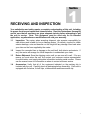
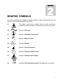
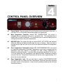
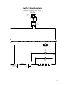
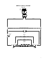
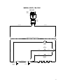
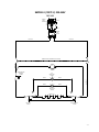
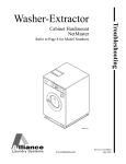
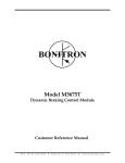
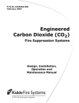
ECONOMY OVENS SMO1E SMO1E-2 SMO3E SMO3E-2 SMO5E SMO5E-2 PREVIOUSLY DESIGNATED AS 1321F 1321F-2 1325F 1325F-2 1327F 1327F-2 INSTALLATION AND OPERATION MANUAL Revised 12/2013 4861659 Sheldon Manufacturing Inc. P.O. Box 627 Cornelius, Oregon 97113 EMAIL: [email protected] INTERNET: http://www.Shellab.com/~Shellab 1-800-322-4897 (503) 640-3000 FAX (503) 640-1366 TABLE OF CONTENTS SECTION 1.0 RECEIVING AND INSPECTION SECTION 2.0 GRAPHIC SYMBOLS SECTION 3.0 INSTALLATION SECTION 4.0 CONTROL PANEL OVERVIEW SECTION 5.0 PRECAUTIONS SECTION 6.0 OPERATION SECTION 7.0 MAINTENANCE SECTION 8.0 TROUBLESHOOTING SECTION 9.0 PARTS LIST UNIT SPECIFICATIONS WIRE DIAGRAM This unit is a special purpose oven for professional, industrial or educational use where the preparation or testing of materials is done at approximately atmospheric pressure and no flammable volatile or combustible materials are being heated or placed near or on top of unit. This unit is not intended for hazardous or household locations or use. 2 1 Section RECEIVING AND INSPECTION Your satisfaction and safety require a complete understanding of this unit, including its proper function and operational characteristics. Read the instructions thoroughly and be sure that all operators are given adequate training before attempting to put the unit in service. Note: This equipment must be used only for its intended application; any alterations or modifications will void your warranty. 1.1 Inspection: The carrier, when accepting shipment, also accepts responsibility for safe delivery and is liable for loss or damage claims. On delivery, inspect for visible exterior damage, note and describe on the freight bill any damage found and enter your claim on the form supplied by the carrier. 1.2 Inspect for concealed loss or damage on the unit itself, both interior and exterior. If any, the carrier will arrange for official inspection to substantiate your claim. 1.3 Return Shipment: Save the shipping carton until you are sure all is well. If for any reason you must return the unit, first contact your customer service representative for authorization, and supply data plate information including serial number. Please see the manual cover for information on where to contact customer service. 1.4 Accessories: Verify that all of the equipment indicated on the packing slip is included with the unit. Carefully check all packaging before discarding. Each unit is equipped with 2 shelves, 8 shelf clips, a thermometer and thermometer clip. 3 2 Section GRAPHIC SYMBOLS Your oven is provided with a display of graphic symbols to help in identifying the use and function of the available adjustable components. 2.1 This symbol, when shown, indicates that you should consult your manual for further description or discussion of a control or user item. 2.2 Indicates "AC Power" 2.3 Indicates "Adjustable Temperature" 2.4 Indicates “Manual Control” 2.4 Indicates "Heating" 2.5 Indicates "Over Temperature" 2.6 Indicates “Protective Earth Ground ” 2.7 Indicates “Potential Shock Hazard” 2.8 Indicates “Unit should be recycled” (Not disposed of in land-fill) 4 3 Section INSTALLATION Local city, county, or other ordinances may govern the use of this equipment. If you have any questions about local requirements, please contact the appropriate local agency. Installation may be performed by the end user. Under normal circumstances this unit is intended for use indoors, at room temperatures between 5 and 40C, at no greater than 80% Relative Humidity ( at 25C) and with a supply voltage that does not vary by more than 10%. Customer service should be contacted for operating conditions outside of these limits. 3.1 Power: The power source must match the voltage, cycle, phase and ampere requirements listed on the data plate (located just above the power cord on the back side of the oven). The unit is intended for 50/60 HZ application. Make sure your power supply matches that shown on the data plate. VOLTAGE SHOULD NOT VARY MORE THAN 10% FROM THE DATA PLATE RATING. A separate circuit is recommended to preclude loss of product due to overloading or circuit failure. Note that the electrical supply to the unit must conform to all national and local electrical codes. 3.2 Location: When selecting a site for the oven, consider conditions that may affect performance, such as heat or cold from air vents, fast moving air currents, other ovens, autoclaves, direct sun, etc. Avoid high traffic areas that may reduce accessibility to the oven and allow at least 20cm between the unit and surrounding walls or partitions that might obstruct free airflow. 3.3 Lifting/Handling: These units are heavy and care should be taken to use appropriate lifting devices that are sufficiently rated for these loads. Units should only be lifted from their bottom surfaces. Doors, handles, and knobs are not adequate for lifting or stabilization. The unit should be completely restrained from tipping during lifting and transport. All moving parts, such as shelves and trays should be removed and doors need to be positively locked in the closed position during transfer to prevent shifting and damage. 3.4 Leveling: The unit must sit level and solidly. The oven is equipped with non-adjustable rubber feet to raise it off the counter and prevent sliding; however, the counter must be level to provide optimum working and safety conditions. 3.5 Cleaning: The oven was cleaned at the factory, but not sterilized. Remove all interior parts, including shelves and shelf clips. If assembled and clean the inside of the chamber thoroughly with a disinfectant that is appropriate for your application. DO NOT USE chlorine-based bleaches or abrasive cleaners, as they will damage the ovens interior surfaces. DO NOT USE spray cleaners that might leak through openings and cracks and get on electrical parts or that may contain solvents that will harm coatings. A regular periodic cleaning is recommended. WARNING: Never clean the unit with alcohol or flammable cleaners with the unit connected to the electrical supply. Always disconnect the unit from the electrical service when cleaning and assure all volatile or flammable cleaners are evaporated and dry before reattaching the unit to the power supply. 5 3.6 Shelves: Place shelves in the chamber at desired position. See Figure 1. Figure 1 6 4 Section CONTROL PANEL OVERVIEW 4.1 Power Switch: The main power I/O (on/off) switch controls all power to the oven. It must be in the I or ON position before any systems are operational. 4.2 Main Temperature Controller: Marked SET TEMPERATURE, this control is equipped with an adjustment knob and a graduated dial. The graduated dial is marked with 10 major increments. The increments can be used as index points for setting and returning to set point temperatures. 4.3 HEATING light: This green pilot light is marked HEAT ACTIVATED and indicates when the element has been activated and the oven is heating. When set point is reached the pilot light will cycle on and off as the elements maintain the temperature selected. 4.4 Over Temperature Thermostat: Marked SET OVERTEMPERATURE, this control is completely independent of the Main Temperature control and is equipped with an adjustment knob that requires a flat-edged tool when making adjustments to eliminate accidental changes. It provides safety temperature protection for the oven. If for any reason the oven temperature rises above the Main Temperature control’s set point, the Over Temperature Thermostat will limit the rise to approximately 10C above the set point selected. 4.5 Over Temperature light: This red pilot light is marked OVERTEMPERATURE ACTIVATED and is on when the Over Temperature Thermostat has been activated and taken control of the elements. Under normal operating conditions this pilot light should never be on. 7 5 Section PRECAUTIONS This unit has been designed with a dampered vent from the chamber. In order to work effectively and safely, some precautions will need to be taken by the operator. 5.1 The bottom surface of the chamber should not be used as a work area. 5.2 In most applications, the exhaust damper will need to be open during drying or degassing for best results. 5.3 THIS OVEN IS NOT AN EXPLOSION PROOF OVEN AND IS NOT DESIGNED TO HANDLE COMBUSTIBLE GASSES. Do not place explosive, combustible or flammable materials into the chamber. 5.4 Some of the out-gassed byproducts may be hazardous or unpleasant to operating personnel. If this is the case, the exhausts should be positively ventilated to the outside and dealt with according to local regulations. Your dealer can provide you with a power exhaust that greatly helps under these applications. 5.5 Do not place sealed or filled containers in the oven chamber. 5.6 This oven is NOT designed for use in Class I, II, or III locations as defined by the National Electrical Code. 5.7 This oven is not intended, nor can it be used, as a patient connected device. 8 6 Section OPERATION 6.1 Power Supply: The power supply must be properly grounded (earthed) and correctly sized to match the unit data plate rating. The supply voltage must match the data plate voltage within 10%. If supplied with a detachable cord set, plug the female end into the inlet on the unit and the male plug into the supply. Assure that units requiring a fuse have a fuse installed. 6.2 Push the power switch to the ON position and turn the Over Temperature Thermostat to its maximum position, clockwise so it will not interrupt the setting of the Main Temperature control. 6.3 Place the reference thermometer through the exhaust port on top of the unit; a clip is provided with your accessory package. See Figure 3 on the following page. 6.4 Setting Main Temperature: The operating range for this oven is ambient room temperature + 5C to 200C. To set the Main Temperature Controller turn the knob to the desired oven temperature, using the graduated dial as a reference guide. Allow one hour for the temperature to stabilize. Using the reference thermometer, verify the oven temperature; if it is not at the desired value, turn the control knob up or down as needed. Allow the temperature to re-stabilize, continuing the process until the exact desired temperature is achieved. Note: Slight vapor or smoke may occur in the initial heat-up. This is a normal occurrence when the oven is first brought up to temperature and protective coatings on the element become hot. 6.5 Setting Over Temperature: As stated in earlier, the Thermostat should be set to its maximum position. Now turn the control knob counterclockwise just until the OVERTEMPERATURE ACTIVATED light comes on. Next, slowly turn the control knob clockwise just until the light goes off. Then turn the control knob clockwise two (2) minor scale divisions past the point where the light went out. The Over Temperature Thermostat should now be set at approximately 10C above the Main Temperature set point. Note that it is not recommended that the unit be allowed to operate using the Over Temperature Thermostat as the temperature controller for an extended period of time. See the Troubleshooting section if the Thermostat is activated. 9 Figure 3 10 7 Section MAINTENANCE Note: Prior to any maintenance or service on this unit, disconnect service cord from the power supply. 7.1 Cleaning: Clean the oven interior on a regular basis. When washing interior of unit, handle gasket carefully so as not to impair the positive seal. Clean the inside of the chamber thoroughly with a disinfectant that is appropriate for your application. Make sure to rinse the cleaned surface with a damp cloth. DO NOT USE chlorine-based bleaches or abrasive cleaners, as they will damage the oven chamber. DO NOT USE spray cleaners that might leak through openings and cracks and get on electrical parts or that may contain solvents that will harm coatings. WARNING: Never clean the unit with alcohol or flammable cleaners with the unit connected to the electrical supply. Always disconnect the unit from the electrical service when cleaning and assure all volatile or flammable cleaners are evaporated and dry before reattaching the unit to the power supply. 7.2 Storage: If the unit is to be shut down for an extended period of time, wipe the chamber clean and let dry before closing door to eliminate possibility of contamination. If the unit is to be transported, remove shelving and trays, clasp the door shut and disconnect the power supply. Please refer to Section 3.3, Lifting / Handling for further direction. 7.3 No maintenance is required on the electrical components. If oven fails to operate as specified please review Troubleshooting prior to calling customer service. 11 8 Section TROUBLESHOOTING TEMPERATURE Temperature too high 1/ controller set too high 2/ controller failed on – call Customer Service Chamber temp spikes over set point and then settles to set point Recalibrate – see section 6.3 and 6.4 Temperature too low 1/ Thermostat set too low – see section 6.5 2/ controller set too low – see section 6.4 3/ unit not recovered from door opening – wait for heating indicator to turn off 4/ unit not recovered from power failure or being turned off – oven will need 1 hour to warm up and stabilize Unit will not heat up at all 1/ verify that controller is asking for heat by looking for heating indicator light – if pilot light is not on continuously at initial start up, there is a problem with the controller 2/check amperage – amperage should be virtually at maximum rated (data plate) amperage 3/ is the Thermostat set high enough? – for diagnostics, should be fully clockwise with the pilot light never on 4/ has the fuse/circuit breaker blown? Will not maintain set point 1/ assure that set point is at least 5 degrees over ambient room temperature. 2/ see if ambient is fluctuating MECHANICAL Door not sealing 1/ Confirm that the door gasket is aligned properly. 2/ Confirm that unit has not been damaged and that the body is square. OTHER Unit or wall fuse/circuit breaker is blown 1/ check wall power source 2/ compare current draw and compare to specs on data plate 3/ see what other loads are on the wall circuit Unit will not turn on 1/ check wall power source 2/ check fuse/circuit breaker on unit or in wall Unit is smoking – out of box Put unit under vent and run at full power for one hour. 12 9 SECTION PARTS LIST SMO1E / SMO1E-2 (1321F / 1321F-2) Description Cord Set – European Cord Set – USA Door Gasket Door Handle Fan Fan Blade Filter Fuse Fuse Holder Heating Element Inlet with Fuse Drawer Knob, Main Temperature Knob, Over Temperature Main Temperature Controller Motor On/Off (I/O) Switch Over Temperature Thermostat Pilot Light, green Pilot Light, red Shelf Clips Shelf Thermometer Thermometer Clip 115V 220V N/A 1800510 3450722 3800610 2600502 2600545 2800502 3300516 N/A 9570746 4200505 4450528 4450506 1750863 4880527 7850570 1750615 4650554 4650553 1250511 5080539 8200509 5080865 1800500 1800539 3450722 3800510 2600502 2600545 2800502 3300515 3300501 9570802 4200505 4450528 4450506 1750863 4880528 7850570 1750648 4650554 4650553 150511 5080539 8200509 5080865 UNIT SPECIFICATIONS Weight Unit SMO1E SMO1E-2 (1321F 1321F-2) Shipping Net 67 lbs. 60 lbs. Dimensions Unit SMO1E SMO1E-2 (1321F 1321F-2) SMO1E SMO1E-2 (1321F 1321F-2) Range Uniformity Amb+5° to 200C +4C Exterior Interior WxDxH (in) WxDxH (in) SMO1E SMO1E-2 21.75 X 19 X (1321F 1321F-2) 24 Capacity Unit Temperature Unit 17 X 10.5 X 16.75 Cubic Feet 1.73 13 PARTS LIST SMO3E / SMO3E-2 (1325F / 1325F-2) Description 115V 220V Main Temperature Control Over Temperature Control Cord Set Door Handle Heating Element On/Off Switch Knob Main Temperature Knob Over Temperature Pilot Light Green Pilot Light Red Shelf Clips Shelf Thermometer Clip Thermometer Fan Motor Fan Blade 3” Fan Blade 4.75” Filter EMI Fuse Inlet with Fuse Drawer Fuse Holder 1750863 1750615 1800506 3800610 9570777 7850570 4450528 4450506 4650554 4650553 1250511 5500629 5080865 8200509 4880527 2600545 2600502 2800502 3300516 4200505 N/A 1750863 1750648 1800539 3800610 9570804 7850570 4450528 4450506 4650554 4650553 1250511 5500629 5080865 8200509 4880528 2600545 2600502 2800502 3300515 4200505 3300501 UNIT SPECIFICATIONS Weight Shipping Net SMO3E SMO3E-2 (1325F 1325-2) 125 lbs. 85 lbs. Dimensions Exterior WxDxH Interior WxDxH SMO3E SMO3E-2 20.5 X 25.25 X 31.5” (1325F 1325-2) Capacity Cubic Feet SMO3E SMO3E-2 (1325F 1325-2) 3.6 Temperature SMO3E SMO3E-2 (1325F 1325-2) 16 X 17.5 X 22” Range Uniformity Amb+5° to 200C +4C 14 PARTS LIST SMO5E / SMO5E-2 (1327F / 1375F-2) Description 115V 220V Main Temperature Control Over Temperature Control Cord Set Door Handle Heating Element 1327F On/Off Switch Knob Main Temperature Knob Over Temperature Pilot Light Green Pilot Light Red Shelf Clips Shelf Thermometer Clip Thermometer Filter EMI Fuse Inlet with Fuse Drawer Fuse Holder 1750863 1750615 1800516 3800610 9570778 7850570 4450528 4450506 4650554 4650553 1250511 5130714 5080865 8200509 2800502 3300516 4200505 N/A 1750863 1750648 1800537 3800610 N/A 7850570 4450528 4450506 4650554 4650553 1250511 5130714 5080865 8200509 2800502 3300515 4200505 3300501 UNIT SPECIFICATIONS Weight Shipping Net SMO5E SMO5E-2 (1327F 1327F-2) 153 lbs. 113 lbs. Dimensions Exterior WxDxH Interior WxDxH SMO5E SMO5E-2 (1327F 1327F-2) 24 X 24.5 X 37” 20 X 17.5 X 28” Capacity Cubic Feet SMO5E SMO5E-2 (1327F 1327F-2) 5.7 Temperature SMO5E SMO5E-2 (1327F 1327F-2) Range Uniformity Amb+5° to 200C +4C 15 WIRE DIAGRAMS SMO1E (1321F) 100-120V WHITE HT POWER INLET 4200505 BLACK HT 9851479 2800502 EMI FILTER BLACK HT WHITE HT GREEN LIGHTED POWER SWITCH 7850570 FAN WHITE HT FAN MOTOR 4880527 BLACK HT OTL INDICATOR 4450553 BLACK BLACK BLACK BLACK HEATING INDICATOR 4450554 4 BLACK HT 1 TEMPERATURE CONTROL 1750863 OTL 1750615 2 TAN ULTRA HT TAN ULTRA HT 550W 24Ω 16 SMO1E-2 (1321F-2) 220-240V 9851480 WHITE HT BLACK HT POWER INLET 4200505 WHITE HT 2800502 EMI FILTER BLACK HT WHITE HT BLACK HT GREEN LIGHTED POWER SWITCH 7850570 FAN FAN MOTOR 4880528 TEMPERATURE CONTROL 1750863 BLACK BLACK BLACK BLACK WHITE HT OTL INDICATOR 4450553 HEATING INDICATOR 4450554 4 4 550W 96Ω BLACK HT 2 1 TOP ½ OTL 1750648 TAN ULTRA HT TAN ULTRA HT 2 1 BOTTOM ½ OTL 1750648 17 SMO3E (1325F) 100-120V WHITE HT POWER INLET 4200505 BLACK HT 9851481 2800502 EMI FILTER BLACK HT WHITE HT GREEN LIGHTED POWER SWITCH 7850570 FAN WHITE HT FAN MOTOR 4880527 BLACK HT OTL INDICATOR 4450553 BLACK BLACK BLACK BLACK HEATING INDICATOR 4450554 4 BLACK HT 1 TEMPERATURE CONTROL 1750863 OTL 1750615 2 TAN ULTRA HT TAN ULTRA HT 750W 2350563 18 SMO3E-2 (1325F-2) 220-240V 9851482 WHITE HT BLACK HT POWER INLET 4200505 WHITE HT 2800502 EMI FILTER BLACK HT WHITE HT BLACK HT GREEN LIGHTED POWER SWITCH 7850570 FAN FAN MOTOR 4880528 TEMPERATURE CONTROL 1750863 BLACK BLACK BLACK BLACK WHITE HT OTL INDICATOR 4450553 HEATING INDICATOR 4450554 4 4 750W 76Ω BLACK HT 2 1 TOP ½ OTL 1750648 TAN ULTRA HT TAN ULTRA HT 2 1 BOTTOM ½ OTL 1750648 19 SMO5E (1327F) 100-120V WHITE HT POWER INLET 4200505 BLACK HT 9851485 2800502 EMI FILTER BLACK HT WHITE HT GREEN LIGHTED POWER SWITCH 7850570 FAN WHITE HT FAN MOTOR 4880527 BLACK HT OTL INDICATOR 4450553 BLACK BLACK BLACK BLACK HEATING INDICATOR 4450554 4 BLACK HT 1 TEMPERATURE CONTROL 1750863 OTL 1750615 2 TAN ULTRA HT TAN ULTRA HT 1000W 2350557 20 SMO5E-2 (1327F-2) 220-240V 9851486 WHITE HT BLACK HT POWER INLET 4200505 WHITE HT 2800502 EMI FILTER BLACK HT WHITE HT BLACK HT GREEN LIGHTED POWER SWITCH 7850570 FAN FAN MOTOR 4880528 TEMPERATURE CONTROL 1750863 BLACK BLACK BLACK BLACK WHITE HT OTL INDICATOR 4450553 HEATING INDICATOR 4450554 4 4 1000W 57.3Ω BLACK HT 2 1 TOP ½ OTL 1750648 TAN ULTRA HT TAN ULTRA HT 2 1 BOTTOM ½ OTL 1750648 21