1
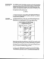
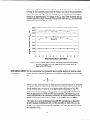
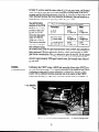
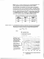
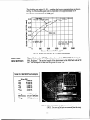
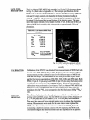
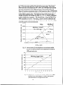
LA-13574-M
(ISPO-375)
Manual
The Underwater Coincidence Counter for
Plutonium Measurements in Mixed-Oxide
Fuel Assemblies Manual
UNITED STATES PROGRAM
FOR TECHNICAL ASSISTANCE
TO IAEA SAFEGUARDS
Los Alamos
'NATIONAL
LABORATORY
Los Alamos National Luborato y is operated by the University of Gdifomia
for the United States Department of Energy under contract W-7405ENG36.
Edited by Amy F&on-Stout, Group CIC-1
This work was supported by the US. Department of Energy, Ofice of
Nonproliferafion and National Security, International Safeguards
Division, and Programfor Technical Assistanceto IAEA Safeguards.
An Ajirmative
Action/Equal
Opportunity
Employer
This report was prepared as an account of work sponsored by an agency of the United States
Government. Neither The Regentsof the Un~ersity ofCab$xnia, the ?Inited St&esGommtit
anyagency thweof,noranyoftheiremployees,makesanywarra~ty,expressorimplied,orassumesany
legal liability or responsibility fbr the accuracy, completeness,or usefulness of any in@vnation,
apparatus, product, or processdisclosed,or representsthat its usewould not infringe privately owned
rights. Referenceherein to any specijc commercial product, process, or service by trade name,
trademark, manufacturer, or otherwise, does not necessarily constitute or imply its endorsement,
recommendation, or favoring by The Regents of the Unimsity of Califimia, the United States
Government, or any agency thereof. The views and opinions ofauthors expressedherein do not
necessarily state or refzect those of The Regents of the University of Califimia, the United States
Cbvernment,oranyagency
thereof.
TheLosAlamosNational
Laboratory stronglysupportsacad~‘c
j?eedomanda researcher’sright to publish; there/ore,theLaboratoyasan institutiondoes notendorse
the viewpoint of a publication or guarantee its technical correctness.
LA-1357&M
Manual
(ISPO-375)
UC-706
Issued:May 1999
USER’S MANUAL
The Underwater Coincidence Counter for Plutonium
Measurements in Mixed-Oxide Fuel Assemblies
G.
H.
M.
M.
W. Eccleston
0. Menlove
Abhold
Baker
+InternationalAtomic Energy Agency, Wagramrstrasse, Vienna, A-1200, AUSTRlA
Los Alamos
NATIONAL
LABORATORY
Los Alamos, New Mexico 87545
TABLE OF CONTENTS
ABSTRACT ................................................................................................................................................
1
INTRODUCTION
......................................................................................................................................
2
UWCC DESIGN ........................................................................................................................................
3
PREAMPLIFIER
(PDT-21 OA) ..................................................................................................................
4
COINCIDENCE
ELECTRONICS
...........................................................................................................
5
PROGRAM .......................................................................................................
5
PLATEAU .....................................................................................................................
6
DEAD TIME ................................................................................................................................................
6
MULTIPLICITY
7
INCC MEASUREMENT
HIGH-VOLTAGE
DEAD TIME .....................................................................................................................
NEUTRON DIEAWAY TIME ............................. . ....................................................................................... 7
EFFICIENCY ..............................................................................................................................................
MULTIPLICATION
CONSTANT ............................................................................................................
CROSS-CALIBRATION
9
IO
.........................................................................................................................
11
BORON EFFECTS .................................................................................................................................
12
BORON EFFECTS ON UWCC MEASUREMENTS..
BORON CONCENTRATION
MEASUREMENT
........................................................................ .I3
................................................................................. 13
MOL FUEL DESCRIPTION
...................................................................................................................
14
LANL FUEL DESCRIPTION
.................................................................................................................
15
CALIBRATION .........................................................................................................................................
15
MOX PIN REMOVAL ...............................................................................................................................
15
UWCC AIR MEASUREMENTS
............................................................................................................
.I8
RESULTS .....................................................................................................................
18
SUMMARY ................................................................................................................................................
19
ACKNOWLEDGMENTS
........................................................................................................................
.I9
.......................................................................................................................................
19
CALIBRATION
REFERENCES
APPENDICES
A
PWR Fuel Array Mockup ................................................................................................................
A-l
B. UWCC Measurements
of Fresh PWR MOX Fuel in Unborated Water.. ............................... B-l
C. UWCC Measurements
of Fresh PWR MOX Fuel in Borated Water.. .................................... C-l
D. UWCC Measurements
of Fresh PWR MOX Fuel in Air.. ......................................................... D-l
E. UWCC
Cross-Calibration
F. UWCC User Procedures..
Data.. .................................................................................................
E-l
............................................................................................................
F-l
G. INCC Setup and Operational
Steps for UWCC Measurements
........................................... G-l
.
LIST OF FIGURES
Figure 1.
UWCC positioned around the Los Alamos PWR MOX fuel assembly to provide
plutonium verification measurements
underwater . . . . . . . . . . . . . . . . . . . . . . . . . . . . . . . . . . . . . . . . . . ..~.........2
Figure 2.
Underwater
Figure 3.
UWCC forks showing polyethylene
Figure 4.
Wiring from 3He tubes to the PDT-21 OA Amplifier . . . . . . . . . . . . . . . . . . . . .. . . . . . . . . . . . . . . . . . . . . . . . . .. . . .. . . . . 4
Figure 5.
PSR-B multiplicity
Figure 6.
Calibration curve for PWR MOX fuel verifications in borated water using INCCcorrected doubles measurement data . . . . . . . . . . . . . . . . . . . . . .. . . . . . . . . . . . . . . . . . . . . . . . . . . . . . . . . . . . . . . . . . . . . . . . . . . . . 5
Figure 7.
UWCC detector high-voltage
Figure 8.
Doubles rate versus the coincidence gate width for the UWCC in air with a 252Cf
source and in water from a PWR MOX fuel assembly. . . . . . . . . . . . . . . . . . . . . . . . . . . . . . . . . . . . . . . . . . . . . . . . . 8
Figure 9.
Relative statistical error for the doubles rate versus gate setting for 252Cf in air
and for a PWR MOX fuel assembly in water . . . . . . . . . . . . . . . . . . . . . . . . . . . . . . . . . . . . . . . . . . . . . . . . . . . . . . . . . . . . . . . . . . 9
Coincidence
Counter (UWCC) . . . . . . . . . . . . . . . . . . . . . . . . . . . . . . . . . . . . . . . . . . . . . . . . . . . . . . . . . . . . . . . . . . . 3
and the cabling to the 3He neutron detectors.4
shift register connected
to the UWCC signal summer box.......5
bias plateau curve . . . . . . . . . . . . . . . . . . . . . . . . . . . . . . . . . . . . . . . . . . . . . . . . . . . . . . .. . . 6
Figure IO. UWCC neutron singles, doubles, and multiplication-corrected
doubles response
vs position (cm) of the PWR MOX fuel assembly along the length of the UWCC
arms . . .. . . . . . . . . . . . . . . . . . . . . . . . . . . . . . . . . . . . ..*....................................................*.......*............................. IO
Figure 11. UWCC cross-calibration
geometry
and 252Cf source-holding
fixture . . . . . . . . . . . . . . . . . . . . . . 1 1
Figure 12. The UWCC gate fraction vs dieaway time for gates of 64 and 128 us . . . . . . . . . . . . . . . . . . . 12
Figure 13. MCNP simulation of UWCC measurements on a 17 x 17 MOX PWR fuel
assembly with and without a cadmium cover. . . . . . . . . . . . . . . . . . . . . . . . . . . . . . . . . . . . . . . . . . . . . . . . . . . . . . . . . . . . . 13
Figure 14. Doubles gate ratio (DGdjD128) vs boron concentration . . . . . . . . . . . . . . .._................................ 14
Figure 15. Mol PWR MOX fuel array positioned underwater in the UWCC. Two rows of fuel
pins are removed from the array . . . . . . . . . . . . . . . . . . . . . . . . . . . . . . . . . . . . . . . . . . . . . . . . . . . . . . . . . . . . . . . . . . . . . . . . . . . . ~. . . . . . . 14
Figure 16. UWCC calibration geometry with the Los Alamos 1 &pin x 15-pin MOX fuel
assembly . . . . . . . . . . . . . . . . . . . . . . . . . . . . . . . . . . . . . . . . . . . . . . . . . . . . . . . . . . . . . . . . . . . . . . . . . . . . . . . . . . . . . . . . . . . . . . . . . . . . . . . . . . . . . . . . . . . . . . . . .... 15
Figure 17. Multiplication-corrected
neutron doubles (Dmc) for PWR MOX fuel arrays in Mol,
Belgium, and Los Alamos in unborated water . . . . . . . . . . . . . . . . . . . . . . . . .. .. . . . . . . . . . . . . . . . . . . . . . . . . . . . . . . . . 16
Figure 18. Neutron triples and doubles/l 0 versus 240Puefffor PWR MOX fuel in 2200-ppm
borated water . . . . . . . . . . . . . . . . . . . . . . . . . . . .. . . . . . . . . . . . . . . . . . . . . . . . . . . . . . . . . . . . . . . . . . . . . . . . . . . . . . . . . . . . . . . . . . . . . . . . . . . . . . . ..*....... 16
Figure 19. Neutron doubles (D) and multiplication corrected neutron doubles (Dmc) for PWR
MOX fuel arrays in Mol, Belgium, and Los Alamos in 2200-ppm borated water. .I 7
Figure 20. Multiplication corrected neutron doubles calibration for a PWR MOX fuel array in
Mol, Belgium, Los Alamos, and inspection field measurements
in 2200-ppm
borated water . . . . . . . . . . . . . . . . . i . . . . . . . . . . . . . . . . . . . . . . . . . . . . . . . . . . . . . . . . . . . . . . . . . . . . . . . . . . . . . . . . . . . . . . . . . . . . . . . . . . . . . . . . . . . . . . . . . . . 17
Figure 21.
Neutron doubles and multiplication corrected doubles calibration for PWR MOX
fuel in air . . . . . . . . . . . . . . . . . . . . . . . . . . . .. . . . . . . . . . . . . . . . . . . . . . . . . . . .. . . . . . . . . . . . . . . . . . . . . . . . . . . . . . . . . . . . . . . . . . . . . . . . . . . . . . . . . . . . . . . . ..... 18
LIST OF TABLES
Table I.
UWCC Helium-3
Detector
Specifications
Table II.
UWCC Measurement
Table Ill.
Californium
Table IV.
UWCC Dieaway Time Measurements
Table V.
UWCC Multiplication
Table VI.
252Cf (Cf-8) Reference
Table VII.
Mol MOX Fuel lsotopics.. .................................................................................................
Parameters
..................................................................... .4
Setup.. .................................................................... .6
(Cf7) UWCC Dieaway Time Measurements
in Air ................................. 7
for a PWR MOX Assembly
in Water ......... ...8
Constants.. .................................................................................. .I 1
Rates for Cross-Calibration
.................................................. .I2
.I4
Table VI II. Los Alamos MOX Fuel lsotopics.. ................................................................................. .I5
USER’S MANUAL
THE UNDERWATER COINCIDENCE COUNTER
FOR PLUTONIUM MEASUREMENTS IN MIXED-OXIDE
ASSEMBLIES
FUEL
G. W. Eccleston,H. 0. Menlove, M. Abhold, M. Baker, and J. Pecos
ABSTRACT
This manual describesthe Underwater Coincidence Counter (UWCC)
that has been designedfor the measurementof plutonium in mixedoxide (MOX) fuel assembliesprior to irradiation. The UWCC uses
high-efficiency 3Heneutron detectorsto measurethe spontaneousfission and induced-fission rates in the fuel assembly. Measurements
can be made on MOX fuel assembliesin air or underwater. The
neutron counting rate is analyzedfor singles, doubles, and triples time
correlations to determine the 240Pueffective massper unit length of the
fuel assembly. The system can verify the plutonium loading per unit
length to a precision of less than 1% in a measurementtime of 2 to 3
minutes. System design, components,performance tests, and operational characteristicsare describedin this manual.
(L-R) I? DeBaere @k-atom), G. Eccleston (LANL), I. Cherradi (IAEA), and
H. Menlove (LANL), with the UWCC.
1
INTRODUCTION
The use of fresh uranium-plutonium mixed-oxide(MOX) fuel in light-water
reactors is increasing in Europe and Japan,and it is important for inspectorsto
verify the plutonium content in the fuel for international safeguardspurposes.
Therefore, an improved underwater coincidence counter (UWCC), shown in
Fig. 1, has been developedto verify fresh MOX fuel subassembliesin air or
underwater at reactor storageponds. The UWCC can be configured to measure either boiling-water reactor (BWR) or pressurized-waterreactor (PWR)
fuel assemblies.
Fig. I. UWCCpositioned around the Los Alamos PWR MOX fuel
assembly to provide plutonium ven!cation measurements underwater
The UWCC useshigh-efficiency 3He neutron detectorsto measurethe spontaneous-fission and induced-fission rates in the fuel assembly.The neutron
counting rate is analyzedfor singles (S), doubles (D), and triples (T) time
correlations to determine the 240Pueffective mass,as well as the reactivity of
the fuel assembly.The UWCC can verify the plutonium loading per unit
length to a precision of under 1% in a measurementtime of 2 to 3 minutes.
Calibration of the UWCC was determined through measurementsof MOX
fuel in Mol, Belgium, and in Los Alamos. The Mol fuel array allowed calibration measurementsup to 240Pueffective loadings of 6.8 g/cm. The Los
Alamos MOX fuel allowed the calibration to be extended up to a 240Pueffective loading of 14.83 g/cm.
This manual provides the design specifications, performance tests, operational
parameters,and preliminary calibration information for the UWCC.
2
UWCC DESIGN
The UWCC design was basedon MCNP calculations. These calculations
attempted to determine the effects of cadmium and to specify the front and
back dimensions of polyethylene located around the detectors,which optimize
efficiency while reducing the effect of boron concentration.The goals of the
UWCC developmentwere:
l
l
l
l
l
l
l
underwater partial defect verifications (~6% 1 sigma) on fresh MOX
fuel assemblies,
stainless-steelcladding for improved decontamination,
measurementtime less than 5 minutes per assembly,
configurable for measurementsof BWR and PWR MOX fuel subassemblies,
insensitivity to detector positioning around a fuel assembly,
use of standardneutron coincidence shift-register electronics and assay
software, and
compatible size and weight for transportation, field setup, and use.
The selecteddesign for the UWCC (shown in Fig. 2) consists of eight 7.5
atmosphere3He neutron detectorsembeddedin polyethylene, with 2.5 cm of
polyethylene in front and 3.8 cm behind the detectors.Four detectorsare
located in each of
the UWCC forks.
The polyethylene
is wrapped in
cadmium and
located in a
watertight stainless-steelenclosure. A stainlesssteel bellows
allows signal
cables to be
connectedbeFig. 2. Underwater Coincidence Counter (UWCC).
tween the detectors and the
UWCC pipe and preamplifier. A stainless-steelbackplate contains a pipe
holding the PDT-210A dual AMPTEK preamplifier.’ Stainlesssteel is used on
all external componentsfor decontamination.
In addition to providing improved decontamination,the stainlessshell also
protects the cadmium liner, which is positioned around the high-density
polyethylene on the inside of the shell. The stainlessshell is watertight and
sealedwith standardstainless-steelscrews and 0 rings, permitting measurements to be performed underwater.
3
PREAMPLIFIER
(PDT-210A)
To decreasethe UWCC sensitivity to varying boron concentrations in the water, we placed
a 0.5-mm liner of cadmium
inside the stainless-steelforks
which completely surrounds
the polyethylene containing the
detectors.For gamma-ray
shielding and neutron absorption, the cadmium liner thicknesswas increasedto 1.0 mm
in the location directly between Fig. 3. UWCC forks showingpolyethylene and the
cabling to the 3He neutron detectors.
the fuel assemblyand the 3He
tubes. The
cadmiumTable I. UWCC Helium- 3 Detector Specifications
covered
Detector Parameters
Value
polyethylModel number
RSP4-081
l-105
Number of tubes
8
ene conGas pressure
7.5 atmospheres
tains the
Tube cladding
aluminum
Active length
3He detec277 mm
tors, as
shown in
Fig. 3. Each of the UWCC forks contain four 3He tubes with the specifications listed in Table I.
The UWCC usesa dual-channelPDT-210A amplifier with one AMPT.EK
channel for four 3He detectors.Figure 4 shows the wiring between the 3He
tubes and the PDT-210A amplifier. The detectors are cross-wired between the
two forks and each AMPTEK channel collects signals from two detectorsin
each fork. The cable length between the 3He tubes and the PDT-210A amplifier is approximately 45 mm.
The amplifier output pulse is
set for 50 ns. The distance
between the PDT210A and
the shift register should be
20 m or less.
Fig. 4. W7ringfrom
3He tubes to
the PDT-21 OA
PDT 2i O-A
Dual Ampteks
A signal summer box, shown
in Fig. 5, connectsthe PDT210A to the shift-register
electronics. The summer box
passesHV and +5V from the
shift-register module to the
PDT-210A and ORs the
output of the two digital
pulses to produce one pulse
stream, which is then fed into
the shift register.
COINCIDENCE
ELECTRONICS
Commercial shift-register products meeting the requirementsfor UWCC
neutron multiplicity/coincidence measurementswith the INCC program are
the Advanced Multiplicity Shift
Register from Ortec, and the
PSR and PSR-B modules from
Aquila Technologies.The PSRB module is shown in Fig. 5.
The UWCC functions with
older coincidence shift-register
electronics such as the JSR-11
and JSR-12. Measurementsof
the neutron singles (S) and
doubles (D) are provided by
these units2 A two-parameter
analysis provides fuel-assembly Fig. 5. PSR-B multiplicity sh@ register
connected to the UWCCsignal summer box.
verification but lacks triples
flags. Triples measurementsare obtained from multiplicity measurements.
These also provide information indicating whether measurementconditions are
appropriate to declaredconditions.
The UWCC is operatedusing the Integrated Neutron Coincidence Counting
INCC
MEASUREMENT (INCC) software program. The program communicateswith a shift register
PROGRAM
through the serial port of a PC computer. The INCC program controls the shift
register, setsUWCC operational parameters,and receivesneutron singles,
doubles, and multiplicity signals. These signals are collected by the shift register.
The INCC program analyzesthe UWCC measurementdata and displays the
results within a few secondsfrom the time each measurementis completed.
Count rates are corrected for detector dead time. The neutron doubles, D, are
corrected for multiplication using the known-alpha method.3The UWCC measurementsprovide underwater verification of the 240Pueffective rate of fresh
MOX fuel based on a calibration curve, shown in Fig. 6.
Multiplication
Corrected
240Pueff
Doubles
(g/cm)
Fig. 6. Calibration curve for PWR MOXfuel verijkations
in borated
water using ZNCC-corrected
doublesmeasurement
data,
5
HIGH-VOLTAGE
PLATEAU
Before measuringthe high-voltage plateau for the UWCC, the two
PDT-21OAchannelswere matched to have the same gain. Figure 7 shows the
plateau curves for channelsA and B for the 3He tubes (RS-P4-0811-105).The
PDT-210A preamplifier allows the UWCC high-voltage operating bias to be
the standard
?3wo
1680 volts
7cm
used for
FL
safeguards
ye Booo
neutroncl 5030
measurement
2
rsystems.
iij
5 3wil
5
3 2ooo
loo0
1700
Detector High Voltage
Fig. 7. WCC
DEAD TIME
Bi~~volts)
detector high-voltage biasplateau curve.
The counting rates for the UWCC are high (approximately 100 kHz) for MOX
fuel assemblies,which causesa significant electronic deadtime effect. The
dead time was measuredusing two 252Cfsourcesthat had a known absolute
ratio of neutron emission rates.The ratio for sourcesCf-10 to Cf-4 is 55.6.
The deadtime equationsfor corrected rates for the singles and doubles are
given by
5s
S(c0r-z) = S(meas)e T
D(corz) = D(mear)p
where
6=(a+b*S*104)
PS
and the deadtime parametersa/b = 1. The measurementparametersrequired
for the INCC program under the setup” heading are listed in Table II.
Table II. UWCC Measurement
Parameter
UWCCI
Gate Length
High Voltage
Dieaway Time (air)
Efficiency
Parameters
uwcc2
Setup
uwccs
psec
HV
7, ps
E
64
1680
38
0.05
64
1680
38
0.05
64
1680
38
0.05
Dead Time
Coefficient
Coefficient
Coefficient
d
A
B
C
500
2.15
2.15
35
500
2.18
2.18
30.5
500
1.9
1.9
0
Doubles-Gate Fraction
Triples-Gate Fraction
fg
tg
0.70
0.49
0.70
0.49
0.70
0.49
Multiplicity
Deadtime
Deadtime
Deadtime
6
MULTIPLICITY
DEAD TIME
For multiplicity analysis, the deadtime corrections are done with the equations
derived by Dytlewski4 using a constant deadtime value d. The value of d was
determined by measuring several 252Cfsourceswith different neutron source
strengths.The triples/doubles multiplicity ratio should be independent of the
neutron source strength after deadtime correction. The value of d that gave the
best agreementwas the maximum value:
dGOOns.
A multiplicity dead time of 500 ns requires a shift-register gate setting of 64
ps or larger. The additional multiplicity deadtime coefficient C was required
for units UWCC 1 and UWCC2.
NEUTRON
DIEAWAY TIME
The neutron dieaway time z of the UWCC was measuredusing source Cf-7.
Table III lists the gate widths and the doubles rates and errors. The resulting
dieaway time in air is approximately 37 ps for a gate setting of 64 vs.
Table Ill. Californium
(Cf7) UWCC Dieaway
Time Measurements
in Air
Gate Length
(I.Ls)
Parameter
UWCCI
32
Singles, cps
Doubles, cps
D,,, 0%
2, p
17898
2260
0.32
64
Singles, cps
Doubles, cps
D,,, 0%
7, ps
17899
3200
0.281
36.5
128
Singles, cps
Doubles, cps
Derr, 0%
x, ps
17902
3803
0.36
38.6
Boron in the pool affects the multiplication of the MOX fuel assembly,which
in turn affects the dieaway time of the system. Measurementsat two dieaway
time gate settings can confirm the boron content in a pool. Figure 8 shows
the doubles rate versus the gate width for a *Yf source in air (bottom curve)
and a PWR assemblyin unborated water (top curve).
In addition to the measurementsfor a 252Cfsource in air, the dieaway time
was measuredfor a PWR MOX fuel assembly in pure water at Los Alamos.
This information is provided in Table IV. The dieaway time increasesfrom
7
approximately 38 ps for *Yf in air to approximately 78 p for a MOX assembly in pure water. The reasonfor the increaseis the long neutron-multiplica-
I
Table IV. UWCC Dieaway Time Measurements
for a PWR MOX Assembly in Water
I
Gate Length
Q-==)
32
128
I
I uwccrl
Parameter
I
Singles, cps
Doubles, cps
D,,, 0%
2, ps
100490
5995
1.264
Singles, cps
Doubles, cps
D,,, 0%
2, p
100540
10137
1.144
-86
Singles, cps
Doubles, cps
Derr, 0%
7, us
14258
3803
1.259
-71
tion fission chains that occur when a MOX fuel assemblyis placed underwater. The induced fissions from multiplication add several neutron-thermalization time intervals to the dieaway time.
Figure 8 shows a graph of the normalized doubles rate as a function of gate
width for a *‘*Cf source in air and a MOX assemblyin pure water with the data
normalized to unity for at the 32q.s gate width.
U WCC Measurement
Jan 20,1098
Fig. 8. Doubles rate
versus the
coincidence gate
width for the
UWCC in air
with a 252Cf
source and in
waterfrom a
P WR MOX fuel
assembly.
Gate Wkith [usec)
8
Figure 9 shows the relative counting statistical error versus the gate length for
the same cases(air and water). The error is a minimum for a gate setting at
approximately 80 j.tsin water.
For the case of MOX fuel in borated water, the dieaway time is slightly higher
than for air (approximately 40 p). Since most MOX fuel assembliesare
stored in borated water, we have chosena gate setting of 64 ps for applications
of the UWCC to MOX fuel assemblies.A gate increaseto 128 ps would result
in a doubling of the counting time neededto obtain the same counting statistics obtained statisticsobtained for the 64-ps gate.
UWCC Relative Error versus Gate Width
January 20,1998
Fig. 9. Relative statistical errorfor the
doubles rate
versus gate setting
f or “Cf in air and
for a P WR MOX
fuel assembly in
water:
60
EFFICIENCY
loo
80
Gate Width (usec)
The efficiency of the UWCC was measuredby placing a calibrated 252cf
source in the center of the active zone. The measuredefficiency in air was
3.6% (PWR mode) for a 252Cfpoint source centered in the UWCC. For the
BWR geometry, the efficiency for a *“Cf source in air increasesbecausethe
two forks are moved closer together compared to the PWR configuration,
resulting in an efficiency of 5.1%. Becauseof the extended geometry and the
neutron absorption in the water, the averageefficiency for spontaneousfission
neutrons emitted over the geometry of a fuel assemblywill be considerably
less than this value.
The 3He tubes in the TJWCChave active lengths of 280 mm compared with
152 mm for the modified fork. The extra length was designedto provide more
efficiency and to make the counting rate less sensitive to the movement of the
fuel assemblyrelative to the fork during the measurement. The primary
drawback to these larger fork arms is the increasedweight for the UWCC.
The nylon bumper on the back of the UWCC is used to position fuel assemblies in the center of the maximum counting profile. The bumper has two
positions, which are determined by a set screw. The bumper is extendedfor
BWR assembliesand retracted for PWR assemblies.
9
Tests were performed to determine the change in counting rate as a function of
moving the fuel assemblyaway from the bumper and out of the measurement
area of the forks (seeFig. 10.) A 2-cm gap between the fuel and the bumper
results in an approximately 1% change in the Dmcrate. Both the totals and the
doubles rates have larger variations with position than the Dmc.The plutonium
calibration is basedon the Dmcrate.
900
800-
W---
Singled50
A-----
*.
Doubles/lo'
700
0
2
600-
2
OS
500 -
d
II
z
400 -
cl
3.
.-?
co
-&-
A
300
200 -1
.“-Q?dt
loo00
-5
-4
-3
-2
-1
0
1
MOX Fuel Position
2
3
4.5
6
7
in the UWCC
Fig. IO. UWCC neutron singles, doubles, and multiplication-corrected doubles
response vsposition (cm) of the PWR MOX fuel assembly along the
length of the UWCC arms.
MULTIPLICATION’
CONSTANT
For the conventional two-parameter known-alpha analysis of neutron coincidence data, the constantp0 representsa nonmultiplying sample and is defined
as:
PO=$(l+a)
where a is the calculated ratio of alpha-particle-inducedneutrons to spontaneous-fission neutrons. BecauseR is directly proportional to the gate fractionfg
for the doubles rate, we have p. at an approximate efficiency of * f,. We
cannot measurep. becausewe do not have a nonmultiplying fuel assembly
with the geometry of a PWR or BWR fuel assembly.The value of p. is directly proportional to the efficiency; therefore, the higher efficiency of the
BWR configuration will result in a higher p. for BWRs than for PWRs.
The value of p. can be determined using MCNP calculations to obtain the
neutron leakage multiplication (ML) of the assemblyin water. The p. is selected to give agreementbetween the MCNP value of M,and the two-p,arameter analysis of M,
10
In Table V, we have used the same value of pO for air, pure water, and borated
water for a given fuel type to provide consistencyduring setup of the INCC
program and for field measurements.Actually, pO increasesas the boron in the
water increasesbecausethe boron shortensthe dieaway time and results in a
larger fraction of neutrons appearingwithin the gate width.
The MCNP-REN
Table V. UWCC Multiplication
Constants
analysis of the PWR
Parameter
1 PWR
I BWR
MOX fuel assembly
I
provides values for
p. in air
0.026
0.019
f, in air
0.75@64/~
0.75@64 ps
pO that vary from
0.014 for unborated
p,in pure water
0.026
0.019
water to 0.020 for
fg in pure water
0.53@64ps
0.53@64 j.ts
2200 ppm of boron.
The boron concentrap,in 2200 ppm B
0.026
0.019
fg
in 2200 ppm B
0.73@64ps
0.73@64 p.6
tion can be checked
and estimated using
the doubles ratio from two gate measurementswhen a MOX fuel assemblyis
being measured.We have selecteda single pO value corresponding to 2200ppm boron concentration.The pO is selectedto give the true M, for the assembly in borated water. Since the majority of fresh MOX fuel assembliesare
stored in approximately 2200-ppm borated water, the borated water value of
pO was used.
CROSSCALIBRATION
Calibrating the UWCC using a MOX fuel assemblyallows other UWCCs to
be cross-calibratedusing a 252Cfsource positioned in the center of the UWCC.
A reference count rate for cross-calibrationis obtained by placing a %f
source with a calibrated neutron-emissionrate at the center of the UWCC
active zone (see Fig. 11.) The rates are listed in Table VI for both PWR and
252Cfsource
Fig. II.
UWCC cross-calibration geometry and "Cf
11
source-holding fucture.
BWR geometries. The data in Table VI are also corrected for dead time. The
UWCC parametersused for the measurementsare listed in Table IV.
When performing a cross-calibration,care must be taken to avoid neutron
reflection from the table or floor supporting the UWCC. The UWCC should
be positioned about one meter above the floor and at least a meter away from
the walls. A metal pushcart was used to support the UWCC when collecting
the cross-calibration data shown in Table VI. A special fixture, shown in Fig.
11, is supplied with the UWCC to hold the 252Cfsource in the center of the
active zone. The fixture adjusts to both BWR and PWR geometries.
Table VI.
*%f
(Cf-8) Reference
uwcc
I
Singles
=P=
Configuration
Rates for Cross-Calibration
Doubles
cps
(S)
I~
(D)
178.3 + 0.05
PWR
5800
I
I
350.6 f: 2.9
I
BORON EFFECTS
The multiplication constantp. is dependenton the boron in the water because
the boron decreasesthe die-away time (2) for neutrons in the fuel assembly.
This decreasein ‘I:results in an increasein the gate fraction& given by:
j-g = e-PD’Z(l_ e-Gfc)
where
PD = pre-delay (3 ps),
G = gate length (64 ps), and
z = die-away time.
Figure 12 shows a plot of fg versus z for the UWCC for gate lengths of 32,64,
and 128 ps. The 2
1.0
values for pure water
and berated water
were measuredfor a
0.8
PWR MOX assembly
hr,
and the values are
indicated in Fig. 12. g 0.8
The resulting changes i
in the fg values
0.4
change the effective
p. by approximately
37%.
0.2
0
20
40
Die-Away
60
80
Time tuscc)
100
120
Fig. 12. The VWCC gate fraction vs dieaway time for gates
of 64 and I28 ,us.
12
BORON EFFECTS
ON UWCC
MEASUREMENTS
Spent-fuel storage ponds have boron contents that range from zero to several
thousand ppm, with most ponds containing approximately 2200 ppm. Increasing the boron concentration in a spent-fuel pond increasesthe neutron absorption rate, reducing the number of neutrons emitted from a MOX fuel assembly that reach the UWCC and resulting in a lower counting rate. This rate
change causesa calibration change that is a function of the boron concentration. Surrounding the UWCC with a cadmium layer removes thermal neutrons that are similar to boron as they enter the UWCC, reducing the effect of
varying boron concentrations.Figure 13 shows the UWCC neutron singles
rate as a function of boron concentration from a 17-pin X 17-pin MOX PWR
fuel assembly.The MCNP results are plotted for the UWCC with and without
cadmium. Cadmium covering the UWCC flattens the efficiency response
compared to no cadmium, and it reducesthe efficiency changesdue to changing boron concenI
I
tration. The
UWCC-measured
Dmcin Fig. 13 is
relatively flat
(between lOOOand 2250-ppm
boron), indicating
that two Dmc
calibration curves
are sufficient for
the UWCC to
t
/’
M&wad
Multiplication
Cor,rected Doubles (Cd)
cover unborated
I
i
07
and borated
0
500
loo0
1500
2ooo
ponds.
Boron Concentration @pm)
,oOOO
&--J--.-t
._.....
I
Figure 13 is a plot
Figure 13. MCNP simulation of UWCC measurements on a I7 X
of the correlation
MOXPWR fuel assembly with and without a cadmium
between the boron
cover.
concentration and the doubles coincidence ratio (64~ps/128-l.t.sgates) measured by the UWCC on a 17 X 17 PWR MOX fuel assembly.
BORON
CONCENTRATION
MEASUREMENT
I7
For MOX fuel assembliesstored underwater, the boron content can be confirmed from a dieaway time z ratio measurementwhen a fuel assemblyis
located in the UWCC. The boron concentration in parts per million is determined with the UWCC by measuring a fuel assembly at two shift-register gate
settings. This is possible since the boron concentration affects the die-away
time and not the efficiency of the UWCC. The shift-register gate settings are
changed in the INCC program in the “Measurement Parameters,”located
under the “settings” file menu. The normal doubles-rate measurement,D64,
takes place with a 64-ps gate setting. If a second doubles-ratemeasurement,
Drz8,of approximately 5 minutes is made with a second shift-register gate
setting of 128 l.ts,then the boron concentration can be determined.
13
The doubles gate ratios, DJD,,,, confirm the boron concentrationsas shown
in Fig. 14. The doubles gate ratio is expectedto be approximately 0.79
for a boron concentrationof 2200 ppm.
3
0.77
z
c
0.75
zf
;
.c
=
a
0.73
0.71
$j 0.69
Q) s
li:
3 0.67
PO
0.65
0
500
1000
1500
Boron Concentration,
2000
2500
ppm
Fig. 14. Doubles gate ratio @64/D,2J vs boron concentration.
Figure 15 shows the UWCC positioned around the PWR MOX fuel array in
Mol, Belgium. 5 The active length of the plutonium in the Mol fuel rods is 50
cm. The isotopics for the fuel are given in Table VII.
MOL FUEL
DESCRIPTION
rable VII. Mel MOX Fuel lsotopics
16-Jan-1998
U8Pu
U9Pu
2’OPu
2’1Pu
UZPu
2”Alll
2~PUen
MOX Array
mpuen
0.054
81.218
17.582
0.689
0.456
2.432
%
%
%
%
%
%
0.02575 g/c&pin
15 x 15 = 204 pins
6.798 g/cm/array
Fig. 15. A401PM? MOXfuel array positioned underwater in the
UWCC. 23~0rows offuelpins are removedfiom the array.
14
LANL FUEL
DESCRIPTION
The Los Alamos PWR MOX fuel assemblyis a 15-pin X 15-pin array, shown ’
in Fig. 16. (Refer also to Appendix A.) The isotopic specifications for the
MOX rods are listed in Table VIII below. For the full 204-rod array (204 fuel
rods and 21 empty control-rod channels) the linear plutonium loading is
14.83 g 240Pu,Jcm.The UWCC is 17.3 cm tall and it is sensitive to the fuel
for about 10 cm beyond the top and bottom of the detector arms. The measured fuel region extends over a height of about 37 cm. In the case of the Los
Alamos MOX fuel assembly,this correspondsto approximately 2.5 kg of
plutonium.
Table VIII. Los Alamos
lsotopics
MOX Fuel
IS-Jan-1998
u8Pu
2J9Pu
2’OPu
2’fPu
2’2Pu
UIAm
240pueN
MOX Array
2&Puen
0.673
77.580
17.799
2.367
1.581
4.734
%
%
%
%
%
%
0.0727 g/cm/pin
15 X 15 = 204 pins
14.83 g/cm/array
Fig. 16. WCC calibration geometry with the
Los Alamos ISpin X IS-pin MOXfuel
assembly.
CALIBRATION
MOX PIN
REMOVAL
Calibration of the UWCC was obtained from measurementsof MOX fuel rods
located at the SCK-CEN facility in Mol, Belgium and at Los Alamos. These
measurementsprovide calibration data for two different types of MOX fuel
rods and fuel arrays. The calibrations at Mol were performed in pure water
and for five boron concentrations (530,909,1540,2160, and 2250 ppm). Both
PWR (17-pin X 17-pin array) and BWR (g-pin X g-pin array) fuel arrays were
used for the measurementsat the VENUS facility. Borated and unborated
calibrations were performed at Los Alamos. The Los Alamos PWR MOX fuel
array is a 15 Xl5 configuration and the fuel contains more than twice the
plutonium (14.838 240Pue,/cm)
compared to the Mol fuel array (6.8Og240Pu,J
cm).
The effects of plutonium loss through pin-removal load were determined
starting with full MOX arrays. The full MOX fuel arrays in Mol, Belgium (17
X 17 = 264 pins) and in Los Alamos (15 X 15 r 204-p&) weremeasured=
Pins were then removed from selectedinterior rows to reduce the plutonium
content. Measurementswere made for the case where water replaced the
MOX rods. One set of measurementswere collected with UO, fuel rods
(containing a depleted-uraniumcontent of 0.2%) replacing the MOX rods.
The neutronsinglesandneutrondoublesratesaredependent
on thespecific
15
configurations. The multiplication correction removes this dependence.The
multiplication-corrected neutron doubles rate versus the 240Pu-effective
content is a straight line.
Figure 17 shows the the Dmcrateversus the 240Pu-effectivelinear loadings in
unborated water.
The samep. (0.19)
LANL MOX
was used for both
176 cm fuyl length
the fresh water and
the borated water
calibration measurements.This
value of p. is
required for verification measure50 cm fuel Imngth
ments when using
the calibration
curve in Fig. 17.
The limited length
240Pu,ff (gmlcm)
of the Mol MOX
fuel (50 cm) shows
Fig. 17. Multiplication-corrected neutron doubles (o,, for
an end effect that
PE?R MOXfuel arrays in Mol, Belgium and Los
has been corrected
Alamos in unborated water
using MNCP calculations that extend the fuel to a length of 130 cm. The end
effect is negligible for the borated water case.
Figure 18 comparesthe triples with doubles for the Los Alamos MOX fuel
array which was measuredin 1500-ppm boron and extrapolated to 2200-ppm
boron. The triples precision is 24% in 10 minutes. Counting periods of
about 10 minutes might be required to make quantitative use of the triples
count. The triples rate as a function of the 240Pu-effectivemassis shown in
Fig. 18. The ratio of T/D and T/S could be used to resolve anomalous results
or differences between the calibration condition artd the field condition. The
ratio of T/D
approximately
equal to e and T/
S approximately 3^ 500
8
equal to e2is a
?j 400
Doubled10
function of the
s
n
300
efficiency and
-0
s
the size and
3
200
configuration of z.
the fuel assem- z 100
bly that could be
0
16
12
14
6
10
4
6
0
2
evaluated using
240Pucff (g/cm)
these ratios.
Fig. 18.
16
Neutron triples and doubles/IO versus 240Pu, for
PWR MOXfiel in 2200~ppm borated water.
Plutonium-calibration measurementsare basedon the DmCresults shown in
Fig. 17 for pure water and Figs. 19 and 20 for borated water. The LANL
MOX fuel array was measuredin 500-, lOOO-,and 1500-ppm boron and the
data were extrapolated to the 2200-ppm boron values shown in Fig. 19.
Figure 20 contains measurementdata for field inspection trials of PWR MOX
fuels which have much larger loadings plutonium compared to the Mol and
LANL MOX calibration pins. The calibration data in Fig. 20 provide a
straight calibration line through the origin, DmC= 24.1 x, which is dependent
on the multiplication constantpr We estimated the p0 listed in Table V for
PWR assembliesto be 0.19. The samep. must be used for calibration and
subsequentassay,and its absolute value is important only where the multiplication M must be correctly determined.
0
2
4
6
6
240pbff
10
12
14
16
(g/cm)
Fig. 19. Neutron doubles (0) and multiplication corrected neutron doubles
(DJ for PWR MOXf ue1 arrays in Mel, Belgium and Los Alamos in
2200-ppm borated water
700
600Multiplication
Corrected
D,. = 24.1x
Doubles
600 -
0
2
4
6
6
10
12
240Pueff
14
16
16
20
22
24
26
(g/cm)
Fig. 20. Multiplication corrected neutron doubles calibration for a PWR
MOXfuel array in Mol, Be&urn, Los Alamos and inspection
field measurements
in 2200-ppmboratedwater
17
UWCC AIR
MEASUREMENTS
The UWCC can measureMOX fuel in air to verify the 240Pu,content in a
manner similar to the passive neutron coincidence collar6 We calibrated the
UWCC in air using the Mol and Los Alamos MOX fuel assemblies.The Mol
fuel pins are 50 cm in active length and show an end effect compared to the
177.8 cm active-length fuel rods at Los Alamos. The neutron doubles and Dmc
from air measurementsare shown in Fig. 21. The Dmcprecision is better than
1% in 10 min. The line has a negative intercept becauserod removal decreasesboth the plutonium source term and the efficiency from neutron backscattering from the ends of the fuel rods. The triples rate in air is low (8 f 7
cps) so the T measurementwould require very long counting times, so is
generally not useful.
8
8
Yiz
.
600.0
-
700.0
-
600.0
-
5oo.o
400.0
--
300.0
-
200.0
-
LAM. MOX Fual
Doubles
.
(D)
\
a
-E
3
E
05
uE
z
m
100.0
*’
Mel MOX Fuel
./*
.
_A’\
#(a,
-
a
z
0.0 7
n
0
\
Dmc
2
4
6
24OPu.ff
6
10
= -85.3 +39.0x
12
14
16
(g/cm)
Figure 21. Neutron doubles and multiplication corrected doubles
calibration for PWR MOXfuel in air
CALIBRATION
RESULTS
The UWCC measuresfull arrays of MOX rods and is able to verify if MOX
rods have been removed. Calibration results for full arrays of MOX rods in
2200 ppb boron go through origin and have a linear line of Dmc= 24.1 x.
In most of the calibration configurations where pins were removed, water
replaced the spacefrom a rod removal. However, for two of the configurations, low-enriched uranium rods (3.3% 235U)were substituted for the MOX
rods. The effects of these pin changesare detected by UWCC measurements.
The plutonium verification measurementsare normally based on the Dmc
calibration, and the counting precision for Dmcis better than 1% in 1 to 2
minutes. Two-parameter analysis using the known-alpha correction technique
removes multiplication effects from the doubles measurements. For cases
where LEU-fuel pins are substituted for MOX-fuel pins, the known-alpha
correction removes the multiplication effect created by the LEU pins and
permits verification of assemblieseven in the presenceof LEU-pin substitution. Additionally, the measurementuncertainties required for two-parameter
analysescan be obtained within about one order-of-magnitude reduction of
countingtime comparedto the timeneededto measurethe triples.
18
SUMMARY
The UWCC can be used to measurethe 240Pu,ff
per unit length in PWR
and BWR MOX fuel assembliesstored under water or in air. Verifications are based on calibration curves of Dmcversus 240Pu,g
per unit length.
This correction produces a straight-line calibration curve and has been
determined from measurementson two different MOX fuel arrays. The
statistical precision for Dmcis better than 1% for a two-minute count. The
UWCC can detect the removal of approximately 1% of the plutonium for
a relative measurementand 2-3% of the plutonium for an absolute measurement, depending on how closely the unknown matchesthe calibration
assembly.
The Dmccalibration makes the measurementsrelatively insensitive to
differences between the calibration condition and the field condition. The
calibration is insensitive to the number of fuel rods, diameter, pitch,
cladding, and LEU content. Separatecalibrations are required for pure
water and borated water. If separatep0values corresponding to pure and
borated water measurementsare used, then the calibrations will overlap.
To limit the potential for error in measurementsand reduce the chance of
an inconsistent p0 value, the same value (Table V) is recommendedfor all
measurements.
The appropriate calibration curve (borated versus unborated) is selected
based on the operator’s boron declaration. The boron loading can be
verified by calculating the doubles ratio (see Fig. 14) from a measurement
on a fuel assembly with two gate settings of 64 to 128 vs.
ACKNOWLEDGMENTS
The work reported in this manual was supported by the United StatesDepartment of Energy/International SafeguardsDivision (DOE/NN-44) and
the United StatesProgram of Technical Assistance(POTAS) to the International Atomic Energy Agency (IAEA).
REFERENCES
1. Precision Data Technology Corporation, Everett, Washington.
2. D. Reilly, et al., Passive Nondestructive Assay of Nuclear Materials,
ISBN o-16-0332724-5, March 1991.
3. N. Ensslin, “A Simple Self-Multiplication Correction for In-Plant
Use,” in Proc. 7th ESARDA Annual Symposium on Safeguards and
Nuclear Material Management, (Liege, Belgium, 1985), L. Stanchi,
Ed., Vol. 19, pp. 222-238.
4. N. Dytlewski, “Dead-time Corrections for Multiplicity Counters,”
Nucl. Instrum. Methods A305, pp. 492-494 (1991).
5. R. Charcon, et al., “Measurement of Fresh MOX-LWR Type Fuel
Assemblies Underwater,” SCK-CEN, Blg-766, Mol, Belgium, May
1998.
6. H. 0. Menlove, “Passive/Active Coincidence Collar for Total Plutonium Measurementof MOX Fuel Assemblies,”Los Alamos National
LaboratoryreportLA-9288-MX(ISPO-170)(May 1982).
19
APPENDICES
A. PWR Fuel Array Mockup
B. UWCC Measurementsof Fresh PWR MOX Fuel in Unborated Water
C. UWCC Measurementsof Fresh PWR MOX Fuel in Borated Water
D. UWCC Measurementsof Fresh PWR MOX Fuel in Air
E. UWCC Cross-Calibration Data
F. UWCC User Procedures
G. INCC Setup and Operational Stepsfor UWCC Measurements
20
Appendix A: PWR Fuel Array Mockup
Los Alamos 15 X 15 PWR Fuel Array
15
14
13
12
11
10
9
8
7
6
5
4
3
2
1
uwcc
Positioning
Bumper
ONMLK
JIHGFEDCBA
0
SUPPORT
Appendix A: PWR Fuel Array Mockup
Mol17 x 17 PWR Fuel Array
17
;B
15
14
13
12
11
10
9
8
7
6
5
4
3
2
1
-
QP
ONMLK
JIHGFEDCBA
l
SUPPORT
U-WC
Positioning
Bumper
Appendix R: UWCC Measurements of Fresh PWR MOX Fuel in Unborated Water
UWCC Meahrements of PWR
MOX fuel in unborated water
PWR Full Array 264MdX pins 50 cm Rod lend
?WR 17 MOX pins remokd born Row G
?WR 33 MOX pins remokd from Row G. Column 7
?WR 215 IMOX Pins 33 pins removed from Row G, Cot 7,l
J WR 17 UETJ(3.3%) tini &md in row G
Mel
264
36.77
6.80
64
960
40011
7.9
5869.8
20.9
1224.2
23.9
197.88
0.29
MO1
34.41
32.18
29.95
6.36
Mol
Mel
247
231
215
5.54
64
64
64
3800
600
600
38446
36470
34679
3.9
9.6
9.3
5647.3
5281.7
4988.8
10.1
23.9
22.6
1156.4
1081.1
979.6
11.3
26.1
24.1
lPO.04
181.31
172.88
0.14
0.34
0.32
Mel
247
34.41
6.36
64
609
37837
9.8
5522.5
24.9
1147.4
27.7
187.52
0.35
5.95
PWR
PWR
PWR
PWR
PWR
204 pin &II array
204 pin full array
15 MOX Dinsremoved from Row 7
29 MOX pins remohd From Row 7 , Cal G
41 MOX ahw removed fkom rows 7 & 10, Col G
LANL
Lhlc’L
LAhT.
Lm%
LAPI%
204
204
189
175
163
67.23
67.23
62.29
57.68
53.72
14.83
14.83
13.74
12.72
11.85
64
64
64
64
64
900
900
3360
Pal
Pal
125876
125791
119546
112868
105010
15.0
15.0
7.5
14.0
13.5
16369.5
16275.0
15641.3
14434.9
13330.3
71.7
71.5
35.0
63.0
58.0
2892.2
3063.4
2880.7
2734.7
2090.7
125.8
125.7
60.0
105.6
94.1
488.55
489.20
462.87
440.93
411.42
0.84
0.85
0.41
0.76
0.74
PWR
PWR
PWR
PWR
204 pin full array
15 MOX pins removed kom Row 7
29 MOX pins remov~h from Row 7, Co1G
41 MOX pins removed from rows 7 & 10. Co1 G
LAIVL
LAiK
LAW.
LAi%
204
189
175
163
67.23
62.29
57.68
53.72
14.83
13.74
12.72
11.85
64
64
64
64
900
3360
940
900
125791
119546
112868
105010
15.0
7.5
14.0
13.5
16275.0
15641.3
14434.9
13330.3
71.5
35.0
63.0
58.0
3063.4
2880.7
2734.7
2090.7
125.7
60.0
105.6
94.1
489.20
462.87
440.93
411.42
0.85
0.41
0.76
0.70
Appendix d. UWCC Measurements of Fresh PWR MOX Fuel in Borated Water.
.
12.5
332.
13.4
239.
4.6
181.
10.9
139.!
46.0
961.1
39.3
616.d
34.5
534.:
30.0
359.:
Appendix D: UWCC Measurements of Fresh PWR MOX Fuel in Air.
Ah Measurement
LANL & Mel Fuel Array
PWR MOX fuel
Tripln
Rat9
I
I
I
I
,a.-
. ..I
,
1
I
\“,-I
I
.80641
5.7)
343.51
9.11
8.:
i
t1L
YCIMp
MUltQ
COtWCt
Lkwbkm
COnSCtSd
Doubk Rata
Rata (c/s)
Error (e/s)
6.8
1.9
1.9
[
37.5
I
30.4
I
18.9
1
20.3
-_--- - _
NWX: Kod count on the measurements in rows 11 and 12 was off. There are 41 rods out with row 7,lO a1 co1G pulled.
* MOX rod in one position in col. G
Appendix E. UWCC Cross-calibration
Data.
Note: Cross-calibrations
in air should be performed with the UWCC unit sitting on a cart and away from surfaces
bias the cross-calibration
measurements caused by neutron reflections.
UWCC measurements
that would
in 1500 ppm boron on the LANL PWR 204 pln MOX Fuel Array
Doubles Fiatioa
lJwccxNwcc3
a The UWCC received an upgraded preamp (PDTZlO-A), compared to the original model, to mcrease gain and ahow the high voltage (HV) to be lowered from 1740 volts to the
standard 1680 volts used for coincidence counting measurements. UWCC-1 that was delivered to the IAEA corresponds to the cross-reference data for Cf-8 in air.
L%VCCl
UWCC neasurements
1680
3
64
in air on a wood benchtonb
0
0
N/A
0
uslna 252Cf source number
Cf-8
1000
5988
8
0.7
254.0
0.7
0.973
4.6
0.3
-
-
4.4
0.3
-
-
5.1
0.6
-
-
mcc!2
1680
3
64
0
0
N/A
0
Cf-8
1000
5816
1.0
247.4
0.7
0.9so
UWCC3
1680
3
64
0
0
N/A
0
CT-8
1000
6046
1.4
261.1
1.3
1.ooo
b
liuIcc1
~
Cross-calbrations are biased if performed on different benchtops, or benchtop positions, where the neutron retkction is changed
UWCC measurements
1680
3
64
In alr on a metal CartC using 252Cf source number 8
2.15
2.15
N/A
0
Cf-8
1000
5065
1.0
188.1
0.8
1000
4920
1.0
188.1
0.8
1000
5113
1.0
188.1
0.8
LWCKZ
1680
3
64
2.18
2.18
N/A
0
Cf-8
UWCC3
1680
3
64
2.18
2.18
N/A
0
Cf-8
3.8
0.3
-
-
0.949
3.7
0.3
-
*
,, 1.000
4.2
0.3
-
-
T 0.985.
,.
cCross-cahbrations were performed with the UWCC on a cart and away from adjacent wags to minimize neutron reflections.
,j
Appendix F
UWCC User Procedures
UWCC USER
PROCEDURES
There are two operational modes that use the UWCC:
A. Portable mode, in which the UWCC is shipped to the inspection site
and configured, inserted, then removed from the reactor pool after
each inspection visit; and
B. Fixed installation in the fuel-storage pool.
The user procedure describedbelow covers operational mode A. Operational mode B is a subsetof mode A.
The UWCC is operatedusing the IAEA neutron coincidence counting software (INCC) program. The electronics to support the UWCC are the same as
those used for the HLNC-2 and the AWCC (i.e., a JSR-12 and a PC). Any of
the shift-register or multiplicity electronics units may be used with the
UWCC. The particular unit used is specified in the INCC setup program.
Also, this program contains the setup information for the gate, predelay, IIV,
deadtime constants,etc. These can be entered into the INCC program or set on
the electronics unit, if manual setup is required, prior to the field exercise.
The first step in collecting UWCC verification measurementsis to configure
the mechanical pieces, connect the wiring to the shift-register electronics, and
then to the computer. Following system configuration, electronic tests are
performed and the UWCC can be placed into the pool. In the case of fixed
installations, the system would be maintained in the pool and all electronic
wiring would be in place. Once the UWCC is in the pool, electronics checks
and observationsare performed so that verification measurementscan car
rectly ensurethat the unit is operating properly and hasn’t been damaged.
The UWCC detector head and cablesare shipped in a reusable fiberglass case
with rolling wheels. The detector pipe sections that clamp together to reach
the appropriate depth in the water are shipped in tubes or boxes that are about
2-m long. The detector head contains the dual PDT-210A preamplifier and is
pre-assembledand sealedup to the point of the cable disconnect to the exten
sion pipes. The contents in the detector shipping container include:
l
l
l
the UWCC detector head (contigured to the PWR or BWR
measurementgeometry), ’
the protective fabric sleevesfor the arms ofthe fork,
the approximately 20-m of cable run to reach between the
head and the OR (sum) coupling box surface electronics,
F-l
l
l
the OR box to combinethe two signal lines from the PDT-21OA
amplifier to feed into the JSR-12,
the approximately40-cm cable extensionbetweenthe OR box and the
JSR-12,
l
a clamp to attachthe UWCC pipes to the side rail or bridge rail, and
l
all necessarytools for assembly.
The contentsin the electronic shipping containerinchtde:
UWCC ASSEMBLY
AND CHECKOUT
l
the JSR-12electronics,
l
shift-register connectioncablebetweenthe JSR-12 and computer,
l
computercontainingthe INCC software program, and
l
power supply and cablesfor the computer and printers if used.
1. Open the box containingthe detectorpipe sectionsand lay out the
necessarylengthsof pipe to reachthe fuel assemblies.
PROCEDURES
2. Open the fiberglasscasethat containsthe UWCC detectorhead box
and removethe UWCC measurementhead, OR (sum) coupling box,
signal cables,and fork protective fabric sleeves.
3. Carefully set the UWCC on a foam pad or piece of plastic. Note that
the welds on the thin stainlesssteel (SS) cladding of the UWCC could
crack if the UWCC is not handledcarefully. If thesewelds are damaged
and/or cracked,the UWCC could leak and the unit would be inoperable.
4. Check the UWCC configuration to ensurethat the fork positions and
the nylon bumper are set in the correct positions for the type of fresh
MOX fuel (PW R or BWR) to be verified.
5. Pull the 20m signal cablebundle through the SS pipe segmentsand
then clamp the pipe segmentstogetherto form a 6 to 7m long tube that has
the cablebundle threadedinside the tube.
6. Pull about lm of extra signal cable out of the pipe end and attach the
cable connectorsto the identified locations at the top of the UWCC (signalA,
signal B, +5V, and the HV). Attach the other end of the cable connectorsto
the identified locationson the OR coupling box.
F-2
7. Attach the two fork protective fabric sleevesto the arms of the
uwcc.
8. Make sure that the detector head is on a padded surface, to avoid
damaging the welds on the SS cladding. Carefully tip the UWCC on
its side so that the long SS pipe can be attachedto the top flange of the
detector head.
9. Have the facility operator attach lifting straps to the detector head and
the long pipe so that it can be lifted into the water. Have several inspectorsor facility staff help guide the system into the water. Keep the
open end of the SS pipe and cable bundle on the side of the pool.
10. Observe that there are no air bubbles coming from the detector head or
the pipe joints. Air bubbles would indicate a leak.
11. After the SS pipe is vertical, attach the clamps that will support the
UWCC to the side rail or to the bridge crane.
12. Extend the signal cable bundle to the location of the JSR-12 and
computer.Attach the cables to the OR box and the OR box to the JSR12 using the labels on the cables and OR box.
13. Turn on the JSR-12 in the manual mode and repeat step 6; however,
in this case the neutron signal will approachzero becauseof the water
shielding around the UWCC.
14. Attach the JSR-12 to the computer using the RS-232 cable.
INCC PROGRAM
SETUP
15. The UWCC is operatedwith the INCC program. The INCC program
should be configured prior to field measurements.If the INCC program
has not been configured and set up, refer to Appendix F for detailed proce
dures on setting INCC measurementparameters,etc.
16. Turn on the computer and the JSR-12 and review the INCC measurement
parameter settings under the Setup / MeasurementParametersoption.
Check that the correctshift-register type is selected (JSR-12 or other shift
register if used).
F-3
17. Using the Acquire / Rates Only option collect 3 measurementsof 10
secondseach to check the operation of the UWCC. Following the measure,
select the Reports / Rates Only option and review the output file to check
that the predelay, gate length, high voltage, dieaway time, and deadtimes are
all correctly set. Review the singles, doubles, and triples counts to check that
the UWCC is correctly counting.
18. Check and select the correct facility type, MBA, and detector ID (i.e.,
UWCCl) under the Setup/ Facility/ Inspection option.
19. Select or input the isotopics information under the Setup / Isotopics
option for the MOX-fuel assembliesto be verified.
20. Set the calibration analysismethod for the verification. Under the View
option select Maintain. Under the Maintain / Calibration option select
“Analysis methods”, then select the “Material type” and “Calibration
curve” for the passive-analysismethod.
2 1. Check the passive calibration curve parametersand curve t2ype by select
ing Maintain / Calibration / Passive Calibration Curve. The curve
.
type should be of the form “D = a+b*m+c*mA2+d*mA3.” The UWCC
calibration is a linear relationship with a zero intercept between the
multiplication corrected doubles @,,) and the 240Puc,
(g/cm) loading of a full
MOX fuel assembly.Therefore, the calibration constantsa = c = d = 0.0 and
only the constant b has a value which is dependenton the type of MOX fuel
assembly (PWR or BWR) and the boron content in the pool (0- or 2200 ppm).
The calibration constant for PWR MOX fuel, shown in Fig. 20, in a pond
containing 2200 ppm boron is b = 25.1 c/s/g/cm
BACKGROUND
MEASUREMENT
FRESH MOX
FUEL
VERIFICATION
22. Using the Acquire / Background option, collect 10 cycles of 30-set
background counts. The data source for this measurementshould be “Shift
register.” The UWCC should be under the water in the measurementconfigu
ration with no fuel assemblyinserted in the unit.
23. Have the operator center a fresh MOX me1 assembly into the UWCC and
position it up against the polyethylene bumper.
24. Using the Acquire / Verification
option, input the “item id”, “material
type”, “declared mass”and then collect 6 cycles of 30-set verification counts.
Note that the “item id” must clearly identify the particular measurementand
assemblybecauseit is the key identifier that-will be used to reanalyze, report,
and review verification measurements.Appendix F provides guidance on
defining “item id” names.
F-4
BORON CONTENT CONFIRMATION
MEASUREMENT
25. Keep the MOX fuel assemblyin position in the UWCC. The
boron concentration in the pool can now be easily confirmed with a
second measurementusing a gate-width of 128 ps on the MOX assemblythat
was measuredin step 23. Select the Setup / Measurement Parameters
option and check that the Gate length (microseconds) was set at 64 for the
measurementin step 23. Change the gate length to 128 and repeat the measurement performed in step 10.
26. Determine the doubles gate ratio @$I,,) by taking the ratio of doubles
counts for the 64-us gate measurementDti to the doubles count for the 128 ps
gate measurement,D,,. Using this ratio and referring to Fig. 14, confirm
the boron concentration in ppm in the pool and check it against the operator
information.
27. Select the Setup / Measurement Parameters option, reset the gate
length (microseconds)back to 64, and then continue MOX me1confirmation
measurements.
DECONTAMINATION AND
REPACKING
28. Once all verification measurementsare complete the UWCC can be
decontaminatedby the operator, if necessary,and removed from the pond and
disassembledand packed for shipment. The decontamination of the equipment would follow the operator’s normal procedures;however, the fabric
covers for the arms are to be discarded after use.
F-5
Appendix G
INCC Setup and Operational Steps for UWCC Measurements
Load the INCC Program.
1. Click on “Start” in lower left corner of screen.
2. Mouse select - Programs / INCC 3.XY / INCC 3.XY
XY = INCC versionnumber
Setup UWCC Measurement Parameters
Set the INCC to allow access to Maintenance mode parameters
1. Mouse select - View / Maintain
2. Check that “Maintain” appears on the bar menu at the top of the screen.
Ble Mew setup Maintain
Acquire
Reanalyze
Beport
Xools mndow
@elp
Setup Measurement Parameters for Detector UWCC3 (unit 3).
1.
Select - Maintain / Detector Add/Delete
2.
Select- Add Detector
Shift register serial port
Detector id
Select
type
Select
Select
type
type
type
type
type
Shift register type
Predelay
Gate length
High voltage
Die away time
Die away time
Efsimcy
Deadtime coefficientA
Deadtime coeficient B
Deadtime coeJficieti C
Doubles gatefraction
Wples gatefraction
type
type
type
vl-=
Select
Select
COM 1
uwcc3
OK
JSR-12
3.0
64.0
1680
0.0
2.18
2.18
0.0
0.7
0.49
OK
OK
Input facility type and two MBAs for a borated and an unborated fuel pond.
3.
Select - Maintain / Facility Add/Delete
4.
Select- Add Facility
Facility
type PWR
Facility description
type Reactor
Select
OK
5.
Select - Maintain /MBA Add/Delete
6.
Select - Add material balance area
Material balance area
type Pl
Material balance area description
type Pond unborated
OK
Select
7.
Se&t --Add-material baiance area
Material balance area
Material balance area description
tYl==
type
Select
G-l
P2
Pond with 2200 ppm B
OK
OK
Setup two material types for PWR MOX (PMOX) and BWR MOX (BMOX).
8.
Select - Maintain / Material Type Add/Delete
9.
Select - Add material type
PMOX
Material type
type
Select
OK
10.
Select - Add material type
BMOX
Material type
type
Select
OK
Select
OK
Select facility and measurement parameters for UWCC verifications at a PWR facility which has fresh MOX
fuel in a pond containing 2200 ppm boron.
1.
Select- Setup / Facility/Inspection.. .
PWR Reactor
Select
Facility
Select
P2 Pond with 2200 ppm B
MBA
Select
Select
Detector id
UWCCJ
OK
Setup UWCC Calibration parameters to verify PWR MOX fuel in 2200 ppm Boron
1.
Select - Maintain / Calibration... / Passive Calibration Curve...
Select
PMOX
Material type
Select
D = a+b*m+c*mA2+d*mA3
Curve type
0.0
a
type
25.1
b
type
0.0
type
0.0
:
tyae
Select
OK
Specify analysis methods for the verification measurement of PWR MOX.
Select - Maintain / Calibration... /Analysis Methods...
2.
Select
PMOX
Material type
PassiveCalibration curve
PassiveKnown alpha
Normal analysismethod
Backup analysismethod
3.
Select
Select
Select
Select
Select
Select
Select - Maintain / Calibration... / Known Alpha...
Select
Material type
Alpha weight
type
Rho zero
trpe
check
k
Select
Collecting background data prior to verification
1.
Select - Acquire I Background...
Comment
Count time (sets)
Use number of cycles
Number of cycles
OK
Dot “calibration curve”
X
“Known alpha”
OK
PMOX
1.0
0.014
2.166
OK
measurements.
trpe
type
Select
Select
G-2
Xinbox
Xinbox
PWR background data
30
Dot
10
Select
Select
Select
QC tests
Data source
xinbox
Shift register
OK
Collecting Verification Data for PWR MOX fuel in 2200 ppm boron.
Select -Acquire /Verification...
1.
MBA
P2 Pond with 2200 ppm B
Select
Measurement
id’
Item id
type
POX
Material type
Select
Isotopics...
Select
IS01
Zsotopicsid
Select
Select
OK
Select
OK
24OPuefs(g/cm)
number
type
PWR
MOX
Fuel
ID#/
type
30
type
Dot in circle
Select
6
type
Shift register
Select
Xinbox
Select
Select
OK
* refer to the end of this Appendix for suggestionson defining clear id names.
Declared mass (g)
Comment
Couni time (sets)
Use number of cycles
Number Cycles
Data source
QC tests
2. Repeat the step above to collect additional verification measurementsfor different PWR and fuel assemblies.
Change the Measurement id and Comment for each new verification.
Suggested Measurement id Names
The INCC program stores measurement filesin a database and each file is identified with a measurementid (12
characters) plus the date and time when the measurement occurred or when the data was reanalayzed. It is possible,
therefore, to have a number of different measurementsor a measurementwith a number of reanalysis that all have the
same name and the only difference would be in the date and time of each measurementor reanalysis. For this reason,
confusion may occur in locating and identifying individual files if care is not taken in developing a unique and clear
naming convention for the measurementids.
One example occurs in reanalysisof measurementdata. For example,takethe me of meusurementid PWRMOXl
that was collected on date: 98.07.22 and time: 15:45:40and was then later reanalyzedtwice using different deadtimes
that were changed using the measurementparametersfile for each reanalysis. In this example, there would now be
three fdes called PWRMOXl in the databaseand under the INCC program Reanalyze option what would be seenis a
liiting of three files each with the samename tand ;the only difference would be in the times which would be 15:45:40,
15:45:41, 15:45:42. In this case it is difficult to tell which deadtime was used with which file and what their differencesare.
We therefore recommend that a naming convention be establishedprior to verification measurementsto establish
unique measurementid names thatwill allow the measurementdata from past inspectionsto be easily identified and
located for post analysis, print out plottipg, etc.
G-3
Listed below is a possible naming convention
SxxxFyyyBzzzz
where
S indicates the fuel serial number follows
where xxxx is the fuel serial number
F indicates the type of MOX fuel where F is replacedby P for PWR and by B for BWR
yyy is the declared 240Pueff loading in grams per cm
For example, a loading of 14.8 g/cm of 240Pueff would be F148
B is the boron loading in the fuel pond
zzzz is the parts per million boron content in the water
pure water
0500
5Wvm
1000
1500
2ooo
2500
Using this convention the measurementid n%e, P1826F148B2200, would representa PWR MOX fuel assemblywith
serial number 1826 containing 14.8 g/cm of Pu stored in a pond containing 2200 ppm boron.
CE
G-4
This report has been reproduced directly from the
best available copy.
It is available to DOE and DOE contractors from the
Office of Scientific and Technical Information,
P.O. Box 62,
Oak Ridge, TN 37831.
-Prices~are available from
(615) 576-8401.
It is available to the public from the
National Technical Information Service,
US Department of Commerce,
5285 Port Royal Rd.
Springfield, VA 22161.
Los Alamos
NATIONAL
LABORATORY
Los Alamos, New Mexico 87545