1
lnstructionManual
Model2831C3 llzDigitBenchTypeDigitalMultimeter
TESTINSTRUMENT
SAFETY
WARNINGI
An electricalshockcausingl0 milliampsof currentto passthroulh the heartwill stopmosthumanheartbeats.
Voltageas low
as35 volts dc or ac rmsshouldbe considereddangerous
andhazardotrs
sinceit canproduiea fatal cgrrentgndercertainconditions.
Highervoltagesareevenmoredangerous.
Observethe following safetyprecautions:
l. Do not exceedthe following inputratings.Personalinjury or damageto the instrumentmay result.
DC VOLTS
(Range2v-lkv) 1200V (dc + ac$eak) DC VOLTS(Range200mv)750V(dc+acpk)
AC VOLTS
(Range2V-lkv) 1000V rms
AC VOLTS(Range200mv)750Vrms
OHMS
450 V dc or acnns
2 0 0 1 t A * 2A
2 A (fuseprotected)
204
20 A (untused)
COM
Do not float morethan500 volts from earthsround.
2. Remove test leads ffom the instrument and point of measurementbefore replacing fuses or performing any servicing on the
multimeter.
3. Use only shroudedsafetytype test leadslike those supplied.Periodicallyinspectinsulationfor any burns,cuts, or breaks.
Never use test leadswith exposedbarewires or poor insulation.
4. Turn offequipment while making test comections in high-voltaggcircuits. Dischargehigh-voltage capacitorsafter
removing power.
5. For voltageor currentmeaswementsin high voltage equipment,do not touch equipment,meter,or test leadswhile power is
applied.
6. If possible,famlliarizeyourself with the equipmentbeing testedand the location of its high voltagepoints. However,
remember that high voltage may appearat unexpectedpoints in d6fective equipment.
7. Use an insulatedfloor material or floor mat to standon, and an in5ulatedwork benchsurface:make certain such surfacesare
not damp or wet.
(continuedon inside back cover)
Instruction
Manual
for
Model2831C
BenchType
Digit
3-112
MULTIMETER
KKPRECilsffEJ
1031SegoviaCircle,Placentia
CA 92870
TABLEOF CONTENTS
Page
TEST INSTRUMENT SAFETY
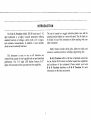
INTRODUCTION.
SPECIFICATIONS.
. Inside Front Cover
.......I
Page
C u r r e n t M e a s u r e m. e. .n t s
ResistanceMeasurem
. . e. n t s
ContinuityTesting
D i o d e T e s t i n. .g.
..........9
.......9
....10
....10
.......2
OPTIONALACCESSORIES...
.........5
CONTROLSANDINDICATORS
......,.6
CONTROLSANDINDICATORS
........7
OPERATINGINSTRUCTIONS..
Preliminary
VoltageMeasurements
........8
.....8
........8
M I { T N T E N A N C.E .
huseReplacement
lineVoltageSelection
f,estleads
InstrumentRepairService
...... II
....11
.......12
.....12
.....12
W A R R A N T YS E R V I C E I N S T R U C T I O N S . .
.....14
LIMITEDONE-YEARWARRANTY.... .......15
INTRODUCTION
The B & K Precision Model 28318 bench-type3-ll2
digit multimeter is a highly versatile instrument offering
standard functions of voltage, current (with a 20 A range),
and resistancemeasurements.[n addition, it also includes
diode test and continuity functions.
The instrument is easy to use, as all functions are
selectedfrom a panel of very logically laid out and identified
pushbuttons. The 3-ll2 digit LED display features 0.43"'
digits with automaticminus sign and auto-zerocapability.
The unit is housed in a rugged, attractiveplastic case,and the
carrying handle doublesas a sturdy tilt stand.The tilt standcan
be folded on top of the instrument to allow stacking with your
other instrument.
Safety features include safety jacks, safety test leads, and
extensiveoverloadprotection,including a high energy fuse.
B & K Precision offers a full line of optional accessories
for the Model 28318 which can further expand the capabilities
and usefulnessof the instrument. Please contact your locai
B & K Precision distributor or B & K Precision for more
information on the latestaccessories.
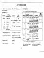
SPECIFICATIONS
All accuracies
specifiedat23"C + 5 oC,757omaximum
relative humidity.
TRIIE RMS: FROM lE/o tD 10V/oOF RANGE
DC VOLTAGE
RANGE
200mV
MAXIMUM
INDICATION
t199.9mV
2V
1 1 . 9 9 9V
20v
+ 1 9 . 9V
9
200v
1200v
1 1 9 9 . 9V
AC VOLTAGE
ACCURACY
MAX
INPUT
750V
(dc+ac
peak)
!(O.1o/oof reading
+ 1 count)
All ranges
1200v
I/IAXIMUM
RANGE INDICATIONFREQENCY
200mV
2V
50 dB minimum at 50160Hz.
Common mode rejection:
120 dB minimum at dc and
50160Hz with I kO unbalance.
I second.
Input Impedance:
10 MO.
4or-tsb1Kt-b(0.5% of rdg+acnbl
1KFLto10KJ-L(2/o of tdgr<q6;
10Kt-tsb20Klb(5% oftdg+4cnts)
20K]-tsb40KlE
(1ry0 of rdq+4cnb)
20v
Normal mode rejection:
ACCRACY
4oFtsb 1Kl-Et(0.5% of tdg+46651
1KFtsb10Kt-Et(2% ofrdg+acnbl
10Klkb20Klh t(5% of tdg{'4cnb1 750V rms
nrcb.b&Ki t(1flo ofrdg+46651
1.gSSV
(dc+ac peak)
11200v
Max.Input
Responsetime:
'199.9mV
MAX
INPUT
VOLTAGE
200v
't9.99V
4oFtsb l Klh t(0.5% of rdg+4cnb)
1Khtrtc10KFL{2% of rdg+acnbl
10Kl-tsb20KI-L
t(5% of tdg+466;
20Kl-tsb40KlLt(ltrlo of rdg+4665;
1000V rms
199.9/ 40 Flzto 1 KHz t(0.5% of tdg+acnt)
1 KFlzto10Kl-lzt(2% ofrdg+4cnts;
1000v A0tLlo 1lG-lz{0.5% of rdg+ cnb)
Max.Inpul
*Notto exceedthe Volt-Her?uoduct
ptoduclof
1000v
Inputimpedance.
10 MClin parallelwith
100pF.
Commonmoderejection: 60 dB minimumat 5060 Hz.
Responsetime:
3 secondsmaximum.
SPECIFICATIONS
AC CURRENT
DC CTIRRENT
RANGE
MAXIMUM
INDICATION ACCURACY
200 uA
1 1 9 9 . 9u A
2mA
t 1 . 9 9 9m A
20 mA
200 mA
2000mA
204
t19.99mA
L(0.2%of reading
+ 1 count)
MAXIMUM
INPUT
2A
TRUE RMS: FROM lUY" ta ljV/o OF RANGE
MAXIMUM
MAXIMUM
RANGE INDICATIONFREQUENCY ACCURACY
INPUT
200 pA
1 9 9 . 9p A
40Hzto 10KHz t(1% ofrdg+4cnb'
10KHzto 20KHz {2% ofrdg+acnE'
2mA
1.999mA
40Hzto10KHz {1% of tdg+4orb)
t(2% ofrdg+4cnb)
1OKFlzto20KHz
20 mA
19.99mA 40Hzto1OKHz t(1% oftdg+4cnb;
lOKHzto20KHz t(2% ofrdg+acnbl
200 mA
199.9mA 40Hzto10KHz t(1% ofrdg+qcnS)
1OKHzto 20KHz {2% of rdg+4cr"ts)
t199.9mA
t1999 mA
1 1 9 . 9 9A
r(0.3%of reading
20Athrough
+ 1 count)
20 A inputiaqk
Maximum burdenvoltage:
(with supplied
test leads)
0.3 V at 200 mA.
I V at 2000 mA.
2.5 Y (0.25V across20A
jacks) at 20 A.
Responsetime:
I second.
Overloadprotection:
2 N250 V fusein
serieson mA inputjack.
20 A rangeunfused.
2000mA
204
2A
1999mA 4OHztoZKHz (1% ofrdo+4cntsl
20Ahrough
19.99A 4OHzto2KHz t(1%ofrdg+acnts;
Z0Ainputiac*
Maximum burdenvoltage:
(with supplied
test leads)
0.3 V at 200 mA.
1 V at 2000 mA.
2.5 V (0-25V across20A
jacks) at 20 A.
Responsetime:
3 second.
Overloadprotection:
2 N250 V fusein series
on mA inputjack. 20 A
ranseunfused.
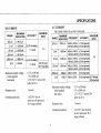
SPECIFICATIONS
RESISTANCE
GENERAL SPECIF'ICATIONS
MAXIMUM
RANGE NDICATION ACCUR,ACY
200o
199.9c)
2Kl)
1.999KC)
20 Kf)
19.99
Kc)
200Kc)
199.9KC)
1 (0.2%of rdq+2cntsl 4 . 2 m 4
42OuA
{0.2% of rdg+1cnt)
19.99Mo
42 uA
4.2uA
2000Kc) 1999Kc)
20MO
TEST OVERLOAD
SURRENT
PROTECTION
Temperaturerange:
Operating:
Storage:
450 V
dc/ac rms
All ranges
90%omaximum to +3511. except
80oZmaximum on 2000 k O and
20 M O range.70Yomaximum
to +40t (non-condensing).
Maximum common
mode voltage:
500 v'
Display:
LED, 0.43" characterheight.
Power requirements:
100/120/2201240
Y, 50160Hz,
t (0.5%of dq+1cnts) 0.042uA
5 V maximumloaded
r4ueuwith
wrtl
l0 M e
Responsetime:
3 second( 20 secondson
20 MO range)
DIODE TEST
Testedon 2 Kf) range.
-20"C to +60'C.
Humidity range:
0.42uA
open circuitvolage:
0'C to +40t.
5W.
([xHxD):
Dimeensions
261x 7t x 2l l mm
(10.21x 2.j9 x 8.3) in
I mA testcurrent.
CONTINUITY
weight:
r.63 Kg (3.6 lbs).
Audio tone soundswhen resistanceis lessthan l0 ohms
typical.
Accessoriessupplied:
Test leads(2)
Instructionmanual(l)
Spare2Atuse(2)
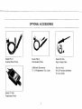
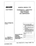
OPTIONALACCESSORIES
Model PR-21
Isolatior/Direct Probe
Model PR-23
DemodulatorProbe
I
I
AdditionalAf cessories
:
TL-2A Replacement
TestLeads
Model TP-30B
Temoerature Probe
Model PR-28A
High-voltageProbe
Seeyour local
B & K Precisiondistributor
for more details.
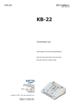
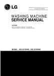
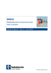
GONTROLSAND INDICATORS
l. V-O Jack Inputjack for volhge measuremen!resistance
measurement.Diode test and continuity test.
2. COMmon Jaclc Input forcommontest leadfor all
measuremeffs.
3. mA Jack
4. 20 A Jack
Input for200 pA to 2 A dc or ac currentranges.
Input for 20 amp dc or ac curent range.
5. AC/DC Switch. Selectsac or dc in voltageand current fimctions.
Engageswitch (set to "in" position) for ac; disengage(set to',ouf'
position) for dc.
6. V Switch.
Selectsvoltage fi.rnction.
7. A (amp) Switch. Selectscurrent firnction.
8.
O Switch. Selects diode test finction, resistance
)F )
firnctions, and continuity test fi.mction.When both 200 O and 2 K
resistance fi.nction are selected, this switch enables audible
continuity test. Continuity tone is enabled when switches are
engaged.
g. 2MmY/200pN200CU +f
r)) Switch. Selecrs200mV
range for acldc voltage functions, 200pA range for acldc
current functions, and 200 C) range for resistancefunction.
Enables continuitytestin conjunctionwith switch(8) and (10).
rc.zVnmA KCy iF
Switctr. Selects2 V rangefor acldcvoltage
finctions. 2 mA rangefor acldc currentfi.urctions,and 2 Kf) range
for resistancefirnction.Also selectsdiode test ( tF ) function.
ll . 20 V n0 mA/20 I(O Switch. Selects20 V rangefor ac,/dc
I voltage finctions. 20 mA rangefor ac,/dccurrent fimctions,and
20 K,f2 rangefor resistancefunction.
12.200 VD00 mAn00 KC) Switch. Selects200 V range for ac/dc
voltage functions.200 mA rangefor addc ctnrent finctions,
and 200 Kf) rangeforresistancefunction.
13.1200VDC/1000 VAC2000 mA/2000KQ Switch. Selects
1200V rangefor dc voltagefunction, 1000V rangefor ac voltage
firnctiorl 2000 mAQ A) rangefor acldc currentfi-rnctions,and
2000 Kf) (2 Mf)) rangeforresistancefunction.
4.20 AnI MQ Switch. Selects20A rangefor acldc currentfi.mctions. Used in co4junctionwith 20 Ajack (a). Also selects20 MC)
rangefor resistancefrmction
15.POWER Switch. Tums instument ON and OFF. Power-onindicatedby presenceofcharacterson display.
16 Display. 3-ln dlgtLED display wifh automaticdecimalpoint
and mimrs C) sigr. Indicatesto 1999counts.Over rangeindicated
by a "1" displayedat the lefonost digit while all other digits rernain
blank
CONTROLSAND INDICATORS
+t.8"'8.8.
Y/o/->/"0
7
B 9
Fig. 1. Controls and indicators
,7
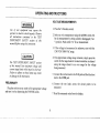
OPERATINGINSTRUCTIONS
VOLTAGE MEASUREMENTS
Use of test equipment mqy expose the
operator to electric shock hazards. Observe
all instructions contained in the TEST
INSTRUMENT SAFETY section of this
manual Before using this instrument.
l. Pressthe V function switch.
2. Selectac or dc measurementusing the AC/DC switch. Set
for dc nreasurementby setting switch to disengaged("out
") position.
Pushswitch "in" for ac measurement.
3. If the voltage to be measuredis unknown, start with the
1200VDC/I000 VAC range.
The TEST INSTRUMENT SAFETY section
of this manual lists maximum voltage and
current input limits which must be observed.
Failure to adhere to these limits may result
in damage to the instrument.
PRELIMINARY
Plug the unit into an ac outlet of the appropriatevoltage
and turn it on by depressingthe POWER switch.
4.lf an approximatevoltagerangeis known, simply pressthe
switch for the range desired. Greatestresolution is attained
using the range closest to an over range for the voltage
being measured.
5. Connectthe red test leadto the V-O jack and the black test
lead to the COM jack.
6. Connect the test leads across the circuit noints to be
measured.
7. Read the measuredvalue from the display.
OPERATINGINSTRUCTIONS
CURR E N M
T EA S U R E ME N T S
For current meqsurements,the meter must
be connected in series wilh the load. If
incorrectly connected (in parallel with the
load), the meter presents a very low
impedance (almost a short), which may blow
the fuse or damage the meter or equipment
under test. The 20 A range has on fuse
protection and moy severely damage the
meter or equipment under test or cause
personal injury.
For current meesurementsgreater thun 2 A,
high curent test leads should be used. High
current measurements with standard test
leads could cause the leads to heat up. This
nol only affects the accuracy of the
meqsurement, but could result in injury to
the operator.
1. Pressthe A function switch.
2. Selectac or dc measurementusing the AC/DC switch. Set for
"out" position. Push
dc measurementby setting switch to
"in"
for ac measurement.
switch
3. If the current to be measuredis unknown. start with the meter
in the 20 A range,using the 20 A jack. If the expectedcurrent
might exceed2 A, use high current test leads.
s
4.lf m approximatecurrent range is known, simply press the
switch for the rangedesired.Greatestresolutionis attainedusing
the rangeclosestto an overange for the current being measured.
a. For current measurementsof 2 A or less,connect the red test
leadto the 2 A jack and the black test lead to the COM jack.
greaterthan2 A, connectared high
b. For curent measurements
current test lead to the 20 Ajack and connectablack high
cuftent testlead to the COM jack.
5. Remove power from the circuit rurdermeasurementand openthe
normal circuit path where the measurement is to be taken.
Connectthe metsr in serleswith the circuit.
6. Apply porverto the circuit and read the measuredvalue on the
display.
MEASUREMENTS
RESISTANCE
L Remove power from the equipmentunder test.
2. Pressthe fJ function switch.
3. Connect the red test lead to the V -O jack and black test
lead to the COM jack. The red lead is (+) polarity.
4. Connectthe test leadsto the desiredpoint of measurement
and observethe readingon the display.
5. If the expectedresistancerange is unknown, start with the
lowest range. If an overrange is indicated, continue
selecting higher ranges until the overrange indication
ceases.At this range,greatestresolutionis achieved.
O PE R A T I N GI N S T R U C T ION S
CONTINUITYTESTING
DIODETESTING
l. Remove power from the equipmentundertest.
1. Pressthe Q switch.
2. Pressthe O switch.
2. Pressthe 2 K switch.
3. Select both 200 Q and 2 KC) resistanceranges (press both
200 and 2 K switchessimultaneously).
3. Connectthe red test lead to the V -fi jack and the black test
lead to the COM jack. The red lead is (+) polarity. The meter
usesconventional-currentleadpolarity for diode testing (i.e.
current flow assumedfrom positive-to-negative).
4. Connectthe red test lead to the V -Ojack and the black test
lead to the COM jack. The red lead is (+) polarity.
4. To check diode forward voltage(Vr), connectthe red test leadto
the anode and the black test lead to the cathode. Diodes and
semiconductorjunctions with normal V, of lessthan 2.0 V can
be checked.
5. Connectthe test leadsto the desiredmeasruementpoints.
6. If the resistancebetweenthe two points is less than 10 ohms
(tlpical), the continuity tone will sound.
7. Disengaging one of the two switches (200 O and 2 KC)
switch at "out" position) will disable the continuity tone.
The instrument will then be operating in standard ohms
mode.
5. The display indicates diode forward voltage. Normal diode
voltagesare approximately0.3 V for germaniumdiodes,0.6
V for silicon devices,and 1.6V for light emitting diode (LED's).
An overrange indicates an open diode. A shorted diode reads
near0 V.
6. To checkthe reverse-bias
conditionofa diode,reversethe testlead
connectionsto the device. The readingshould be the sameas with
open test leads (an overrange). A lower reading indicates a
leakydiode.
l0
MAINTENANCE
GurrentRangeFuse
Note: The fuse most likely to open first can be inspectedand
changedwithout caseremoval. It is locatedon the rear panel of
the unit. Simply use a flat blade screwdriver to rotate the
terminalcounterclockwise.
The following instructions are for use by
qualified service personnel only. To avoid
electrical shock, de not perform servicing
other than contained in the operating instructions unlessyou are qualified to do so.
Remember that ac line voltage is present on
line voltage input circuits any time the instrument is plugged into an ac outlet, even if
turned off. Always unplug the unit before
perforning servicing procedures.
Then remove the entire assembly,including the fuse. If this fLse is
blown, replace it with the appropriate2 A,250 V, 5 x 20 mm fastblow firse @art number 196-300-2-000). Then replace the
fineholder.
l
I
!
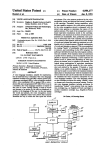
PowerSupplyFuse
If your unit does not operate at all (no digits lit), check power
supply fi4e (See Fig. 2) . Note: This fuse should not open unless
FUSE REPLACEMENT
some defect occurs in the instrument, Replace it only after
There are two fuses in the unit - one for the mA current investigation of the reasonfor its opening.Use the appropriatevalue:
range and one for the main power supply. If your unit continpes 0.25 A, 250 V, fast-blow Sart number 196-300-0-250) for
to operate(digits lit) but fails to measurecurrent, check the two 100/120V operatiorl or 125 mA, 250 V, fast-blow (part number
current fuses.
I 96-300-0-I 25\ for 220/240V operation.
.
ll
MAINTENANCE
TEST LEADS
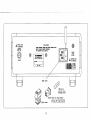
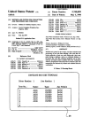
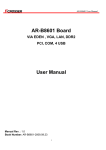
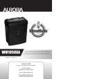
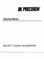
LINE V9LTAGE SELEGTI9N
charge fuse.
Periodically examine the test leads to ensure that the
conductorsare not intermittentor broken..Also make surethat
good contactpressureexists at the test lead receptacles.Keep
these areas free from dirt and corrosion. Use shrouded safeW
type replacementtest leads.
l.
Extract the tuse drawer from the AC socketwith the aid
INSTRUMENT
of a screwdrive(The extra safe fuse drawer can only be
Becauseof the specializedskills and test equipment required
for inskument repair and calibration' many customers prefer to
rely upon B & k Precision for this service. We maintain a
network of B & K Precision authorized service agenciesfor
this purpose. To use this service, even if the instrument is no
longer under warranty, follow the instructions given in the
WARRANTY SERVICE INSTRUCTIONS section of this
is a nominal charge for instruments out of
T;;Xl*.tn"re
This instrumentis the universal line operation: 100V, 120V,
220y and240v. The below is explaining the user how to
'
.
extracted with the aid of a flat blade scre\4'qrlver')
2.
Pull out the fuse from the fuse holder and chargethe fuse
rating in accordancewith specific required'
3.
Plugging fuse holder into the Line voltage indication
shown on the fuse drawer is correct. Rotating the fuse
holder before insert fuse drawer to have correct voltase
indication.
4.
Install the fuse drawer into AC sollect.
t2
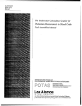
REPAIR SERVICE
n ru'trff Fust
lB
6 996p159
O,|intfI
r'UI FIJST
,/:\
l r
i \ l
t\,4'I
CAUTION
tLi ls oscol|rffi PilER cso BEF0RIRtuo\,$6covER
RtrtR r0 ol{rnD $Fllct Fttsofn€r..
llrs EouFil€r{rLJsT tr[rHED.
r
I
\=/
n RfPuct FUst
GL 6 5pgggl5p
2 25(ry
"e
u"
-'A
Mlll
v1c1ru""
(B)Fusedrorer
l3
(D)Fuse
rink
Fhln'eiusel
Holder rilh voltoge selector
Iiio.qe-ncPowersource|
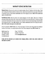
WARRANTYSERVICEINSTRUCTIONS
Warranty Service: Pleaseretum the product in the original packaging with proof of purchaseto the below address.Clearly
state in writing the performance problem and retum any leads, comectors and accessoriesthat you are using with the device.
Contact B&K Precisionto obtain a Return Authorization number before shipping the product to B&K. The RA number must
appear on the addresslabel.
Non-Warranty
Service: Return the product in the original packaging to the below address. Clearly state in writing the
performanceproblem and return any leads,connectorsand accessoribs
that you are using with the device.Customersnot on open
account must include payment in the form of a money order or credit card. For the most current repair chargescontact the factory
before shipping the product. Contact B&K Precision to obtain a Rdturn Authorization number before shipping the product to
B&K. The RA number must appear on the addresslabel.
Return all merchandise to B&K Precision Corp. with pre-paid shipping. The flat-rate repair charge includes return shipping to
locationsin North America. For overnight shipmentsand non-North America shipping feescontactB&K Precision Corp..
B&K Precision Corp.
1031 Segovia Circle
Placentia, C492870
www.bkprecision.com
Phone: 714-237-9220
Facsimile: 714-237-9214
Email: [email protected]
Include with the instrumentyour complete return shipping address,contact name, phone number and
descriptionof problem.
l4
WARRANTY
LTMITED
ONE-YEAR
B&K Precision Corp. warrants to the original purchaser that its product and the component parts thereof, will be free from
defects in workmanship and materials for a period of one year from the date of purchase.
B&K Precision Corp. will without charge, repair or replace, at its' option, defective product or component parts. Returned
product must be accompaniedby proof of the purchasedatein the form a salesreceipt.
To obtain warranty coveragein the U.S.A., this product must be registeredby completingand mailing the enclosedwarranty card
to B&K Precision Corp., l03l SegoviaCircle, Placentia,CA92870 within fifteen (15) days flom proof of purchase.
Exclusions: This warranty does not apply in the event pf misuse or abuse of the product or as a result of unauthorized
alternations or repairs. It is void if the serial number is qlternated, defaced or removed.
B&K Precision Corp. shall not be liable for any consequintial damages,including without limitation damagesresulting from
loss of use. Some statesdo not allow limitation of incidentalor consequentialdamages,so the above limitation or exclusionmay
not apply to you.
This warranty gives you specific rights and you may have other rights, which vary from state-to-state.
15
TESTINSTRUMENT
SAFEW
(continued from inside front cover)
8. Keep "one hand in the pocket" while handing an instrument probe. Be particularly careful to avoid contacting a nearby
metal object that could provide a good ground rehrrn path.
9. When using a probe, touch only the insulatedportion.Never touch the exposedtip portion.
"hot chassis"type. This
lO.Someequipmentwith a two-wire ac power cord, including some with polarizedpower plugs, is the
includes most recent television receiversand audio eqgipment.A plastic or wooden cabinet insulatesthe chassisto protect
the customer. When the cabinet is removed for servicipg, a serious shock hazard exists if the chassis is touched. Not only
does this present a dangerousshock hazard, but damaggto test instruments or the equipment under test may result. To make
measurementsin "hot chassis" equipment, always cofflect an isolation transformer between the ac outlet and the equipment
under test. The B & K Precision Model TR-l10 or l6Q4 Isolation Transformer,or Model 1653 or l655AC Power Supply is
"hot chassis"unlessyou
suitable for most applications.To be on the safe side, peat all two-wire ac powered equipmentas
are sure it has an isolated chassisor an earth ground chtissis.
l1.B & K Precision products are not authorizedfor use in any application involving direct contactbetween our product and
"direct contact" refers to any
the human body, or for use as a critical component in ja life support device or system. Here,
"critical
component of a life support device or
connection from or to our equipment via any cabling op switching means.A
system whose failure to perform can be reasonably expectedto cause failure ofthat device or system, or to affect its safety
or effectiveness.
l2.When testing ac powered equipment,rememberthat aq line voltage is usually presenton some power input circuits such as
on-off switch, fuses, power transformer, etc. any time the equipment is connectedto an ac outlet, even if the equipment is
tumed off.
13.Neverwork alone. Someoneshould be nearby to renderaid if necessary.Training in CPR (cardio-pulmonaryresuscitation)
first aid is highly recommended.
PAtr:481-316-9-001
Printedin Taiwan
@ 19998&KPrecisionCorp.
1031Segovia
Circle
Placentia,
CA 92870-7137
USA
TEL:714-237-9220
F pd,.714-237-9214
www.bkprecision.com