1
http://www.lgservice.com
N
LG PACKAGED
TERMINAL
AIRCONDITIONER/HEAT
PUMP
@
OWNER'S MANUAL
Please read the operating instructions and safety precautions carefully
and thoroughly before installing and operating your air conditioner.
=ins valuable
:This manual
proper
improper
FOR YOUR RECORDS
Write the model and serial numbers
here:
Model #
Serial #
You can find them on a label on the side of each unit.
Dealer's
Name
Date Purchased
• Staple your receipt to this page in the event you need it
to prove date of purchase or for warranty issues.
READ THIS MANUAL
Inside you will find many helpful hints on how to use and
maintain your air conditioner properly. Just a little
preventive care on your part can save you a great deal of
time and money over the life of your air conditioner.
You'll find many answers to common problems in the chart
of troubleshooting
tips. If you review our chart of
Troubleshooting
Tips first, you may not need to call for
service at all.
PRECAUTION
• Contact an authorized service
maintenance
of this unit.
• Contact
technician
the installer for installation
for repair or
of this unit.
• The air conditioner
is not intended for use by young
children or invalids without supervision.
• Young children should be supervised
to ensure
they do not play with the air conditioner.
that
• When the power cord is to be replaced, replacement
work shall be performed by authorized personnel
only using only genuine replacement
parts.
• Installation work must be performed in accordance
with the National Electric Code by qualified and
authorized personnel only.
2
Room Air Conditioner
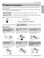
Safety
Precautions
To prevent injury to the user or other people and property damage, the following instructions
must be followed.
• Incorrect operation due to ignoring instruction will cause harm or damage. The seriousness
is classified by the following indications.
,j WARNING
CAUTION
This symbol indicates the possibility of death or serious injury.
Eg@
"N_2a
:L&
(
This symbol indicates the possibility of injury or damage to properties only.
\
• Meanings of symbols used in this manual are as shown below.
Q
Don't do this!
Be sure to follow the instruction,
A kWARNING
• Installation
• It may cause a fire or electrical
shock.
• It may cause failure and
electric shock.
• It may cause a fire or electrical
shock.
• Sharp edges may cause
injury.
• It will cause electric shock or fire
due to heat generation.
• It may cause explosion or fire.
Owner's
Manual
3
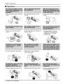
Safety
Precautions
• Operation
• There is danger of fire or electric
shock.
• An overloadedcircuit is a fire
hazard.
• It may cause fire and electric
shock.
• It will cause failure of machine or
electric shock.
• It may cause a fire or electrical
shock.
• The appearance of the air
conditioner may deteriorate,
change color, or develop
surface fla___
• It could represent a fire hazed.
• Otherwise, it may electrical
shock and failure.
/
0
/
• Oxygen depletion could occur.
4
Room Air Conditioner
• Moving parts could cause injury.
• Prevent accidental startup and
the possibility of injury.
Safety Precautions
@
• It will cause electric shock or fire
• It will cause electric shock or fire.
• It will cause electric shock.
due to heat generation.
®
®
• It may causeelectricshock and
damage.
• Otherwise, it may cause an
explosion and a fire.
• They are sharp and may cause
injury.
®
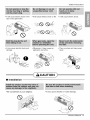
,_ CAUTION
• Installation
• Be considerate of your neighbor.
• It may cause vibration or water leakage.
Owner's
Manual
5
Safety
Precautions
• Operation
, It is notgoodto sit in thedraft.
° It may causeproductfailure.
° It maycausean injurythroughdropping ° Operation
without
filterswillcause
failure.
ofthe unit or falling down.
, The appearanceof theair conditioner
maydeteriorate,changecolor,or
developsurfaceflaws.
, It containseverycontaminant
condensedfromthe air andcouldcause
healthissues.
function
tocirculate . Electrical
° A severecutor otherinjurycouldresult. ° Usetheventilation
andmoving
partscouldcause
airwithoutcoolingorheating
, Thechemicalsinbatteriescouldcauseburnsor otherhealth
hazards.
shockor injury.
, Thechemicalsinbatteriescouldcauseburnsor otherhealth
hazards.
@
6
Room Air Conditioner
Be_ Ope_t_n
1. Contact an installation specialist for installation.
This is NOT a do-it-yourself project.
2. Plug in the power plug properly.
3. Use a dedicated circuit.
4. Do not use an extension cord. Consult a professional installer or electrician.
5. Do not start/stop operation by plugging/unplugging the power cord.
6. If the cord/plug is damaged, replace it with only an authorized replacement
part.
1. Being exposed to direct airflow for an extended period of time could be
hazardous to your health. Do not expose occupants, pets, or plants to direct
airflow for extended periods of time. In other words, don't sit in the draft.
2. Due to the possibility of oxygen deficiency, ventilate the room when used
together with stoves or other heating devices.
3. Do not use this air conditioner for non-specified special purposes (e.g.
preserving precision devices, food, pets, plants, and art objects). Such usage
could damage the items.
1. Do not touch the metal parts of the unit when removing the filter. Injuries can
occur when handling sharp metal edges.
2. Do not use water to clean inside the air conditioner. Exposure to water can
destroy the insulation, leading to possible electric shock.
3. When cleaning the unit, first make sure that the power and breaker are turned
off. The fan rotates at a very high speed during operation. There is a
possibility of injury if the unit's power is accidentally triggered on while
cleaning inner parts of the unit.
For repair and maintenance, contact your authorized service dealer.
Owner's
Manual
7
Introduction
This symbol alerts you to the risk of electric shock.
This symbol alerts you to hazards that could cause harm to
the air conditioner.
This symbol indicates special notes.
kWARNING
This appliance should be installed in accordance with the National Electric Code.
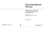
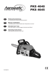
Expanded Metal Grille Should be applied for better performance in PTAC and PTHP Units.
For Installation purpose and better appearance Aluminium or Architectural grille can be applied in
PTAC and PTHP Units.
THE SLEEVE AND THE REAR GRILLE
(Available as an option)
VERTICAL AIR DEFLECTOR
(Horizontal Louver)
SLEEVE
ASSEMBLY
(IncludingAluminumRearGrille
REAR
GRILLE
(Aluminum Rear Grille)
(Air Intake)
EXPANDED
METAL GRILLE
(For Superior Performance)
LG PTAC and PTHP test condition
is recommended
metal grille
8
Room Air Conditioner
with expanded
Electrical
Safety
115V~
265V~
230V~
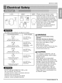
Power cord may include a current
interrupter device. A test and reset
button is provided on the plug case. The
device should be tested on a periodic
basis by first pressing the TEST button
and then the RESET button. If the TEST
button does not trip or if the RESET
button will not stay engaged,
discontinue use of the air conditioner
and contact a qualified service
technician.
The shape may be different according to its model.
Use Wall Receptacle
Power Supply
Use 15 AMP. time
Standard
grounding
208/230V,
receptacle
3-wire
delay fuse or 15 AMP.
Circuit breaker.
rated 15A
Use 20 AMP. time
delay fuse or 20 AMP.
Circuit breaker.
Standard
208/230V,
3-wire
grounding receptacle rated 20A
(2500W Heater _15AMP.
Circuit Breaker)
Use 30 AMP. time
Standard
grounding
208/230V,
receptacle
3-wire
delay fuse or 30 AMP.
Circuit breaker.
rated 30A
AWARNING
Never push the test button during
operation
Otherwise this plug can damaged,
This device contains chemicals, including
lead, known to the State of California to
cause cancer, birth defects, or other
reproductive harm.
Wash hands after handling.
Do not remove, modify, or immerse this plug.
If this device trips, the cause should be
corrected before further use.
A CAUTION
The conductors
Use 20 AMP. time
Standard 265V grounding
receptacle rated 20A
delay fuse or 20 AMP.
Circuit breaker.
These shields are not grounded.
Use 30 AMP. time
Standard 265V grounding
receptacle rated 30A
inside this cord are
surrounded by shields, which monitor
leakage current.
delay fuse or 30 AMP.
Circuit breaker.
Periodically examine the cord for any
damage. Do not use this product in the
event the shields become exposed.
Avoid shock hazard! This unit cannot
be serviced.
resistant,
DO NOT USE AN EXTENSION CORD on 230,
208, and 208/230, 265 Volt units.
Opening the tamper-
sealed portion of the unit
voids all warranties and performance
claims. This unit is not intended to be
an ON/OFF switch.
All wiring should be made in accordance with local
electrical codes and regulations.
Aluminum house wiring may pose special
problems. Consult a qualified electrician.
Owner's
Manual
9
Electrical
Safety
IMPORTANT
Ak CAUTION
(PLEASE READ CAREFULLY)
FOR THE USER'S PERSONAL SAFETY, THIS
APPLIANCE
MUST BE PROPERLY GROUNDED
The power cord of this appliance is equipped with a
three-prong (grounding) plug. Use this with a standard
three-slot (grounding) wall power outlet to minimize the
hazard of electric shock. The customer should have
the wall receptacle and circuit checked
electrician to make sure the receptacle
grounded.
by a qualified
is properly
Attaching the adapter ground terminal to the wall
receptacle cover screw does not ground the
appliance unless the cover screw is metal, and not
insulated, and the wall receptacle is grounded
through the house wiring. The customer should have
the circuit checked by a qualified electrician to make
sure the receptacle is properly grounded.
Disconnect the power cord from the adapter, using
one hand on each. Otherwise, the adapter ground
terminal might break. DO NOT USE the appliance with
a broken adapter plug.
DO NOT CUT OR REMOVE THE THIRD (GROUND)
PRONG FROM THE POWER PLUG.
A. SITUATIONS WHEN THE APPLIANCE
DISCONNECTED
OCCASIONALLY
WILL BE
Because of potential safety hazards, we strongly
discourage the use of an adapter plug. However, if you
wish to use an adapter, a TEMPORARY
CONNECTION
may be made. Use UL-listed adapter,
available from most local hardware stores.
B. SITUATIONS WHEN THE APPLIANCE
DISCONNECTED
OFTEN
WILL BE
Do not use an adapter plug in these situations.
Unplugging the power cord frequently can lead to an
eventual breakage of the ground terminal. The wall
power outlet should be replaced by a three-slot
(grounding) outlet instead.
The large slot in the adapter must be aligned with the
large slot in the receptacle to assure a proper polarity
connection.
USE OF EXTENSION CORDS
Because of potential safety hazards, we strongly
discourage the use of an extension cord. However, if
you wish to use an extension cord, use a CSA
certified/UL-listed
3-wire (grounding) extension cord.
10
Room Air Conditioner
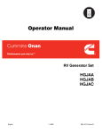
Installation
@
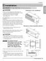
CAUTION
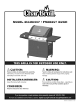
Dimension of air conditioner
• There are sharp edges that can cause serious cuts.
• If the unit is to be installed close to the seaside, it needs
additional treatment on the heat exchanger.
1,066 mm
• When lifting the air conditioner, it is HEAVY.
Use 2 people to lift.
For existing sleeve, you should measure the wall sleeve
dimensions.
(16")
You can install the new air conditioner according to these
installation instructions to achieve the best performence. All
wall sleeves used to mount the new air conditioner must be
in good structural condition and have the rear grille that
505 mm
securely attaches to the sleeve or the flange of the sleeve
to secure the new air conditioner.
Dimension of sleeve assembly (optional)
• To avoid vibration and noise, make sure the unit is
installed securely and firmly.
When installing the sleeve, make certain there is nothing
within 20" of the back that would interfere with heat
radiation and exhaust air flow.
A CAUTION
• Before installation, Check the insulation on the inner side
Joint Gap
of the sleeve. If there is no insulation, place the insulation.
• Check the bottom corner's joint gap of the sleeve, If there
.4
(121/2")
is, fill the gap with putty.
IfTt_'7/_
To maintain the best
performance of the LG PTAC,
an insulation strip must be
attached. The insulation strip
is provided with the box.
Refer to the diagram below.
EEvE H
A'R r"I
'NT_K:u
HEAT
H
b[le_==_
ofthelevel
*
B_AT'
_
ON
, Q_Ar_0"
_?\1
1) Take out the insulation strip from the upper packing.
280 mm
2) Attach the insulation strip onto the rear upper side of the
wall sleeve.
3) If anyone would like to improve unit energy efficiency, it
is recommended the change of outside grille for an unit
protection and an addition of a plastic rear grille. (This is
optional.)
_.
Front
Insulation
Strip
........
v
IV
Rear
Owner's Manual
11
Installation
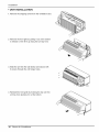
• UNIT INSTALLATION
1. Remove the shipping screw from the ventilation door.
2. Remove the front gille by pulling it out at the bottom
to release it, then lift it up along the unit top front.
3. Slide the unit into the wall sleeve andsecure with
6 screws through the unit flangeholes.
4. Reinstall the front grille by hooking the top over the
unit top, then pushing it in at the bottom.
12
Room Air Conditioner
Control
Locations
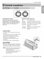
TEMPERATURE
OPERATION
MODE SELECTOR
Set the Thermostat control to the desired
CONTROL
OFF
Turns air conditioner off.
temperature mark 5 (the mid-point is a good
starting position). If the room temperature is not
satisfactory after a reasonable time, adjust the
control to a cooler or warmer setting, as
appropriate.
LOW FAN
Low speed fan operation without cooling.
HIGH FAN
High speed fan operation without cooling.
LOW COOL
Cooling with the low speed fan operation.
HIGH COOL
Cooling with the high speed fan
operation.
LOW HEAT
Heating with the low speed fan operation.
HIGH HEAT
Heating with the high speed fan
operation.
• VENTILATION
The ventilation lever is located to the lower left side
of the unit.
The ventilation lever must be in the CLOSE position in
order to maintain the best cooling conditions.
When fresh air is necessary in the room, set the
ventilation lever to the OPEN position.
The damper is opened and outdoor air is drawn
into the room.
This will reduce the cooling or heating efficiency.
CAUTION
When the air conditioner has been running and is
turned off or set to the fan position, wait at least 3
minutes before resetting to the cooling operation.
Note:
A slight heat odor may come from the unit
when first switching to HEAT after the
cooling season is over.
This odor, caused by fine dust particles on
the heater, will disappear quickly.
This is harmless.
Owner's Manual
13
Control
Locations
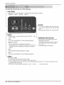
The controls will look like one of the following.
--FAN SPEED
• Every time you push this button, it cycles through the settings as follows:
{High(F2) , Low(F1) , High(F2) _ Low(F1)}
POWER
• To turn the air conditioner ON, push this button.
To turn the air conditioner OFF, push the button
again.
• This button takes priority over any other button.
- Pushthisbuttonto cyclethroughthemodesfromCOOL * FAN
• HEAT * COOL.
- COOL
• Fan runs continually for normal cooling operation.
- ENERGY SAVER
• The fanstopswhenthe compressorstopscooling.
Approximatelyevery3 minutesthefan willturn on andthe unit
will checkthe roomair temperatureto determineif coolingis
needed.
TEMPERATURESETTING
• Use this button to automatically control the
temperature of the room.
The temperature can be set within a range of
54° F(12°0)to 86 c F(30_C) by increments
of 2 ° F(I°C).
• The setting appears in the display.
- FAN
• Fan operation without heating or cooling.
- HEAT
• Fan runs continually for normal heating operation.
-TIMER
- SHUT-OFF
TIME
• You will usually use shut-off time while you sleep.
• If unit is running, use Timer to set number of hours until shut-off.
• For your sleeping comfort, once Time is set, the Temperature setting will raise 2 ° F(1 °C) after 30 minutes, and once
again after another 30 minutes.
• Push Timer to cycle through the settings from 1 Hour * 2 Hours * ... _ 12 Hours maximum.
14
Room Air Conditioner
Control
Locations
@
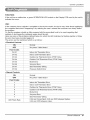
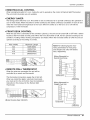
FUNCTION:
If the unit has a malfunction, a green OPERATION LED located on the Display PCB used by the unit to
indicate the errors.
USE:
If the customer has to register a complaint to the service center, he can be very clear about registering
the complaint that what is happening & by referring the user's manual the customer can clearly define
the problem.
So that the engineer should go fully prepared with the prescribed tools to be used regarding that
problem. It also keeps the customer aware about the unit.
Here are some of the problems defined below for which the LED indicates by flashing number of times
the error has been recorded against it.
The errors are the mentioned which is as follows:
• Electrical
Controls
ON
Normal
OFF
No power / failed board
Fault Codes
CH 01
Indoor Air Thermistor
CH 02
Indoor Coil Thermistor
Error
Error
CH 03
Outdoor Air Thermistor
Error (PTHP Only)
CH 04
Outdoor Coil Thermistor
CH 05
Mode Error
CH 06
Set point Error
CH 07
Bad Thermistor Wiring
CH 09
Pressure Switch Error
Error (PTHP Only)
• Manual Controls
ON
Normal
OFF
No power / failed board
Fault Codes
1
Indoor Air Thermistor
2
Indoor Coil Thermistor
Error
3
Outdoor Air Thermistor
Error (PTHP Only)
4
Outdoor Coil Thermistor
5
Mode Error
6
Set point Error
7
LED Flash Rate
Error
Error (PTHP Only)
Bad Thermistor Wiring
0.25 sec On per flash, 0.25 sec OFF between flashes,
2.00 sec OFF between codes.
Owner's Manual
15
Control
Locations
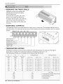
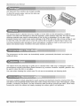
• REMOVING THE FRONT GRILLE
Additional
controls
are available
after
removing the front grille and option
cover of control box.
To remove the front grille,
pull out the
bottom of front grille and then lift up.
To replace
the front grille, place the tabs
over the top of the unit and push the
bottom of front grille
until the clips snap
into place.
• ADDITIONAL
The additional
the OFF
controls
position.
position.
CONTROLS
are located
behind the option
The authorized
REMOTE
ON
servicer
ON
ON
cover of control
has to check
switches
box. The standard
and ensure
settings
the switches
will be in
are in the desired
ON
ON
©
©
OFF
LOCAL OFF
1
2
Remote/Local _
I
Energy Saver
Temperature Limit 1Temperature Limit 2
Temperature Limit 3
PTAC/PTHP
UNITTYPE
• TEMPERATURE
Temperature
temperature
Limiting
16
OFF
5
can save money by limiting
The temperature
limiting
#3
Temperature
Limit 1
1
OFF
4
OFF
OFF
LIMITING
for heating.
This temperature
OFF
3
#4
Temperature
Limit 2
is not available
#5
Temperature
Limit 3
limiting
the lowest temperature
is controlled
with the Remote
for cooling
by switches
and the highest
#3 - #5.
Wall Thermostat.
Cooling Operation
Heating Operation
Lowest Temp.
Highest Temp.
Lowest Temp.
Highest Temp.
OFF
OFF
OFF
64° F (12.2 ° C)
86° F (30.0° C)
54° F (12.2° C)
86° F (30.0 ° C)
ON
OFF
OFF
66° F (13.3 ° C)
86° F (30.0° C)
54° F (12.2° C)
84° F (28.9 ° C)
OFF
ON
OFF
68° F (14.4 ° C)
86° F (30.0° C)
54° F (12.2° C)
82° F (27.8 ° C)
ON
ON
OFF
60° F (16.6 ° C)
86° F (30.0° C)
54° F (12.2° C)
80° F (26.7 ° C)
OFF
OFF
ON
62° F (16.6 ° C)
86° F (30.0° C)
54° F (12.2° C)
78° F (26.5 ° C)
ON
OFF
ON
64° F (17.7 ° C)
86° F (30.0° C)
54° F (12.2° C)
76° F (24.4 ° C)
OFF
ON
ON
66° F (18.9 ° C)
86° F (30.0° C)
54° F (12.2° C)
74° F (23.3 ° C)
ON
ON
ON
68° F (20.0 ° C)
86° F (30.0° C)
54° F (12.2° C)
72° F (22.2 ° C)
#6
#7
OFF
OFF
Cooling+Electric
Heater+Heat
OFF
ON
Cooling+Electric
Heater
ON
OFF
ON
ON
Room Air Conditioner
Unit Type
Heat Pump Only
Cooling
Only
Pump
Control
Locations
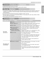
• REMOVING THE FRONT GRILLE
@
Additional controls are available after removing the
front grille and option cover of control box.
To remove the front grille, pull out the bottom of front
grille and then lift up.
To replace the front grille, place the tabs over the top
of the unit and push the bottom of front grille until the
clips snap into place.
• ADDITIONAL
CONTROLS
The additional controls are located behind the option cover of control box. The standard settings will be in
the OFF position. The authorized service man has to check switches and ensure the switches are in the
desired position.
REMOTE
ON
ON
ON
ON
LOCAL
OFF
OFF
OFF
OFF
2
3
4
ON
OFF
Remote/Local
Energy
_
Saver
--]
Temperature
Limit
1 --
Temperature
Limit
2
Temperature
Limit
3
• TEMPERATURE
LIMITING
Temperature Limiting can save money by limiting the lowest temperature for cooling and the highest
temperature for heating. The temperature limiting is controlled by dip switch #3 - #5.
This temperature limiting is not available with the Remote Wall Thermostat.
#3
#4
#5
Temperature
Temperature
Temperature
Limit#1
Limit#2
Limit#3
OFF
OFF
OFF
ON
OFF
OFF
OFF
ON
ON
CoolingOperation
Lowest Temp. Highest Temp.
HeatingOperation
Lowest Temp.
Highest Temp.
54°F (12.2°C)
86°F (30.0°C) 54°F (12.2°C)
86°F (30.0°C)
56°F (13.3°C)
86°F (30.0°C) 54°F (12.2°C)
84°F (28.9°C)
OFF
58°F (14.4°C)
86°F (30.0°C) 54°F (12.2°C)
82°F (27.8°C)
ON
OFF
60°F (15.5°C)
86°F (30.0°C) 54°F (12.2°C)
80°F (26.7°C)
OFF
OFF
ON
62°F (16.6°C)
86°F (30.0°C) 54°F (12.2°C)
78°F (25.5°C)
ON
OFF
ON
64°F (17.7°C)
86°F (30.0°C) 54°F (12.2°C)
76°F (24.4°C)
OFF
ON
ON
66°F (18.9°C)
86°F (30.0°C) 54°F (12.2°C)
74°F (23.3°C)
ON
ON
ON
68°F (20.0°C)
86°F (30.0°C) 54°F (12.2°C)
72°F (22.2°C)
Owner's Manual
17
Control
Locations
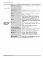
• REMOTE/LOCAL
CONTROL
When remote/local switch #1 is on, it allow the unit to operate by the Remote Wall Thermostat.
The unit control by knobs are not available.
• ENERGY SAVER
The energy saver switch #2 is on. This switch is set at cycle fan to provide continuous fan operation in cool
or heat modes. When the switch is off the continuous fan allows continuous circulation of room air and
make the more balanced temperature of the room. When the switch is on, the fan is on or off with the
compressor or with the heater.
• FRONT DESK CONTROL
When the pair wire is connected to the connector FD2 and FD1, the unit can be turned ON or OFF with a
switch located at the Front Desk Control panel. When the front desk switch is ON, the fan operates according
to the setting without working compressor and heater. When the front desk switch is OFF, the unit can
operate according to the setting of controls.
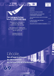
f
Wire # AWG
Motion
Motion
%
Maximum Length
Note: The following figures show wiring
#22
600 ft (180 m)
schematics for heat pump and straight cool
#20
#18
900 ft (270 m)
1500 ft (450 m)
units with electric heat, respectively.
#16
2000 ft (610 m)
Wiring Schematic for
Remote Heat Pump
Sensor
Sensor
G
Door
Switch
Front
Door
Desk Control
Switch
F,o.,oos_
(Molex Housing Spec 396-06V)
CONTROL
BOARD
G
CONNECTIONS
• REMOTE WALL THERMOSTAT
When the wires are connected, the unit will be controlled
by a remote wall thermostat.
The thermostat connections supply the 24 Volt AC. When
you install the digital/electronic thermostat, you must set it
to 24 Volt AC. See the installation Instruction in this manual
for the Remote Wall Thermostat.
THERMOSTAT
CONNECTIONS
Wiring Schematic for
Straight CoomUnit.
m
C
R
--
G
@
Y
W
O
GH
GL
CONTROL BOARD
CONNECTIONS
@
THERMOSTAT
CONNECTIONS
GL GH
0
W
Y
R
C
(Molex Housing Spec 396-07V)
18
Room Air Conditioner
Control
Locations
• REMOTE/LOCAL
CONTROL
@
When remote/local switch #1 is on, it allow the unit to operate by the control of Remote Wall Thermostat.
The unit control by knobs are not available.
• ENERGY SAVER
The energy saver switch #2 is on. This switch is set at continuous fan to provide continuous fan operation in
cool or heat modes. When the switch is off the continuous fan allows continuous circulation of room air and
make the more balanced temperature of the room. When the switch is on the fan is on or off with the
compressor or with the heater.
• FRONT DESK CONTROL
When the pair wire is connected to the connector LOand LI, the unit can be turned ON or OFF with a switch
located at the Front Desk Control panel. When the front desk switch is ON, the fan operate according to the
condition of setting without working compressor and heater. When the front desk switch is OFF, the unit can
operate according to the setting of controls.
Wire # AWG
Maximum Length
#22
600ft(180m)
#20
900ft(270m)
#18
1500ft(450m)
#16
2000ft(610m)
f
Note:The following figures show
wiring schematics for heat pump
and straight cool units with electric
heat, respectively.
Wiring Schematic for
Remote Heat Pump
I:! .......
I
®
• REMOTE WALL THERMOSTAT
When the wires are connected, the unit will be
controlled by a remote wall thermostat.
CONTROL BOARD
CONNECTIONS
The thermostat connections supply the 24 Volt AC.
When you install the digital / electronic thermostat,
you must set it to the 24 Volt AC. See the installation
Instruction in this manual for the Remote Wall
Thermostat.
--Q
THERMOSTAT
CONNECTIONS
Wiring Schematic for
Straight CoomUnit.
m
c
R
@
--
@
Y
w
GH
LO
U
GL
GH
O
W
Y
R
C
GL
(Molex Housing Spec 396-09V)
CONTROLBOARD
CONNECTIONS
Q
THERMOSTAT
CONNECTIONS
Owner's Manual
19
Control
Locations
- Before the following disassembly, POWER SWITCH is set to OFF and disconnected the power
cord.
1. Remove the front grille.
2. To remove the front grille, pull out the bottom of
the front grille and then lift up.
Re-install
the component
by referring to the
removal procedure.
3. To replace the front grille, place the tabs over
the top of the unit and push the bottom of front
grille until the clips snap into place.
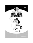
• This Room Air Conditioner
(PTAC) discharges
air from the top of the unit through
position discharge
reversible,
2-
grille louvers. The unit is
shipped from the factory with the discharge
40 °
grille
louvers at an angle of 40 ° off vertical. In an
alternate position the louvers will be at an angle
of 15 ° off vertical.
15 °
Screws
To adjust the air direction, remove the front grille.
Remove the 4 screws that fasten the discharge
grille to the front grille.
Flip the discharge
discharge
20
grille 180 °, then reattach
the
grille to the front grille with 4 screws.
Room Air Conditioner
Maintenance
andService
TURN THEAIR CONDITIONEROFF AND REMOVETHE PLUGFROMTHE POWEROUTLET.
The air filter should be checked at least twice a month to see if cleaning is necessary.
Trapped particles in the filter will build up and block the airflow. This reduces the cooling
capacity and also causes an accumulation of frost on the cooling coils.
If the filter becomes turn or damaged you should replace
immediately. Replacement
filters are available from your
salesperson, dealer, and the authorized customer service
centers.
1. Remove the air filter from the front grille assembly
pulling the air filter up slightly.
2. Wash the filter using lukewarm
by
water below 104 ° F(40°C).
3. Gently shake the excess water from the filter completely.
Replace the filter.
Before cleaning the vent filter, disconnect power to the
unit by unplugging the power cord at the wall outlet or
subbase, or disconnect power at the fuse box or circuit
breaker. If unit is operated with vent door closed, the
vent filter does not need to be cleaned.
1. Remove the cabinet front as described
Removal.
Figure A - Vent (Left side of unit)
in Front
2. Remove the six screws securing the chassis to the
wall sleeve with a Phillips-Head screwdriver.
3. Slide the chassis out of the wall sleeve far enough
so that the vent filter is accessible as shown in
Figure B - Vent Filter Removal
Figure A.
4. Remove the vent filter by unscrewing the two screws
at the top of the filter and gently pulling the filter
away from the partition panel. Refer to Figure B.
5. Clean and replace the filter by reattaching the hook
to the bottom of the vent door and replacing the two
screws, slide the chassis back into the wall sleeve,
secure it in place with six screws and reinstall the
front cabinet.
Owner's Manual
21
Maintenance
andService
The base pan may overflow due to high humidity.
To drain the excess water, remove the drain cap
from the back of the unit.
The chassis must be cleaned every four months or more often as the atmospheric conditions
require. Use water and detergent to clean the basepan, center partition and coils. The use of harsh
cleaning materials may cause a deterioration of the coil fins or endplates. Do not use a high
pressure cleaner as it could cause severe damage to the PTAC fins and coils. A hose is okay to use
to clean the coils, but make sure to cover the control with a blanket or plastic bag to keep it dry.
Corrosion Resistant units operating in harsh atmospheric conditions
sleeve and cleaned every 3 months in the same manner as above.
The compressor and fan motor are hermetically
additional oiling.
sealed, permanently
must be removed from the
lubricated,
and require no
The cabinet front and discharge air grille can be cleaned with a mild soap or detergent. Under no
circumstances should hydrocarbon based cleaners (e.g. acetone, benzene, naphtha, gasoline, etc.)
be used to clean the front or air grilles.
Use care when cleaning the control area. Do not use an excessively
wet cleaning cloth.
Corrosion resistant models subjected to harsh seacoast environments must be removed from the
wall sleeve and completely flushed with clean water at least four times a year. The basepan, center
partition, condenser end plates, and the condenser itself should be sprayed with clean, fresh water.
Leaving the unit in the sleeve and simply spraying the outdoor grille is not sufficient.
22
Room Air Conditioner
Maintenance
andService
Troubleshooting
Tips
save
time
andmoney!
Review
thechart
below
firstand
youmay
notneed
tocallforservice.
dut_<_
• You may hear a pinging noise caused by water being picked up and thrown by the slinger fan against the
condenser on rainy days or when the humidity is high. This design feature helps remove moisture and
improve efficiency.
• You may hear the thermostat click when the compressor cycles on and off.
• Water will collect in the base pan during high humidity or on rainy days. The water may overflow and drip
from the outdoor side of the unit.
• The fan may run even when the compressor does not.
• Check voltage
at outlet. Correct
if none.
• Check voltage to rotary switch. If none, check
supply cord. Replace cord if circuit is open.
power
• Check switch continuity. Refer to wiring diagram for
terminal identification.
Replace switch if defective.
• Connect wire. Refer to wiring diagram for terminal
identification.
Repair or replace loose terminal.
• Test capacitor.
Replace if not within +10% of manufacturer's
Replace if shorted, open, or damaged.
Fan motor
will not run.
rating.
• Fan blade hitting shroud or cross flow fan hitting
scroll. Realign assembly.
• Units using slinger
ring condenser
fans must have 1/4
to s/16 inch clearance to the base. If it is hitting the
base, shim up the bottom of the fan motor with
mounting screw(s).
• Check fan motor bearings;
rotate, replace the motor.
Fan motor
if motor shaft will not
runs
intermittently.
Owner's Manual
23
Maintenance
andService
Check
grommets;
if worn or missing,
If cracked, out of balance,
replace it.
Fan motor
noise.
Tighten
or partially
replace
them.
missing,
it.
• If knocking sounds continue when running or loose,
replace the motor. If the motor hums or noise appears
to be internal
while
running,
replace
Check voltage. See the voltage
limits, call an electrician.
motor.
limits. If not within
Check the wire connections,
if loose, repair or
replace the terminal. If wires are off, refer to wiring
diagram for identification,
and replace. Check wire
locations. If not per wiring diagram, correct.
Check for continuity, refer to the wiring diagram for
terminal identification.
Replace the switch if circuit is
open.
Compressor
will
not run, but fan
motor runs.
Check the position of knob If not at the coldest
setting, advance the knob to this setting and restart
unit.
Check continuity of the thermostat.
thermostat
if circuit is open.
Replace
Check the capacitor.
Replace if not within +10% of manufacturer's
Replace if shorted, open, or damaged.
rating.
Check the compressor
for open circuit or ground.
open or grounded, replace the compressor.
If
Check the compressor
overload, if externally
mounted. Replace if open. (If the compressor
temperature
is high, remove the overload, cool it,
and retest.)
Check continuity of the pressure switch.
pressure switch if circuit is open.
24
Room Air Conditioner
Replace
the
Maintenance
andService
@
Compressor
cycles
on
overload.
If restricted,
Insufficient
cooling
Close
or heating.
Excessive
clean or replace.
if open.
Determine
be cooled.
if the unit is properly
sized for the area to
Check the set screw or clamp. If loose or missing,
correct. If the blower or fan is hitting air guide,
rearrange the air handling parts.
noise.
Carefully rearrange tubing not to contact,
shroud, and barrier.
compressor,
ROOM AIR CONDITIONER VOLTAGE LIMITS
NAME
PLATE
RATING
208/230
265
V
V
MINIMUM
MAXIMUM
187 V
253 V
239 V
292 V
Owner's Manual
25
GARANTIE
LIMITI_E
Si le produit pr_sente un d_faut de mat&iaux ou de fabrication dans des conditions d'utilisation normales pendant _#,
la p_riode de garantie indiqu_e ci-dessous, laquelle p&iode de garantie est en vigueur glpartir de la date d'achat _::_A_;_
d'origine, LG Electronics r{parera ou remplacera, gtsa discretion, le produit sans frais.
>gclg#
La garantie est valide seulement pour l'acheteur d'origine du produit, pendant la p_riode de garantie, rant et aussi ::_#_
longtemps que cela soit au Canada.
>,z_
P_riode
de garantie
du climatiseur
LG
Composant
h_!% Toutes les pi_ces
Pii_ces
5 arts
Main-d'oeuvre
I arts (service '5 domicile)
_!_,_# Compresseur
5 arts
5 arts (service '5 domicile)
_
Aucune autre garantie n'est applicable fi ce produit. LA DURI_E DE TOUTE GARANTIE IMPLICITE, INCLUANT N?_
LA GARANTIE IMPLICITE DE COMMERCIALISATION, EST LIMITt_E A. LA DURt_E DE LA GARANTIE '-_;:,
¢.x5.
EXPRESSE INDIQUt_E CI-APRI_S. LG ELECTRONICS NE PEUT I_TRE TENUE RESPONSABLE POUR LA :_:?:_
_:_5;_ PERTE D'UTILISATION DE CE PRODUIT, INCONVI_NIENT,PERTE OU TOUT AUTRE DOMMAGE, DIRECT _i'_
_:'_'_ OU INDIRECTS, SURVENANT X LA sUITE DE L'UTILISATION OU DE L'INHABILITI_ X UTILISER LE
_v_ PRODUIT OU PoUR TOUT BRIS DE GARANTIE IMPLICITE OU EXPRESSE, INCLUANT LA GARANTIE
:_:/!_5_IMPLICITE DE COMMERCIALISATION OU A DES FINS PARTICULIERES, APPLICABLES A CE PRODUIT.
_:>,{_
:_>_,_
_
Certaines provinces ou territoires ne permettent pas l'exclusion ou la limitation de dommages indirects ou accessoires
_>
de limitation sur la dur& d'une garantie implicite, par consequent, ces limitations peuvent ne pas s'appliquer.
#,_:_: Cette garantie vous (l'acheteur d'origine) donne des droits sp_cifiques l_gaux et vous pouvez en avoir d'autres qui _-_,
>::_,,:_
_;_< varient d'une province ou territoire g_un autre.
,÷_
.....
>;a
LA GARANTIE SUSMENTIONNI_E NE S'APPLIQUE
PAS :
ii!,N
1. Au d0placement de service g_domicile pour livrer ou cueillir, installer, instruire ou remplacer un fusible ou _:'<;_
rebrancher le cgblage r&identiel ou la plomberie ou corriger une r_paration non autoris_e.
2. Aux dommages au produit causes par accident, vermine, incendie, inondation ou actes de Dieu.
)f!_g 3. Aux r_parations lorsque le produit LG est utilis_ gtdes fns autres que normales, utilisation r&identielle unilhmiliale :_,;_>_
ou contraire aux instructions donnOes dans le guide du propriOtairedu produit.
4. Aux dommages r_sultant d'accident, modifcation, mauvaise utilisation, abus ou installationou entretien inadOquat.
>>:v_74
5. Aux produits modifiOsou dont le numOrode sOriea _tOenle%.
2_'_! Si le produit est install_ 5 l'ext&ieur de la zone de service normale, tous frais de d_placement n_cessaire pour la 5_,i_
i:_¢_i_
_ r_paration du produit, ou le remplacement d'une piece d_fectueuse seront imput& au propri_taire.
INFORMATION
Pour obtenir une garantie :
Pour obtenir de l'aide sur le
ou pour le service h la clientlde :
Pour obtenir le centre de
service autoris_ le plus pri_s :
D'AIDE A. LA CLIENTELE
:
Conserver la facture comme preuve de la date d'achat.
Une copie de la facture doit &trepresent& lorsqu'un service sous
garantie est fourni.
Cette _arantie n'est pas valide si le num_ro de s6rie appos6 en usine
a _t_ modifi_ ou enlev_ du produit.
T414phoner au 1-888-LG-CANADA (542-2623)
Presser l'option du menu approprier, et avoir les num_ros de
module et de s4rie et votre code postal sous la main.
Aller au site web : www.LG.ca (option service) ou t_l_phoner au
1-888-LG-CANADA (542-2623)
Presser l'option du menu approprier, et avoir les num_ms de
module et de s&ie et votre code postal sous la main.
_5_:¢,#
Cv:"
_J
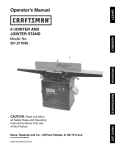
Should your LG Packaged Terminal Air Conditioner prove to be defective in materials or workmanship under normal use during
_
the warranty period listed below, LG Electronics will replace the defective part(s). Replacement part(s) will meet intended fit and
)_;_ function of the original part(s). Replacement parts are warranted for the unexpired portion of the original warranty period. This
_:_ii:_(warranty is good only to the original purchaser of the product and effective only when used in the United States
WARRANTY
#_:
7_4_;q
_iD
,_
77if_'
_'F;_
PERIOD:
For The Period Of:
LGE Will Replace:
_z
Irne_Yi;rdate of the
fAu_lY$$er.t
°faLrGEaPaac_agLGd
T]i_l inal which fails due to a defect in materials or w°rkmanehip During th's
-y
y,
' leo provide, free of charge, all labor and on-site service to replace
the defective part.
,'
_iI
original purchase
Five Years
_;;_;_J_ From
..... the date of the
__
original purchase
_
Any part of the sealed refrigerating system (the compressor, condenser, evaporator and all
connecting tubing) which fails due to a defect in materials or workmanship. During this full five-year
sealed refrigerating system warranty, LGE will also provide, free of charge, all labor and on-site
service to replace the defective part.
;>._;::/ FnveYears
g_5:_!_:From the date of the
_
!!_!_
original purchase
_4_;;
For the second through the fifth year from the date of original purchase. LGE will replace certain
:;:#
parts that fail due to a defect in materials or workmanship. Parts covered are fan motors, switches,
_:(i>
thermostats, heater heater protectors compressor overload, solenoids circuit boards auxiliary controls
thermistors, frost controls, ICR pump. capacntors,varistors and indoor blower bearing. During thus Inmnted
_S_'J_;_
_._
four-year parts warranty you will' be responsible for any labor or on-site service costs.
_!?!<#
_i_:Q_
/¢_
_?:_
No other warranty is applicable to this product. THIS WARRANTY IS IN LIEU OF ANY OTHER WARRANTY,
EXPRESS OR IMPLIED, INCLUDING WITHOUT LIMITATION, ANY WARRANTY OF MERCHANTABILITY OR FITNESS
FOR A PARTICULAR PURPOSE. TO THE EXTENT ANY IMPLIED WARRANTY IS REQUIRED BY LAW, IT IS LIMITED
IN DURATION TO THE EXPRESS WARRANTY PERIOD ABOVE. NEITHER THE MANUFACTURER NOR ITS U.S.
i;_._i)
'_
;_:>;
_:;!_
"_,iI_
DISTRIBUTOR SHALL BE LIABLE FOR ANY INCIDENTAL, CONSEQUENTIAL, INDIRECT, SPECIAL, OR PUNITIVE
DAMAGES OF ANY NATURE, INCLUDING WITHOUT LIMITATION, LOST REVENUES OR PROFITS, OR ANY OTHER
7;i_
_!i_;
_:)t_ DAMAGE WHETHER BASED IN CONTRACT, TORT, OR OTHERWISE. Some states and/or territories do net allow the
exclusion or limitation of incidental or consequential damages or limitations on hew long an implied warranty lasts, so
the above exclusion or limitation may net apply to you. This warranty gives you, the original purchaser, specific legal
rights and you may also have other rights that vary from state to state or territory to territory.
THIS
1.
2.
3.
4.
5.
6.
7.
LIMITED
WARRANTY
DOES
NOT APPLY
f:!!_
_,!3;+
d,_
_ik';iS
TO:
Service trips to your home for delivery or pickup, install, instruct or replace house fuses, or connect
house wiring or plumbing, or correction of unauthorized repairs.
Failure of product to perform during power failures and interruptions or inadequate electrical service.
Damage caused by transportation or handling.
Damage to the product caused by accident, vermin, lightning, winds, fire, floods, or acts of God.
Damages caused by leaky or broken water pipes, frozen water pipes, restricted drain lines, or
inadequate or interrupted water supply.
Damages cause by inadequate supply of air.
Damages resulting from running the product in a corrosive atmosphere.
8.
Damage resulting from accident, misuse, abuse, or improper installation, repair, or maintenance.
Improper repair includes use of parts not approved or specified by LG.
g. Normal maintenance as described in the installation instructions and use and care manual, such as
replacing filters, cleaning of coils, etc.
£2% 10. Use of accessories or components that are not compatible with this product.
1 1. Products with altered or removed serial numbers.
12. Changes in the appearance of the product that do not affect product performance.
13. Increases in utility costs and additional utility expenses.
_4_
The cost of repair or replacement under these excluded circumstances shall be borne by the consumer.
P/No. 3828A20255J
Printed in Korea