1
Owners
Manual
FOR POTABLE WATER
HEATING ONLY
NOT SUITABLE FOR
SPACE HEATING
COMMERCIAL
GAS WATER
NOT FOR USE IN
MOBILE HOMES
Model
No.
153.337002
153.337072
• Care and Maintenance
• Troubleshooting
• Parts List
• Safety Instructions
• Installation
• Operation
100 GaL
73 Gal.
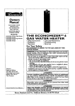
HEATER
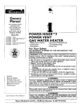
For Your Safety
AN ODORANT
IS ADDED
WATER HEATER
WARNING:
TO THE GAS USED
If the information
in these
lowed
exactly, a fire or explosion
damage, personal inlury or death.
BY THIS
instructions
may result,
are not fol-
causing
-Do not store or use gasoline or other flammable
in the vicinity of this or any other appliance.
-WHAT
TO DO IF YOU SMELL GAS
property
vapors and liquids
; Do not try to light any appliance.
Do not touch any electrical switch; do not use any phone in your
building.
i
Follow
the gascall
supplier'sinstructions.
mmediately
your gas supplier from a neighbor's
phone.
If you can not reach your gas supplier, call the fire department.
-Installation
and service must be performed
service agency or the gas supplier.
l
installer,
_E,WARNING
Improper
installation,
adjustment,
alteration,
I
service
or
maintenance
can I
cause DEATH, SERIOUS BODILY INJURY, OR PROPERTY DAMAGE. Refer to
this manual for assistance or consult the local Sears Service Center or gas utility for further information.
Caution:
Read and Follow
All Safety Rules and
Operating Instructions
Before First Use of
This Product.
Flammable
vapors may be drawn
by air currents
_WARNING
structure
to this appliance.
Save this Manual for Future Reference.
Sears,
by a qualified
Roebuck
from
other
READ THE GENERAL SAFETY SECTION
BEGINNING
ON
AND THEN THIS ENTIRE MANUAL
BEFORE
INSTALLING
•,WARNING
NG TH S WATER HEATER.
and Co., Hoffman
Estates,
IL 60179
U.S.A.
areas of the ]
INSIDE COVER
OR OPERAT-
I
Safety Precautions
J
AWARNING
]
Improper installatio_lteration,
service or I
maintenance
can cause DEATH,
SERIOUS
BODILY I
INJURY, OR PROPERTY DAMAGE. Refer to this manu- J
al for assistance or consult your local Sears Service
Center for further
nformat
on.
AWARNING
WATER HEATERS EQUIPPED
FOR ONE TYPE GAS
ONLY: This water heater is equipped for one type gas
only. Check the model rating plate near the gas control
valve for the correct gas. DO NOT USE THIS WATER
HEATER WITH
ANY GAS OTHER THAN THE ONE
SHOWN
ON THE MODEL RATING PLATE. Failure to
use the correct gas can cause problems which can result in
DEATH,
SERIOUS
BODILY INJURY, OR PROPERTY
DAMAGE. If you have any questions or doubts consult
your gas supplier or local utility.
_WARNING
INSTALLATIONS
IN AREAS WHERE FLAMMABLE LIQUIDS (VAPORS)
ARE LIKELY TO BE PRESENT
OR
STORED (GARAGES, STORAGE, AND UTILITY AREAS,
ETC): Flammable
liquids (such as gasoline, solvents,
propane (LP) or butane, etc.), all of which emit flammable
vapors, may be improperly stored or used in such areas.
The gas water heater pilot light or main burner can ignite
such vapors. The resulting flashback and fire can cause
death or serious burns to anyone in the area, as well as
property damage.
If installation in such areas is your only option, then the
installation must be accomplished in a way that the pilot
flame and main burner flame are elevated from the floor
at least 18 inches. While this may reduce the chances of
flammable vapors from a floor spill being ignited, gasoline
and other flammable substances should never be stored or
used in the same room or area containing a gas water
heater or other open flame or spark producing appliance.
NOTE: Flammable vapors may be drawn by air currents
from other areas of the structure to the appliance.
_,WARNING
If this water heater will be used in beauty shops, barber
shops, cleaning establishments, or self-service laundries
with dry cleaning equipment,
it is imperative that the
water heater or water heaters be installed so that combustion and ventilation air be taken from outside these
areas. Refer to the "Locating
The New Water Heater"
section of this manual and also the latest edition of the
National Fuel Gas Code, ANSI Z223.1, also referred to as
NFPA 54 for specifics provided concerning air required.
AWARNING
1
A fire can start if combustible materials such as clothing,|
cleaningmaterials, or flammable liquidsare placed against|
or next to the water heater.
|
AWARNING
At the time of manufacture this water heater was provided with a combination temperature-pressures
relief
valve certified by a nationally
recognized testing laboratory that maintains periodic inspection of production of
listed equipment or materials, as meeting the requirements for Relief Valves and Automatic
Gas Shutoff
Devices for Hot Water Supply Systems, and the latest
edition of ANSI Z21.22 and the code requirements
of
ASME. If replaced,
the valve must meet the requirements of local codes, but not less than a combination
temperature
and pressure relief valve certified as meeting the requirements
for Relief Valves and Automatic
Gas Shutoff Devices for Hot Water Supply Systems,
ANSI Z21.22 by a nationally recognized testing laboratory that maintains
periodic inspection of production of
listed equipment or materials.
The valve must be marked with a maximum set pressure
not to exceed the marked hydrostatic working pressure
of the water heater (150 Ibs./sq. in.) and a discharge
capacity not less than the water heater input rate as
shown on the model rating plate. (Electric heaters watts divided by 1000 x 3415 equal BTU/Hr. rate.)
Your local jurisdictional authority, while mandating
the
use of a temperature-pressure
relief valve complying
with ANSI Z21.22 and ASME, may require a valve model
different from the one furnished with the water heater.
Compliance with such local requirements
must be satisfied by the installer or end user of the water heater with
a locally prescribed temperature-pressure
relief valve
installed in the designated opening in the water heater in
place of the factory furnished valve.
For safe operation of the water heater, the relief valve
must not be removed from it's designated opening or
plugged.
The temperature-pressure
relief valve must be installed
directly into the fitting of the water heater designatedxf_;_.
the relief valve. Position the valve downward and provide
tubing so tha_any discharge will exit only within 6finches,
above, or at any dist:_ow-'_"_s_P_uc-Tur'P-_11o0r.
Be
certain that no contact_is.mad_e
e_ lect_ical"
_art. The discharge opening must not be blocked or
reduced
n s ze under-_an_es_Excess
ve
length, over 30 feet, or use of more than_four'e_lbows can
cause restriction and redu'_e-_-_--dffch'arge
capaLctty.-of
the valve.
,. - _ No valve or other obstruction is to b-e--I_lacec]-b_tween
the relief valve and the _k,-JDo-n_t
t_tibifig
directly to discharge drain unless a 6" air gap is provided.
To prevent bodily injury, I_r_rd t_fife,-or-property
damage, the relief valve must be allowed to discharge water
in quantities should circumstances demand. If the discharge pipe is not connected to a drain or other suitable
means, the water flow may cause property damage.
The Discharge Pipe:
• Must not be smaller in size than the outlet pipe size of
the valve, or have any reducing
couplings or other
restrictions.
• Must not be plugged or blocked.
• Must be of material listed for hot water distribution.
• Must be installed so as to allow complete drainage of
both the temperature-pressure
relief valve, and the
discharge pipe.
• Must terminate at an adequate drain.
• Must not have any valve between the relief valve and
tan_
Safety Precautions
_WARNING
AWARNING
A gas water heater cannot operate properly without the
correct amount of air for combustion. Do not install in a
confined area such a closet, unless you provide air as
shown in the "Locating The New Water Heater" section.
Never obstruct the flow of ventilation air. If you have any
doubts or questions at all, call your gas company. Failure
to provide the proper amount of combustion air can result
in a fire or explosion and can cause DEATH, SERIOUS
BODILY INJURY, OR PROPERTY DAMAGE.
This water heater must not be installed directly on carpeting. Carpeting must be protected by a metal or wood
panel beneath the appliance extending beyond the full
width and depth of the appliance
by at least 3 inches
(76.2mm) in any direction, or if the appliance is installed
in an alcove or closet, the entire floor must he covered by
the panel. Failure to heed this warning may result in a
fire hazard.
_,WARNING
•_ WARNING
VENT DAMPERS - Any vent damper, whether it is operated thermally or otherwise must be removed if its use
inhibits proper drafting of the water heater.
Thermally
Operated
Vent Dampers:
Gas-fired water
heaters having thermal efficiency in excess of 80% may
)roduce a relatively low flue gas temperature. Such tem)eratures may not be high enough to properly open thermally operated vent dampers. This would cause spillage of
flue gases and may cause carbon monoxide poisoning.
Vent dampers must bear evidence of certification as complying with the latest edition of American
National
Standard ANSI Z21.68 (ANSI Z21.66 & 67, respectively,
cover electrically
and mechanically
actuated
vent
dampers). Before installation of any vent damper, consult
your local Sears Service Center or the gas utility for further information.
HOTTER
WATER
CAN SCALD: Water heaters are
intended to produce hot water. Water heated to a temlerature which will satisfy clothes washing, dish washing,
and other sanitizing needs can scald and permanently
injure you upon contact. Some people are more likely to
be permanently injured by hot water than others. These
include the elderly, children, the infirm, or physicallylmentally handicapped. If anyone_sing hot water in your home
fits into one of these groups or if there is a local code or
;fate law requiring a certain temperature water at the hot
water tap, then you must take special precautions. In addition to using the lowest possible temperature setting that
satisfies your hot water needs, a means such as a mixing
valve, should be used at the hot water taps used by these
)eople or at the water heater. Mixing valves are available
at plumbing supply or hardware stores. Follow manufacturers instructions for installation of the valves. Before
changing the factory setting on the thermostat, read the
"Temperature
Regulation" section in this manual.
A, WARNING
• The appliance and its individual shutoff valve must be disconnected from _he gas supply piping system during any
pressure testing of the gas system at test pressures in
excess of I/2 pound per square inch (3.SkPa).
• The appliance must be isolated from the gas supply piping system by closing its individual manual shutoff valve
during any pressure testing of the gas supply piping system at test pressures equal or less than I/2 pound per
square inch (3.SkPa).
AWARNING
Soot build-up indicates a problem that requires correction before further use. Turn "off" gas to water heater
and leave "off" until repairs are made, because failure to
correct the cause of the sooting can result in a fire or
explosion.causing
DEATH, SERIOUS BODILY INJURY,
OR PROPERTY DAMAGE.
_,WARNING
AWARNING
Chemical vapor corrosion of the flue and vent system
may occur if air for combustion contains certain chemical
vapors. Spray can propellants, cleaningsolvents,refrigerator and air conditioner refrigerants,
swimming pool
chemicals, calcium and sodium chloride, waxes, bleach,
and process chemicals are typical compounds which are
potentially corrosive.
IEFORE
LIGHTING
[PROPANE
(L.R) GAS WATER
HEATERS]: Propane (L.R) gas is heavier than air. Should
there be a leak in the system, the gas will settle near the
ground. Basements, crawl spaces, skirted areas under
mobile homes (even when ventilated), closets and areas
below ground level will serve as pockets for the accumulation of this gas. Before attempting to light or relight the
water heater's pilot or turning on a nearby electrical light
switch, be absolutely sure there is no accumulated gas in
the area. Search for odor of gas by sniffing at ground level
in the vicinity of the appliance. If odor is detected, follow
steps indicated at "For Your Safety" on the cover page of
this manual then leave the premises.
Obstructed or deteriorated vent systems may
A. WARNING
present a
ser ous health risk or asphyxiation.
Safety Precautions continued on page 4
3
Safety Precautions
I
A, WARNING
]
The water heater wi_talled
must be prop- [
erly vented to a chimney which terminates
outdoors.[
Never operate the water heater unless it is vented to the[
outdoors and has adequate air supply to avoid risks of|
improper operation, explosion
I_fro
or asphyxiation.
_, WARNING
J
]
inimum clearances between the water heater and corn-|
ustible construction are I" at the sides and rear, 4 at the|
nt, and 6" from the vent pipe. Clearance from the top of the|
I jacket is 18 '. Refer to the label on the water heater adjacent to|
Ithe gas control valve for all clearances.
/
•_WARNING
Do not
water.
inspect
part of
use this appliance if any part of it has been under
Immediately
call a Sears Service Technician to
the appliance and to replace the gas control or any
the burner syster_ which has been under water.
_WARNING
HYDROGEN GAS: Hydrogen gas can be produced in a hot
water system that has not been used for a long period of
time (generally two weeks or more). Hydrogen gas is
extremely flammable and explosive. To prevent the possibility of injury under these conditions, we recommend the
hot water faucet be opened for several minutes at the
kitchen sink before any electrical appliances which are
connected to the hot water system are used (such as a
dishwasher or washing machine). If hydrogen gas is present, there will probably be an unusual sound similar to air
escaping through the pipe as the hot water faucet is
opened. There must he no smoking or open flame near
the faucet at the time it is open.
A, WARNING
INSULATING
JACKETS: When installing an external
water heater insulation jacket on a gas water heater:
DO NOT cover the temperature-pressure
relief valve.
DO NOT put insulation over any part of the top of the
gas water heater.
DO NOT put insulation over the gas control valve or gas
control valve/burner cover, or any access areas to the
burner.
• DO NOT let insulation around the gas water heater to
get within 8 inches of the floor (air must get to the
burner).
• DO NOT cover or remove operating instructions, and
safety related warning labels and materials affixed to the
water heater.
Failure to heed this will result in the possibility of a fire or
i explosion.
I
A, CAUTION
WATER HEATERS EVENTUALLY
LEAK: Installation of
the water heater must be accomplished in such a manner
that if the tank or any connections should leak, the flow of
water will not cause damage to the structure. For this
reason, it is not advisable to install the water heater in an
attic or upper floor. When such locations cannot be avoided, a suitable drain pan should be installed under the
water heater. Drain pans are available at your local Sears
store. Such a drain pan must be not greater than I I/2
inches deep, have a minimum length and width of at least
2 inches greater than the water heater dimensions and
must be piped to an adequate drain. The pan must not
restrict combustion air flow. Under no circumstances is
the manufacturer or Sears to he held liable for any water
damage in connection with this water heater.
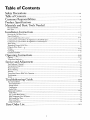
Table of Contents
Safety Precautions
.............................................................................................................
2-4
Table of Contents .......................................................................................................
5
Customer Responsibilities ........................................................................................
Product Specifications ..............................................................................................
6
Materials and Basic Tools Needed ...............................................................................................
7
Materials Needed ......................................................................................................................................................................
Basic Tools ................................................................................................................................................................................
7
7
Installation Instructions ............................................................................................
g-17
Removing the Old Water Heater ...............................................................................................................................................
Typical Installation ...................................................................................................................................................................
Facts to Consider About the Location ................................................................................................................................
Combustion Air and Ventilation for Appliances in Unconfined Spaces ...................................................................................
Combustion Air and Ventilation for Appliances in Confined Spaces ..................................................................................
Water Piping ...........................................................................................................................................................................
Temperature-Pressure Relief Valve...........................................................................................................................................
Filling the Water Heater......;/, ..................................................................................................................................................
Venting .......................................................................................................................................................
Gas Piping .........................................................................................................................................................................
Installation Checldist ..............................................................................................................................................................
Operating
Instructions
8
9
l 0-11
11
11-12
12
13
14
14-15
15-16
17
...................................................................................................
18-20
18 19
lighting .............................................................................................................................................................................
Temperature Regulation ..........................................................................................................................................................
-
20
Service and Adjustment ...........................................................................................
21-22
Tank (Sediment) Cleaning ......................................................................................................................................................
Venting System Inspection ......................................................................................................................................................
Burner Inspection ...................................................................................................................................................................
Burner Cleaning ...................................................................................................................
: .................................................
Draining .................................................................................................................................................................................
Temperature-Pressure Relief Valve Operation ..........................................................................................................................
Housekeeping .........................................................................................................................................................................
Service ....................................................................................................................................................................................
Troubleshooting
21
21
21
21
22
22
22
22
Guide ............................................................................................
23-26
Start Up Conditions ..........................................................................................................................................................
Thermal Expansion ..............................................................................................................................................................
Strange Sounds .....................................................................................................................................................................
Condensation .......................................................................................................................................................................
Smoke/Odor .........................................................................................................................................................................
23-24
23
23
24
24
Operational Conditions .....................................................................................................................................................
Smelly Water ........................................................................................................................................................................
"Air" in Hot Water Faucets ...................................................................................................................................................
24-25
24
24
High Temperature Shut Off System ......................................................................................................................................
Not Enough Hot Water ........................................................................................................................................................
Water is too Hot ...................................................................................................................................................................
Leakage Checkpoints ..............................................................................................................................................................
25
25
25
26
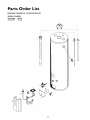
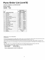
Parts Order List .........................................................................................................
30-31
5
Customer
Responsibilities
Thank You
for purchasing a Sears water heater.
Properly installed and maintained, it should give you years of
trouble free service. If you should decide that you want the new
water heater professionally installed by Sears call the local Sears
Service Center or any Sears store. They will arrange for prompt,
quality installation by Sears authorized contractors.
•
Abbreviations Found In This Instruction Manual
CSA - Canadian Standards Association
ANSI - American National Standards Institute
NFPA - National Fire Protection Association
AWARNING
This gas-fired water heater is design certified by CSA
INTERNATIONAL
under
American
National
Standard/CSA
Standard for Gas Water Heaters ANS
Z21.10.3 • CSA 4.3 (latest edition). The installation must
conform with this manual, Local Codes and with the latest
edition of the National Fuel Gas Code, ANSI Z223.1.
This publication is available from your local government or
public library,
gas company,
or by writing
NFPA,
Batterymarch Park, Quincy, MA 02269.
Ib ,
•
.
Read the "Safety Precauuons
section, pages 2 through 4 of
this manual first and then the entire manual carefully. If you
don't follow the safety rules, the water heater will not operate
properly.
It could cause DEATH,
SERIOUS
BODILY
INJURY AND/OR PROPERTY DAMAGE.
This manual contains instructions for the installation, operation, and maintenance
of the gas-fired water heater. It also
Product
MODEL NUMBER
•
contains warnings through out the manual that you must read
and be aware of. All warnings and all instructions are essential
to the proper operation of the water heater and your safety.
Since we cannot put everything on the first few pages, READ
THE ENTIRE
MANUAL BEFORE
ATTEMPTING
TO
INSTALL OR OPERATE THE WATER HEATER.
The installation
must conform with the instructions
in this
manual; gas company
rules; and Local Codes, or in the
absence of Local Codes, with the latest edition of the National
Fuel Gas code, ANSI Z223.1, also referred to as NFPA 54.
This publication
is available from your local government or
public
library
or gas company
or by writing
NFPA,
Batterymarch Park, Quincy, MA 02269.
If after reading this manualyou
have any questions or do not
understand
any portion of the instructions,
call the Sears
Service Center.
Carefully plan the place where you ate going to put the water
heater. Correct combustion, vent action, and vent pipe installation are very important in preventing death from possible
carbon monoxide poisoning and fires.
Examine the location to ensure the water heater complies
with the "Facts to Consider About the Location" section in
this manual.
For California installation this water heater must be braced,
anchored, or strapped to avoid falling or moving during an
earthquake.
See instructions
for correct installation
procedures. Instructions
may be obtained from your local dealer,
wholesaler, public utilities or California Office of the State
Architect, 400 P Street, Sacramento, CA 95814.
Massachusetts Code requires this water heater to be installed
in accordance
with Massachusetts
248-CMR
2.00: State
Plumbing Code and 248-CMR 5.00.
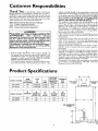
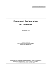
Specifications
TANK
CAPACITY
IN GALLONS
TYPE
OF
GAS
B.T.U.
RATE
RECOVERY
RATE GALS.
PER HOUR @
100°F RISE
MINIMUM
VENT
PIPE
153.337002
100
NATURAL
75,000
68.3
4"
153.337072
73
NATURAL
75,100
68.3
4"
MODEL NUMBER
153.337002
153.337072
(A)
(B)
(C)
(D)
(E)
DIAMETER
HEIGHT TO
JACKETTOP
LEG
HEIGHT
GASCONN.
HEIGHT
WATER
CONN.
26¾
24
68
58_
4
2
17_
15_
14"
8"
HOT OUTLET
I" N.ET.
GAS CONNECTION
I/2" N.P,T.
D
COLD INLET
I" N. P,T.
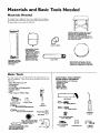
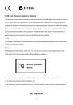
Materials
Materials
and Basic Tools Needed
Needed
To simplify the installation Sears has available the installation
parts shown below. You may or may not need all of these materials, depending on your type of installation.
WATER
HEATER
STAND
24"x24"x
18"
FOR USE WITH
WATER
HEATERS
INSTALLED
IN RESIDENTIAL
GARAGES
HAVING
A DIAMETER
24"
OR LESS AND
A RATED
CAPACITY
75
GALLONS
OR LESS
@
VENT
EXPANSION
TANKS
FOR THERMAL
EXPANSION
CONDITIIQFNS AVAILABLE IN
2 _-='ALLON AND 5
GALLON CAPACITY
THROUGH
LOCAL
SEARS STORE OR
SERVICE CENTERS
FLEXIBLE WATER
HEATER GAS CONNECTOR WITH
FITTINGS
VENT
ELBOW
PIPE
DRAIN
PANS AVAILABLE
IN 28"
DIAMETER
FOR WATER
HEATERS
HAVING
A DIAMETER
26" OR LESS
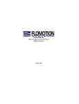
Basic Tools
ADDITIONAL
TOOLS NEEDED
WHEN SWEAT SOLDERING
• Tubing Cutters or Hacksaw
• Propane Torch
• Soft Solder
• Solder Flux
You may or may not need all of these tools, depending on your
type of installation. These tools can be purchased at your local
Scars store.
• Pipe Wrenches
(2) 14"
• Screwdriver
• Tin Snips
• 6 Foot Tape of Folding Rule
• Garden Hose
• Drill
• Pipe dope or Teflon Tape
_ EmeryCIoth
Wire Brushes
HACKSAW
GARDEN
HOSE
6 FOOT TAPE
1
SLOT-HEAD
3/4" WIRE BRUSH
PIPE
WRENCH
SCREWDRIVER
I12" WIRE BRUSH
PHILLIPS
SCREWDRIVER
PROPANE
TORCH
TIN SNIPS
ROLL OF LEAD FREE
SOFT SOLDER
ROLL OF TEFLON TAPE
(USE ONLY ON WATER
CONNECTIONS)
PIPE DOPE (SQUEEZE TUBE)
GUSH FOR WATER AND
AS CONNECTIONS)
DRILL
ROLL OF EMERY
CLOTH
7
SOLDER
FLUX
TUBING
CUTTER
Installation
Removing
OTurn
"OFF"
Instructions
the Old Water
Heater
the gas supply to the water heater.
Q
•,WARNING
]
If the main gas line shutoff serving all gas appliances is
used, also shut "OFF" the gas at each appliance. Leave all
gas appliances shut "OFF" until the water heater installat on s comp ete.
Disconnect
the vent pipe from the draft hood where
they connect to the water heater. In most installations
the vent pipe can be lifted off after any screw or other
attached devices are removed.
Dispose of the draft
hood. The new water heater has the draft hood which
must be used for proper operation.
[
®
®
Q
a. If you have copper piping to the water
heater, the two copper water pipes can
be cut with a hacksaw approximately
four inches away from where they connect to the water heater. This will avoid
cutting
off the pipes
too short.
Additional cuts can be made later if necessary. Disconnect
the temperature-pressure relief valve drain line. When the
water heater is drained, disconnect the
hose from the drain valve. Close the
drain valve. The water heater is now
completely disconnected
and ready to be
removed.
Q
b. If you have galvanized pipe to the water
heater, loosen the two galvanized pipes
with a pipe wrench at the union in each
line. Also disconnect the piping remaining to the water heater. These pieces
should be saved since they may be needed when reconnecting
the new water
heater. Disconnect the temperature-pressure relief valve drain line. When the
water heater is drained, disconnect the
hose from the drain valve. Close the
drain valve. The water heater is now
completely disconnected and ready to be
Q
the water to the water
QTurn
"OFF"
heater. Some installations
require that
the water be turned
off to the entire
house.
QCheck
a_,ain to make sure the gas supply
is OFF
to the water heater. Then disconnect the gas supply connection from
the gas control valve.
G
Attach
valve
drain
drain
faucet
water
a
hose to the water heater drain
and put the other end in a floor
or outdoors. Open the water heater
valve. Open a nearby hot water
which will relieve pressure in the
heater and speed draining.
_,WARNING
[
The water passingout of the drain valvemay be extremely I
hot. To avoid being scalded,make sure all connections are
tight and that the water flow is directed away from any
person.
,
renloved.
•
_CAUTION
Mineral buildupor sediment may have accumulated in the
old water heater. This causesthe water heater to be much
[ heavier than normal and this residue, if spilled out, could [
[ causestaining.
I
Installation
Instructions
(cont'd)
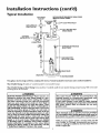
Typical Installation
HOT WATER
OUTLET
VACUUM RELIEF REQUIRED
(REFER TO LOCAL CODES)
BY SOME CODES
(
TO CHIMNEY
OR GAS
VENT
HOT
SPACE HEATER
SPACE HEATER
TEMPERED
WATER OUTLET
MIXING
VALVE
GAS
SUPPLY
--
TEMPERATURE-PRESSURE
RELIEF VALVE
--
DISCHARGE PIPE
(Do not cap or plug)
-DRAIN
DRAIN PAN
VALVE
I TO SUITABLE DRAIN
This appliance has been design certified as complying with American National Standards for water heaters and is considered suitable for:.
Water (Potable) Heating: All models are "considered suitable for water (potable) heating."
Water (Potable) Heating and Space Heating: Certain models are "considered suitable for water (potable) heating and space heating." Refer to the model
and rating plate of the water heater.
AWARNING
HOTTER
WATER
CAN SCALD:
Water heaters are
intended to produce hot water. Water heated to a temperature which will satisfy clothes washing, dish washing,
and other sanitizing needs can scald and permanently
injure you upon contact. Some people are more likely to
be permanently injured by hot water than others. These
include the elderly, children, the infirm, or physically/mentally handicapped. If anyone using hot water in your home
fits into one of these groups or if there is a local code or
state law requiring a certain temperature water at the hot
water tap, then you must take special precautions. In addition to using the lowest possible temperature setting that
satisfies your hot water needs, a means such as a mixing
valve, should be used at the hot water taps used by these
people or at the water heater. Mixing valves are available
at plumbing supply or hardware stores. Follow manufacturers instructions for installation of the valves. Before
changing the factory setting on the thermostat, read the
"Temperature
Regulation" section in this manual.
_WARNING
This water
heater shall not be connected
to any
heating
systems or component(s)
previously
used
with a non-potable
water heating appliance.
If this water
heater is also used for space heating
applications,
all piping and components
connected to
the water
heater
shall be suitable
for use with
potable water,
_,WARNING
Toxic chemicals such as used for treatment
of boilers
or non-potable water heating appliances shall never be
introduced into a potable water space heating system.
NOTE: To protect against untimely corrosion of hot and cold
water fittings, it is strongly recommended that di-electric
unions or couplings be installed on this water heater when connected to copper pipe.
Installation
Instructions
Facts to Consider
Location
About
(cont'd)
the
You should carefully choose an indoor location for the new
water heater, because the placement is a very important consideration for the safety of the occupants in the building and for
the most economical use of the appliance. This water heater is
not for use in mobile homes or outdoor installation.
• The location selection must provide adequate clearances for servicing and proper operation of the water heater.
AWARNING
Whether replacing an old water heater or putting the water
heater in a new location, the following critical points must be
observed.
This water heater must not be installed directly on carpeting.
Carpeting must be protected by a metal or wood panel
beneath the appliance extending beyond the full width and
depth of the appliance by at least 3 inches (76.2mm) in an)
direction, or if the appliance is installed in an alcove or closet
the entire floor must be covered by the panel. Failure to heec
this warning may result in a fire hazard.
• The location selected should be indoors as close as practical to
the gas vent or chimney to which the water heater vent is
going to be connected, and as centralized with the water piping system as possible. The water heater, as all water heaters,
will eventually leak. Do not install without adequate drainage
provisions where water flow will cause damage.
AWARNING
Minimum clearances between the water heater and combustible construction are I" at the sides and rear, 4" at the
front, and 6" from the vent pipe. Clearance from the top of the
jacket is 18" on most model_ Note that a lesser dimension may
be allowed on some models. Refer to the label on the water
heater adjacent to the gascontrol valve for all clearances.
ACAUTION
WATER HEATERS EVENTUALLY LEAK: Installation of the
water heater must be accomplished in such a manner that if
the tank or any connecti_'nsshould leak, the flow of water will
not cause damage to the structure. For this reason, it is not
advisable to install the water heater in an attic or upper floor
When such locations cannot be avoided, a suitable drain pan
shouldbe installed under the water heater. Drain pans are avail.
able at your local Sears store. Such a drain pan must be not
greater than 1¼ inchesdeep, havea minimum length and width
of at least 2 inches greater than the water heater dimensions
and must be piped to an adequate drain. The pan must not
restrict combustion air flow. Under no circumstances is the
manufacturer or Sears to be held liable for any water damage
in connection with this water heater.
AWARNING
A gaswater heater cannotoperate properlywithout the correct amount of air for combustion.Do not installin a confined
area sucha closet,unlessyou provideair asshownin the "Facts
to Cc_nsider
About the Location"section.Never obstructthe
flowof ventilationair If youhaveany doubtsor questionsat all,
callyour gascompany.Failureto providethe properamount of
combustionair canresult in a fire or explosionand cancause
DEATH, SERIOUSBODILYINJUly, OR PROPERTYDAMAGE.
AWARNING
INSTALLATIONS IN AREASWHERE FLAMMABLELIQUIDS
VAPORS) ARE LIKELY TO BE PRESENT OR STORED
GARAGES, STORAGE, AND UTILITY AREAS, ETC):
Flammableliquids(suchas gasoline,solvents,propane(LP) or
butane, etc.), all of which emit flammable vapors, may be
improperlystoredor usedin suchareas.The gaswater heater
pilot light or main burnercanignite suchvapors.The resulting
flashbackandfire cancausedeathor seriousburnsto anyonem
the area,aswellaspropertydamage.
If installationin suchareasisyour onlyoption,then the installation must be accomplishedin a way that the pilot flame and
mainburnerflameare elevatedfrom the floor at least 18inches.
While this may reduce the chancesofflammablevaporsfrom a
floor spillbeingignited,gasolineand otherflammablesubstances
shouldneverbe storedor usedin the same room or area containinga gaswater heateror other openflameor sparkproducingappliance.
NOTE: Flammablevaporsmay be drawnby air currentsfrom
i otherareasofthe structureto the appliance.
AWARNING
If this water heater willbe usedin beautyshops,barber shops,
cleaning establishments,or self-servicelaundrieswith dry
cleaningequipment,it is imperativethat the water heater or
water heatersbe installedso that combustionand ventilation
air be taken from outsidethese areas. Referto the "Facts to
ConsiderAbout the Location"sectionof this manual and also
the latesteditionofthe NationalFuelGasCode, ANSI Z223.1,
also referred to as NFPA 54 for specificsprovidedconcerning
air required.
AWARNING
Propellantsof aerosolspraysand volatile compounds,(cleaners, chlorinebasedchemicals,refrigerants,etc.) in addition to
beinghighlyflammablein manycases,will alsochangeto corrosive hydrochloricacid when exposedto the combustion
productsof the water heater.The results can be hazardous,
and also causeproductfailure.
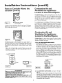
Figure I I
CLOSET INSTALLATION
(ACCEPTABLE)
A closet is any 4 sided enclosure which is less than 16' times the total
volume of all the gas fired appliances within the enclosure.
10
Installation
Instructions
Facts to Consider About the
Location (cont'd)
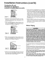
Combustion Air and
Ventilation for Appliances
Located in Unconfined Spaces
Unconfined
Space is a space whose volume is not less than 50
cubic feet per 1,000 Btu per hour of the aggregate input rating
of all appliances installed in that space. Rooms communicating
directly with the space in which the appliances are installed,
through openings not furnished with doors, are considered a
part of the unconfined space
®
Figure
In unconfined spaces in buildings, infiltration may be adequate
to provide air for combustion, ventilation and dilution of flue
gases. However, in buildings of tight construction (for example,
weather stripping, heavily insulated, caulked, vapor barrier, etc.),
additional air may need to be provided using the methods
described in Combustion Air and Ventilation for Appliances
Located in Confined Spaces, b.
ROOM INSTALLATION
(ACCEPTABLE)
2 ]
A room is any enclosure which is at least 16" times
greater than the total volume of all the gas fired appliances within the enclosure.
Combustion Air and
Ventilation for Appliances
Located in Confined Spaces
WATER
HEATER
Confined
Space is a space whose volume is less than 50 cubic
feet per 1,000 Btu per hour of the aggregate input rating of all
app]iances installed in that space.
ALCOVE INSTALLATION
(ACCEPTABLE)
I Figuro 3 I
(cont'd)
An alcove suitable for the installation of a water heater is a
restricted section of a room not separated from the room
by a door or partition and which meets the minimum
clearances for the specific model water heater listed
below.
ao
*When the ceiling height exceeds 8 feet, you are only
allowed to consicTer 8 _'eetwhen calculating the total volume of the enclosure.
12" MAX.
-
r_
t
ALL AIR FROM INSIDE BUILDINGS:
(See Figures l through 6)
The confined space shall be provided with two permanent
openings communicating
directly with an additional room(s)
of sufficient volume so that the combined
volume of all
spaces meets the criteria for an unconfined space. The total
input of all gas utilization equipment
installed in the combined space shall be considered in making this determination.
Each opening shall have a minimum free area of one square
inch per 1,000 BTU per hour of the total input rating of all
gas utilization equipment
in the confined space, but not less
than 100 square inches. One opening shall commence within
12 inches of the top and one commencing
within 12 inches
of the bottom of the enclosure.
VENTILATION
AIR
OPENINGS C
SVENT
DOOR
FRONT
VIEW
_
OF DOOR
3"MIN.
AIR DUCT
IFig-ro4]
[Flguro51
FURN
OPENINGS
I AI _Z] I WA
_._ER _
Figure 6 ]
AWARNING
b. ALL AIR FROM OUTDOORS:
(see Figures 7 through 9,
page 12)
The confined space shall be provided with two permanent
openings, one commencing within 12 inches of me top and
one commencing
within 12 inches from the bottom of the
enclosure. The openings shall communicate
directly, or by
ducts, with the outdoors or spaces (crawl or attic) that freely
communicate
with the outdoors.
Minimum
clearances between the water heater and
combustible construction are listed below:
Minimum
Side & Rear Clearances -- I"
Minimum front clearance from jacket to closet door _ 4"
Minimum
ceiling clearance from jacket top to combustible ceiling18".
It
Installation
Instructions
(cont'd)
Combustion Air and
Ventilation for Appliances
Located in Confined Spaces (cont'd)
Figure
7 ]
ALT I_LETAIR
5. Louvers and Grilles: In calculating free area, consideration
shall be given to the blocking effect of louvers, grilles or
screens protecting openings. Screens used shall not he smaller
than ¼ inch mesh. If the free area through a design of louver
or grille is known, it should be used in calculating the size
opening required to provide the free area specified. If the
design and free area is not known, it may be assumed that
wood louvers will be 20-25 percent free area and metal louvers
and grilles will have 60-75 percent free area. Louvers and
grilles shah be fixed in the open position or interlocked with
the equipment so that they are opened automatically during
equipment operation.
VENTILATIONLOOVERS
1. When directly communicating with the outdoors, each opening shall have a minimum free area of 1 square inch per 4,000
BTU per hour of total input rating of all equipment in the
enclosure. (See Figure 7.)
6. Special Conditions
Created by Mechanical
Exhausting or
Fireplaces: Operation
of exhaust fans, ventilation
systems
clomes dryers or fireplaces may create conditions requiring
special attention to avoid unsatisfactory operation of installed
gas utilization equipment.
2. When communicating with the outdoors through vertical
ducts, each opening shall have a minimum free area of 1
square inch per 4,000 _TU per hour of total input rating of
all equipment in the enclosure. (See Figure 8.)
_CHIMNEY
Water
OR GAS VENT
Piping
VENTILATION
LOUVERS
(each end c4 att_)
_WARNING
WATER
HOTTER WATER CAN SCALD: Water heaters are intended to
>reduce hot water. Water heated to a temperature which will
satisfy'clotheswashing, dishwashing, and other sanitizing needs
can scald and permanently injure you upon contact. Some peo)le are more likely to be permanently injured by hot water than
others. These include the elderly, children,the infirm, or pbysically/mentally handicapped. If anyone usinghot water in your home
fits into one of these groups or if there is a localcode or state law
requiring a certain temperature water at the hot water tap, then
_u must take special precautions. In addition to usingthe lowest
)ossibletemperature setting that satisfies your hot water needs,
a means suchas a mixing valve, shouldbe used at the hot water
taps used by these people or at the water heater. Mixing valves
are availableat plumbing supplyor hardware stores.Follow manufacturers instructions for installation of the valves, Before
changing the factory setting on the thermostat, read the
"Temperature Regulation" section in this manual.
HEATER
FURNACE
TLET
IN L'EI AIR OUCT
• a_ov e floor I
Figure
8 ]
I
I
I
3. When communicating with the outdoors through horizontal
ducts, each opening shall have a minimum free area of 1
square inch per 2,000 BTU per hour of total input rating of
all equipment in the enclosure. (See Figure 9.)
CHIMNEY
OR GAS VENT
This water heater shall not be connected to any heating systems
or component(s)
used with a non-potable
water heating
appliance.
_
--
Figure
9 ]
4. When ducts are
area as the flee
The minimum
shall not be less
:
.=...•-.-
-.-•-.-
lfa water heater is installed in a closed water supply system; such as
one having a back-flow preventer, check valve, water meter with a
check valve, etc.., in the cold water supply; means shall be provided
to control thermal expansion. Contact the local utility or local Sears
Service Center on how to control this situation.
OUTLet AIR DUCT
INLET Afft DUCT
]
NOTE: To _protect against untimely corrosion of hot and
cold water fittings, it is strongly recommended
that di-electric unions or couplings
be installed on this water heater
when connected to copper pipe.
used, they shall be of the same cross-sectional
area of the openings to which they connect.
short side dimension of rectangular air ducts
than 3 inches. (See Figure 9.)
NOTE: If using copper tubing, solder tubing to an adapter
before attaching the adaptor to the cold water inlet connection,
Do not solder the cold water supply line dlrecdy to the cold
water inlet. It will harm the dip tube and damage the tank.
12
Installation
Instructions
Temperature-Pressure
(cont'd)
Relief Valve
AWARNING
A WARNING
At the time of manufacture this water heater was provided
with a combination temperature-pressures
relief valve certified by a nationally recognized testing laboratory that main.
tains periodic inspection of production of listed equipment or
materials, as meeting the requirements for Relief Valves and
Automatic
Gas Shutoff Devices for Hot Water Supply
Systems, and the latest edition of ANSI Z21.22 and the code
requirements of ASME. If replaced, the valve must meet the
requirements of local codes, but not lessthan a combination
temperature and pressure relief valve certified as meeting
the requirements
for Relief Valves and Automatic Gas
Shutoff Devices for Hot Water Supply Systems, ANSI Z21.22
by a nationally recognized testing laboratory that maintains
periodic inspection of production of listed equipment or
materials.
The valve must be marked with a maximum set pressure not
to exceed the marked hydrostatic working pressure of the
water heater 050 Ibs./sq. in.) and a discharge capacity not
less than the water heater input rate as shown on the model
rating plate. (Electric heaters_, watts divided by I000 x 3415
equal BTU/Hr. rate.)
Your local jurisdictional authority, while mandating the use of
a temperature-pressure
relief valve complying with ANSI
Z21.22 and ASME, may require a valve model different from
the one furnished with the water heater.
Compliance with such local requirements
must be satisfied
by the installer or end user of the water heater with a locally
prescribed temperature-pressure relief valve installed in the
designated opening in the water heater in place of the factory furnished valve.
For safe operation of the water heater, the relief valve must
not be removed from it's designated opening or plugged.
The temperature-pressure
relief valve must be installed
directly into the fitting of the water heater designated for the
relief valve. Position the valve downward and provide tubing
so that any discharge will exit only within 6 inches above, or
at any distance below the structural floor. Be certain that no
contact is made with any live electrical part. The discharge
opening must not be blocked or reduced in size under any
circumstances. Excessive length, over 15 feet, or use of more
than two elbows can cause restriction
and reduce the discharge capacity of the valve.
_o valve or other obstruction is to be placed between the
relief valve and the tank. Do not connect tubing directly to
discharge drain unless a 6" air gap is provided. To prevent
bodily injury, hazard to life, or property damage, the relief
valve must be allowed to discharge water in quantities should
circumstances demand. If the discharge pipe is not connected to a drain or other suitable means, the water flow may
cause property damage.
The Discharge Pipe:
Must not be smaller in size than the outlet pipe size of the
valve, or have any reducing couplings or other restrictions.
Must not be plugged or blocked.
Must be of material listed for hot water distribution.
Must be installed so as to allow complete drainage of both
the temperature-pressure relief valve, and the discharge
pipe.
Must terminate at an adequate drain.
Must not have any valve between the relief valve and tank.
The temperature-pressure
relief valve must be manually
operated at least once a year. Caution should be taken to
ensure that (I) no one is in front of or around the outlet of
the temperature-pressure relief valve discharge line, and (2)
the water manually discharged will not cause any bodily
injury
or property damage because the water may be
extremely hot.
If after manually operating the valve, it fails to completely
reset and continues to release water, immediately close the
cold water inlet to the water heater, follow the draining
instructions, and replace the temperature-pressure
relief
valve with a new one.
A WARNING
If a water heater is installed in conjunction with a separate storage vessel, the storage vessel must also be
equipped
with a temperature-pressure
relief valve
complying with the Standard for Relief Valves and Hot
Water
Supply Systems,
ANSI Z21.22.
The hourly
rated temperature
steam BTU discharge capacity of
the temperature-pressure
relief valve(s) shall not be
less than the combined
BTU input of the water
heater(s) supplying water to the storage vessel(s).
COLD
HOT
SHUTOFF
VALVE
PRESSURE
RELIEF VALVE
DISCHARGE PIPE
(Do not cap or plug)
RELIEF VALVEOPENING
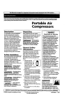
At the time of manufacture, this water heater was provided with a combinationtemperature-pressure relief valve listed as complying with the standard for relief valves
and automatic gas shut-off devices for hot water supply systems,ANSI Z21,22. For
safeoperarJon of the water heater, the relief valvemust not be removed from its designatedpoint of installationor plugged.
Your local jurisdictional authorit7. while mandatingthe use of a temperauJre-pressure
relief valve complyingwith ANSI Z21.22 and ASHE, may require a valve model different from the one furnished with the water heater
Compliance with such local requirements must be satisfiedby the installer or end user
of the water heater with a Locagy prescribed temperature-pressure
relief valve
installedin the designatedopening in the water heater
See manual heading-"Temperature-Pressure Relief Valves"for installationand maintenance of relief valve,dischargeline, and other sefeL
7 precautions.
13
Installation
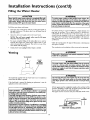
Filling the Water
Instructions
(cont'd)
Heater
AWARNING
A CAUTION
Never use this water heater unless it is completely filled with
water. To prevent damage to the tank, the tank must be filled
with water. Water must flow from the hot water faucet
before turn ng ON
To insure proper venting of this gas-fired water heater, the I
correct vent pipe diameter must be utilized. Any additions or
deletions of other gas appliances on a common vent with this
water heater may adversely affect the operation of the water
heater. Consult the local Sears Service Center or gas utility if
any such changes are planned.
gas to the water heater.
To fill the water heater with water:
Close the water heater drain valve by turning the handle to
the right (clockwise). The drain valve is on the lower front of
the water heater.
For proper venting in certain installations, a larger diameter vent
pipe may be necessary. Due to great variances in installations,
unforeseeable by the manufacturer of the water heater, you must
consult your gas company to aid you in determining the proper
venting for your water heater from the vent tables in tl_e latest edition of the National Fuel Gas Code ANSI Z223.1, also referred to
as NFPA 54.
Open the cold water supply valve to the water heater.
NOTE: The cold water supply valve must be left open
when the water heater is in use.
To insure complete filling of the tank, allow air to exit by
opening the nearest hot water faucet. Allow water to run
until a constant flow is obtained. This will let air out of the
water heater and the piping.
Check the venting system for signs of obstruction
and replace if needed.
Check all new water piping for leaks. Repair as needed.
The combustion
and ventilation
or deterioration
air flow must not be obstructed.
AWARNING
Venting
Obstructed or deteriorated vent systems may present a serious
health risk or asphyxiation.
TO CHIMNEY
PLACE
IN
LEGS
HOLES
-
AWARNING
]
The-water heater wit_stalled
must be properly I
vented to a chimney which terminates outdoors. Never oper- I
ate the water heater unlessit isvented to the outdoors and has I
adequate air supply to avoid Hsks of improper operation, explo- [
slon or asphyxiation.
EIDED
!
AWARNING
]
The draft hood supplied with this water heater must be installed as "
shown before the heater is operated.
The vent pipe from thrust
be no less than the I
diameter of the draft hood outlet on the water heater, and I
must slope upward to the chimney at least ¼ inch per linear I
If the draft hood is removed for cleaning or replacement it must be
replaced in reverseorder as removed.
foot
]
All vent gases must be completely vented to the outdoors of the
structure
(dwelling). Installonly
the draft hood provided with
the new water heater and no other draft hood.
Vent pipes must be secured at each joint with sheet metal screws.
AWARNING
VENT DAMPERS - Any vent damper, whether it is operated
thermally or otherwise must be removed if its use inhibits proper drafting of the water heater.
Thermally Operated Vent Dampers: Gas-fired water heaters
having thermal efficiency in excess of 80% may produce a relatively low flue gas temperature. Such temperatures may not be
high enough to properly open thermally operated vent
dampers. This would cause spillage of flue gases and may cause
carbon monoxide poisoning.
Vent dampers must bear evidence of certification as complying
with the latest edition of American National Standard ANSI
Z21.68 (ANSI Z21.66 & 67, respect_ely, cover electrically and
mechanically actuated vent dampers). Before installation of any
vent damper, consult your local Sears Service Center or the gas
utility for further information.
I
I
I
VENT
14
PIPE INSTALLATION
q
Installation
Venting
Instructions
(cont'd)
(cont'd)
There must be a minimum of 6" clearance between single wall
vent pipe and any combustible material Fill and seal any clearance between single wall vent pipe and combustible
material
with mortar mix, cement, or other noncombustible
substance.
For other than single wall, follow vent pipe manufacturer's clearance specifications.
To insure a tight fit of the vent pipe in a
brick chimney,
seal around the vent pipe with mortar
mix
cement.
_WARNING
Minimum clearances between the water heater and combustible construction are I" at the sides and rear, 4" at the
front, and 6" from the vent pipe. Clearance from the top of the
jacket is 18" on most models. Note that a lesserdimension may
be allowed on some models. Refer to the label on the water
heater adjacent to the gas control valve for all clearances.
_,WARNING
_, WARNING
Failureto haverequired clearancesbetween vent pipingand
combustiblematerial will result in a fire hazard.
A gas water heater cannot operate properly without the correct amount of air for combustion. Do not install in a confined
area sucha closet, unlessyou provide air as shownin the "Facts
to Consider About the Location" section. Never obstruct the
flow of ventilatlon air. If you have any doubts or questionsat all,
call your gas company. Failure to provide the proper amount of
combustion air can result in a fire or explosion and can cause
DEATH, SERIOUS BODILY INJUR_, OR PROPERTY DAMAGE.
Where an exhaust fan is installed in the same room as the
water heater, air will be drawn into the room through the
chimney. Air supply openings must be large enough to admit
air exhausted by the fan and that requiredby
all gas burning
appliances. A down÷draft or back-draft will prevent proper
combustion, causing soot wh_h may result in serious damage
to the water heater.
•,WARNING
Where continuous or intermittent backdraft is found to exist,
check chimney conditions. In some cases a blower type flue
gas exhauster must be employed between the appliance and
t_e stack to assure proper venting and correct combustion.
I
Be sure vent pipe is properly connected to prevent escape of I
dangerous flue gaseswhich could cause deadly asphyxiation. I
Combining vents as shown below is satisfactory, providing the
basic rules of good venting are observed. In eiti_er case, the
vertical rise above draft hood (X) before any fittings, should be
as great as possible. All venting connections should be made
in accordance with local codes and ordinances.
_,WARNING
Chemical vapor corrosion of the flue and vent system may
occur if air for combustion contains certain chemical vapors.
Spray can propellants, cleaning solvents, refrigerator and air
conditioner refrigerants, swimming pool chemicals, calcium
and sodium chloride, waxes, bleach, and process chemicals are
typical compounds Which are potentially corrosive.
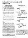
Gas Piping
_,WARNING
Make sure the gas supplied is the same type listed on the
model rating plate. The inlet gas pressure must not exceed
10.5 inches water column (2.6kPa) for Natural Gas and 13
inches water column (3.5kPa) for Propane (L.R) Gas. The
minimum inlet gas pressure listed on the model rating plate
is for the purpose of input adjustment.
When vents are combined, area of the combined vent
should be equal to area of the largest single vent, plus 50%
of area of all others joining it.
EXAMPLE To combine two 6 vents with an 8' vent, the
area of a combined vent should be one half
area of two 6" vents (14+14) plus area of 8"
vent (50) = 78 .sq.inches. Referring to chart, 78
sq. inches requires a 10" diameter vent.
VENT
SIZE
SQUARE
INCHES
VENT
SIZE
SQUARE
INCHES
5"
20
28
38
50
64
10"
12"
14"
16"
18"
79
113
154
201
254
6"
7"
8"
9"
•,WARNING
, I
If the gas control valve is subjected to pressures exceeding ½ [
pound per square inch (3.SkPa), the damage to the gas con- I
tro valve cou d resu t in a fire or explosion from leaking gas. I
AWARNING
If the main gas line shutoff serving all gas appliances is used,
also turn "OFF" the gas at each appliance. Leave all gas appliances shut off until the water heater installation is complete.
15
Installation
Instructions
(cont'd)
Gas Piping (cont'd)
CORRECT
WATER
TOTAL
GAS
PIPE
SIZE
HEATERS
OPERATING
ON NATURAL
Basedon Inlet Gas Pressuresof 0.5 psigor Lessand
a Pressure Drop of 0.3 inchesWater Column.
(Basedon a 0.60 SpecificGravity Gas)
INPUT*
DISTANCE
TO METER,
GAS
IN FEET
BTU/HR
20
30
60
90
125 150 200
75,000
150,000
'/2
3/,
3/,
3/4
3/,
3/4
3/,
3/4
t
3/,
I
I
I
I
17,
*Of all gas appliances
l line.
100,000
GAS PIPING
WITH
FLEXIBLE
CONNECTOR
FOR
I
I
17,
MANUAL
I
I
17,
A gas line of sufficient size must be run to the water heater.
Consult the latest edition of National Fuel Gas Code ANSI
Z223.1, also referred to as NFPA 54 and the gas company conceming pipe size.
_GAS
SUPPLY PIPING
SHUTOFF
VALVE
FLEXIBLE
GAS CONNECTOR
LABELED
AS COMPLYING
WITH
ANSI STANDARDS
UNION
(Optional)
GROUNDJOIN
GAS
CONTROL
VALVE
____
There must be:
• A readily accessible manu_i shut off valve in the gas supply line
(Sediment
trap)
DRIP LEG
3"_IN._
I CAP
serving the water heater, and
• A drip leg (sediment trap) ahead of the gas control valve to help
prevent dirt and foreign materials from entering the gas control
valve.
GAS
• A flexible gas connector or a ground oint union between the
shutoff valve and control valve to permit servicing of the unit.
Be sure to check all the gas piping for leaks before lighting the
water heater. Use a soapy water solution, not a match or open
flame. Rinse offsoapy solution and wipe dry.
PIPING
PIPE
"
WITH
ALL BLACK
TO GAS CONTROL
_
IRON
GAS SUPPLYPIPING
I1
MANUAL _:_
Standard Models are for installation up to 3,300 feet above sea
level.
High Altitude Models are for installation from 3,300 to 5,500 feet
above sea level.
Ifa standard model is installed above 3,300 feet or a high altitude
models is installed above 5,500 feet, the input rating must be
reduced at the rate of 4 percent for each 1,000 feet above sea level.
Contact your local Sears Service Center or gas utility for further
information.
SHUTOFF
_l[_
VALVE
_'_
GROUND
I
BLACK PIPE
GAS
CONTROL
VALVE
AWARNING
The appliance and it_
must be leak tested
beforeplacingthe appliance in operation.
JOINT
U__
3" MIN.
_J CAP
AWARNING
• The appliance and its individual shutoff valve must be disconnected from the gas supply piping system during any pressure
testing of the gas system at test pressures in excess of
pound per square inch (3,5kPa).
• The appliance must be isolated from the gas supply piping system by closing its individual manual shutoff valve during any
pressure testing of the gas supply piping system at test pressurfs equal or lessthan I'/2pound per square inch (3.5kPa),
AWARNING
Contaminantsin the gaslinesmay causeimproper operation
of the gascontrol valvethat may result in fire or explosion.
Beforeattachingthe gaslinebe surethat all gaspipe isclean
on the inside.To trap anydirt or foreignmaterial in the gas
supply line, a drip leg (sometimes called a sediment trap)
must be incorporated in the piping. The drip leg must be
readily accessible.Installin accordancewith the "Gas Piping"
section. Refer to the latest edition of the National Fuel Gas
Code, ANSI Z223.1, also referred to as NFPA 54.
I
AWARNING
Use pipe joint compound or teflon tape marked as being
resistantto the actionof petroleum [Propane (I-E)] gases.
16
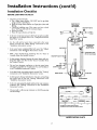
Installation
Instructions
Installation
Checklist
BEFORE LIGHTING
THE PILOT:
(cont'd)
Check the gas lines for leaks.
a, Use a soapy water solution. DO NOT test for gas leaks
usinga match or open flame•
b. Brush the soapy water solution on all gas pipes, joints and
fittings•
c. Check for bubbling soap. This means you have a leak.
Turn "OFF" gas andmake the necessary repairs.
d. Recheck for leaks.
e. Rinse off soapy solution and wipe dry.
VENT PIPE TO
OUTDOORS
OR
CHIMNEY
SHUTOFF
HOT
COLD
• ls the new temperature-pressure relief valve properly installed
and piped to an adequate drain? See "Temperature-Pressure
Relief Valve" section•
UNION
• Are the cold and hot water lines connected to the water
heater correctly? See "Water Piping" instructions in the
"Installation Instructions" section.
DRAFT
HOOD
TEHPERATUREPRESSURE
RELIEF VALVE
/
GAS
• Is the water heater completely filled with water? See "Filling"
instructions in the "Installation Instructions" section•
SUPPLY
--
• Will a water leak damage anything?
Consider About the Location" section.
VALVE
DISCHARGE
PIPE
(Do not cap or plug)
See the "Facts to
SHUTOFF
VALVE
• Is there proper clearance between the water heater and anything that might catch fire. See the Facts to Consider About
the Location" section.
[]
TEE -_J
• Do you have adequate ventilation so that the water heater
•
....
wdl
operate properly._ See *cCombustion
Air and Ventdatlon .
in the "Installation Instructions" section,
•
•
DRIP LEG -----_
(Sediment trap)
CAP
Is the draft hood vent piping properly secured? See "Venting"
instructions in the "Installation Instructions" section.
DRAIN
6" AIR
VALVE
Is there proper clearance between the vent pipe and anything
that might catch on fire? See "Venting" instructions
in the
"Installation Instructions" section•
FLOOR
DRAIN
• Is the vent pipe properly sloped and does the vent terminate
outdoors? See "Venting" instructions in the "Installation
Instructions" section.
SUITABLE FOR WATER (POTABLE)
HEATING ONLY
•
Do you need to call your gas company
and its hookup?
to check the gas pipe
B_
UAXI_
QALS.n
HyO_TA_
150
psi
AUTOMATIC
AUTOMATIC
GAS pnESSU_
I
I
wc
I
wc
STORAGE WATER HEATER
CIRCULATING
TANK WATER HEATER
MODEL RATING
17
_ WC
PLATE
w¢
GAP
Operating
Instructions
Lighting
_,WARNING
BEFORE LIGHTING
[PROPANE
(L.P.) GAS WATER
HEATERS]: Propane (L.P.) gas is heavier than air. Should there
be a leak in the system, the gas will settle near the ground.
Basements, crawl spaces, skirted areas under mobile homes
(even when ventilated), closets and areas below ground level will
serve as pockets for the accumulation of this gas. Before
attempting to light or relight the water heater's pilot or turning
on a nearby electrical light switch, be absolutely sure there is no
accumulated gas in the area. Search for odor of gasby sniffingat
ground level in the vicinity of the appliance. If odor is detected,
follow steps indicated at "For Your Safety" on the cover page of
thismanual then leave the premises.
Figure
I0 ]
Figure
II]
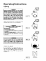
Lighting and operating instructions are located on front of the
wat:r heater, above or to one side of the gas control valve.
_,WARNING
AN ODORANT IS ADDED TO THE GAS USED
BY THIS WATER HEATER.
FOR YOUR SAFETY
IF YOU SMELL GAS:
Do not try to light any appliance.
Do not touch any electrical switch; do not use any phone in
your building.
Immediately call your gas supplier from a neighbor's phone.
Follow the gas supplier_ instructions.
If you cannot reach your gas supplier, call the fire
department.
_,WARNING
DO NOT force the gas control knob. Use only your hand to
push it down to light the pilot, or to turn it to "ON", "OFF"
or "PILOT". Never use a tool such as a lev_, wrench or plier_ Do not hit or damage the knob. A damaged knob may
result in an explosion and serious injury. If you have problem
turning the knob, call the gas supplier immediately.
CHECK
FOR
Figure 12]
LEAKS
Be sure to check all your gas pipes for leaks before lighting your
water heater. Use a soapy water solution, not a match or open
flame. Check the fac,!ory gas,fittings after pilot is lit and gas control knob is still in PILOT pos!tion;, Then, check the fittings
when the main burner is turned
ON . Use a soapy water solution for this, too.
INNER
i
I
I
I Figure 13 ]
18
OUTER
DOOR
Operating
Instructions
Lighting
label
on the water
FOR YOUR
heater
SAFETY
(cont'd)
as it appears
READ
above
the thermostat
BEFORE
If you do not follow these instructions exactly, a fire or explosion
l may result causing propertyWARNING
damage, personal injury or loss of life.
A. This appliancehas a pilot which must be lighted by
hand.Whenlightingthe pilot,follow theseinstructions
exactly.
3.BEFORELIGHTINGsmellall aroundthe appliancearea
for gas. Re sure to smell next to the floor because
somegasis heavierthan air andwill settleon thefloor.
WHATTODOIF YOUSMELLGAS
• Do not try to lightanyappliance.
• Do not touch any electric switch; do not use any
phonein yourbuilding.
• Immediatelycall yourgas supplierfroma neighbor's
phone.Followthegassupplier'sinstructions.
LIGHTING
• If you cannotreach your gas supplier,call the fire
department.
C. Use onlyyour handto pushin or turn the gas control
knob.Never usetools. If the knobwill not pushin or
turnby hand,don'ttry to repairit, call a qualifiedservicetechnician.Forceor attemptedrepairmay result
in a fire or explosion.
D. Do not use this applianceif any part has been under
water.Immediatelycall a qualified servicetechnician
to inspecttheapplianceand to replaceanypartof the
controlsystem and any gas controlwhichhas been
underwater.
INSTRUCTIONS
9. Push in control knob all the way and hold down.
Immediately light the pilot with a match. Continue
to hold control knob in for about one (f) minute
after the pilot is lit. Release knob and it will pop
back up. Pilot should remain lit. If it goes out,
repeat steps 3 through8.
• If knobdoes not pop up whenreleased,stop and
immediatelycall your service technician or gas
supplier.
• If the pilot will not stay lit after several tries
depressand turnthe gas controlknobclockwise
1. STOP!Readthe safetyinformationaboveon this label.
2. RemoveouterdSor.
3. Set the thermostat to lowest setting by turning the
watertemperaturedial clockwise,(_)
to its lowest
temperaturesetting(with arrowon dial)as shown.DO
NOT FORCE.
_,.Turngas controlknobclockwiseV 1 to "OFF" posi@)
to "OFF" and call yourservicetechnician
tion. Knob cannot be turned from "PILOT" to "OFF"
or
gassupplier.
(Figure10,page18)
unlessknob is depressedslightly.DO NOT FORCE,
10. Replace(or close) inner door.Replaceouter door if
(Figure10,page18)
door does not,covergas controlon/offknob or tem5. Wait five (5) minutesto clear out any gas. If you then
peratureadjustmentknob.(Figure13,page18)
smell gas, STOP!Follow"R" in the safetyinformation
11.
Atarms lengthaway,turn gascontrolknobcounterabove on this label. If you don't smell gas, go to the
nextstep.
clockwise _
to the full "ON" position.
6. Remove (or open) inner door located below the gas
WARNING Do not use gas control knob to reg.
controlunit.(Figure13, page18)
n _.
ulate gas flow. (Figure12, page18)
7.Find pilot-followmetal
THEBMOCOUPLE[_ PILOT
BURNER 12. At arms length away,set the thermostatto desired
tube fromgascontrol.
11_/
setting. The mark ( • ) indicative of approximate
The pilotis locatedin
_]_J
120°F is preferred starting point. Some local laws
frontof the burner.
IL_-I'_
may requirea lowerstartingpoint.If hotter wateris
8.If youdon'tsmellgas,turnknobongascontrolcounter
desired,see instructionmanualand "warning" below.
13.Replacetheouterdoorif notreplacedin step10.
clockwise_,
to "PILOT"position.(Figure11,page18)
WARNING
Hotter water increases the risk of scald injury.Before changing temperaturesetting see instructionmanual.
For operationat outlet water temperature not in excess of 180°F.
TO TURN
OFF GAS TO APPLIANCE
1. Set the thermostat to lowest setting by turning the
watertemperaturedial clockwise(F_,)
to its lowest
temperaturesetting(with arrowon dial)as shown.DO
NOT FORCE.
2. Turngascontrolknobclockwise_,)
to "OFF" position. Knob cannotbe turnedfrom "PILOT" to "OFF"
unlessknobis depressedslightly.DO NOT FORCE.
(Figure10,page 18)
3. Replaceouterdoor(if removed).
]9
Operating
Temperature
Instructions
(cont'd)
Regulation
Due to the nature of the typical gas water beater, the water temFoerature in certain situations
may vary up to 30°F higher or
wer at the point of use such as, bathtubs, showers, sink, etc.
Turn the water temperature dial clockwi_{_"'_)
to decrease
the temperature,
or counterclockwise
(_€" "_) to increase the
temperature.
This means that when the temperature adjustment dial is set at
the mark approximating
120 ° F, the actual water temperature at
any hot water tap could be as high as 150°F or as low as 90°E
Any water heater's intended purpose is to heat water. Hot water
is needed for cleaning (bodies, dishes, clothing). Hot water will
present a scald hazard. Depending on the time element, and the
people involved (normal
adults, children,
toddlers,
elderly,
infirm, etc.) scalding may occur at different temperatures.
AWARNING
HOTI'ER WATERCAN SCALD:Water heatersare intendedto
_roducehot water Water heatedto a temperature whichwill
satisfyclotheswashing,dishw_sfiing,and other sanitizingneeds
canscaldand permanentlyinjureyouupon contact.Somepeo.
de are more likelyto be permanentlyinjuredbyhot waterthan
others.Theseincludethe elderly,children,the infirm,or physically/mentally handicapped.
If anyoneusinghot water in your home
fitsintoone ofthesegroupsor ifthere isa localcodeor statelaw
requiringa certaintemperaturewater at the hot watertap,then
_u musttake specialprecautions.
In additionto usingthe lowest
_ossibletemperaturesettingthat satisfies
your hot water needs,
t meanssuchasa mixingvalve,shouldbe usedat the hot water
tapsusedby these peopleor at the water heater.Mixingvalves
are availableat plumbingsupplyor hardwarestores.Followman.
ufacturers instructionsfor installationof the valves.Before
changing the factory setting on the thermostat, read the
"Temperature Regulation"sectionin thismanual.
t
•
Is a thermostat
setting of approximately
120°E
which will supply hot water at the most economical temperatures.
A Is a thermostat
setting of approximately
130°E
B-Is a thermostat
setting of approximately
140°E
C-Is
a thermostat
setting of approximately
150°E
D-Is a thermostat
setting of approximately
160°E
VERY HOT-Is
AWARNING
I
Never allowsmallchildrento usea hot water tap, or to draw I
their own bath water. Never leavea childor handicappedpersonunattended n a bathtubor shower.
a thermostat setting of 180°E It is recommended that the dial be set lower whenever possible.
NOTE: Water temperature range of 120°-140°F recommended by most dishwasher manufacturers.
The thermostat
of this water heater has been factory set at its
lowest position, to reduce the risk of scald injury. It is adjustable
and must be reset to the desired temperature setting. The mark
(•) indicative of approximately
120°F is the preferred starting
point. Some states have a requirement for a lower setting, lfyou
need hotter water, follow directions for temperature adjustment,
but beware of the warnings in this section.
AWARNING
Should overheating occur or the gas supply fail to shut off,
I tum "OFF" the manual gas control valve to the appliance.
2O
Service
and Adjustment
Tank (Sediment)
Burner
Cleaning
Sediment
build-up
on the tank bottom
may create varying
amounts of noise, and if left in the tank will cause premature
tank failure. In some water areas, you may not be able to drain
all sediment deposits by simply draining the tank. In these cases
Mag Erad (part no. 23600) can be used to help remove the sediment deposits. This may be ordered from the Sears Service
Center. For ordering, refer to the "Parts Order List" section.
Venting System
Inspection
A,WARNING
]
Do not use this appliance if any part of it has been under water.|
Immediately call a Sears Service Technician to inspect thel
appliance and to replace the gas control or any part of the/
burner system which has been under water.
[
At least once a year a visual inspection should be made of the
main burner and pilot burner. The drawing is for your reference.
Inspection
You should check for sooting
impair proper combustion.
At least once a year a visual inspection should be made of the
venting system. You should look for:
• Obstructions
which could cause improper venting. The combustion and ventilation air flow must not be obstructed.
Damage or deterioration
which could cause improper venting
or leakage of combustion products.
Rusted flakes around top of water heater.
which
is not normal
and will
_,WARNING
Chemical vapor corrosior_of the flue and vent system may
occur if air for combustion contains certain chemical vapors.
Spray can propellants, cleaning solvents, refrigerator and air
conditioner refrigerants, swimming pool chemicals, calcium
and sodium chloride, waxes, bleach, and process chemicals are
typical compounds which are potentially corrosive.
•,WARNING
_,WARNING
J
Soot build-up indicates a problem that requires correction I
before further use. Turn "OFF" gas to water heater and leave J
"OFF" until repairs are made, because failure to correct the |
cause of the sooting can result in a fire or explosion causingJ
DEATH, SERIOUS BODILY INJUR_, OR PROPERTY DAMAGE. J
J
Obstructed or deteriorated vent systems may present a serious
health risk or asphyx at on.
A, WARNING
Burner
In the event
instructions:
J
Be sure the vent piping is properly connected to prevent
escape of dangerous flue gasses which could cause deadly
Cleaning
your
burner
needs
cleaning,
use the following
If inspection of the burner shows that cleaning is required, turn
the gas control knob clockwise (f'_)
to the "OFF" position,
depressing slightly.
asphyxiation.
NOTE: The knob cannot be turned from "PILOT" to "OFF"
unless knob is depressed sllghdy. DO NOT FORCE.
AWARNING
I
Loose deposits on or around the burner can be removed by carefully using the hose of a vacuum cleaner inserted through the
access door of the water heater. If the burner needs to be removed
for additional cleaning, call the Sears Service Center to remove
and clean the burner and correct the problem that required the
burner to be cleaned.
If after inspection of the vent system you found sooting or
deterioration, something is wrong. Call the local gas utility to I
correct the problem and clean or replace the flue and venting
before resum ng operation of the water heater.
21
Service
and Adjustment
(cont'd)
Draining
The water heater should be drained if being shut down during
freezing temperatures.
Also periodic draining and cleaning of
sediment from the tank may be necessary.
AWARNING
When checkingthe temperature-pressurerelief valveoperation, make sure that (I) no one is in front of or around the
outlet of the temperature-pressurerelief valvedischargeline,
and (2) that the water manuallydischargedwill not causeany
property damagebecausethe water may be extremely hot.
If after manually operating the valve, it fails to completely
reset and continuesto release water, immediately closethe
cold water inlet to the water heater, follow the draining
instructions, and replace the temperature-pressure relief
valvewith a new one.
Turn the gas control knob to the "OFF" position.
CLOSE the cold water inlet valve to the water heater.
OPEN a nearby hot water faucet and leave open to allow for
draining.
Connect a hose to the drain valve and terminate to an adequate drain.
OPEN the water heater drain valve to allow for tank
draining.
NOTE: If the water heater is going to be shut down and
drained for an extended period, the drain valve should be
left open with hose connected allowing water to terminate
to an adequate drain.
Close the drain valve.
Follow instructions
in the "Filling The Water Heater"
section.
Follow the lighting instructions in the "Lighting" section to
restart the water heater.
Temperature-Pressure
Valve Operation
Housekeeping
Vacuum around base of water heater for dust, dirt, and lint on a
regular basis.
Combustible materials such as clothing, cleaning materials, or
flammable liquids, etc. must not be placed against or adjacent to
the water heater.
To insure sufficient ventilation and combustion air supply, proper clearances from the water heater must be maintained at all
times.
Relief
Service
The temperature-pressure relief valve must be manually operated
at [east once a year.
Before calling for repair service, read the Start Up Conditions
and Operational
Conditions
found in the Troubleshooting
Guide of this manual.
If a condition persists or you are uncertain about the operation
TEMPERATURE-PRESSURE
of the water heater, let a qualified
person check it out.
Contact SEARS Repair Services
(1-800-469-4663).
DISCHARGE
PIPE
Failure to install and maintain a new properly listed temperature-pressure relief valve will release the manufacturer from any
claim which might result from excessive temperature or pressure.
AWARNING
If the temperature-pressure
relief valve on the appliance
weeps or discharges periodically, this may be due to thermal
expansion. Your water heater may have a check valve
installed in the water line or a water meter with a check
valve. Consult the Sears Service Center for further information. Do not plug the temperature-pressure relief valve.
22
at 1-800-4-MY-HOME
Troubleshooting
Guide
Start Up Conditions
THERMAL
EXPANSION
HOT
COLD
Water supply systems may, because of high line pressure, frequent cut-offs, the effects of water hammer and others, have
installed devices such as pressure reducing valves, check valves,
back flow preventers,
etc. to control these types of problems.
When these devices are not equipped with an internal by-pass,
and no other measures are taken, the devices cause the water system to be closed. As water is heated, it expands (thermal expansion) and closed systems do not allow for the expansion of heated water.
WATERHEATER
COLDWATER
INLETFITTING
(3)
PRESSURE
REDUCING
VALVEWITH
By.PASS
EXPANSION
TANK
(0
1
(z)
PRESSURE GAUGE
WATER
SHUTOFF
The water within the water heater tank expands as it is heated
and increases the pressure of the water system. If the relieving
point of the water heater's temperature-pressure
relief valve is
reached, the valve will relieve the excess pressure. The temperature-pressure
relief valve is not intended
for the constant
relief of thermal expansion.
This is an unacceptable condition
and must be corrected.
RECOMMENDED INSTALLATION
(VERTICAL MOUNTING)
It is recommended
that any devices installed which could create
a closed system have a by-pass and/or the system have an expansion tank to relieve the pr_sure built by thermal expansion in
the water system. Expansion
tanks are available for ordering
through the Sears Service Center. Contact the local plumbing
inspector, water supplier, and/or the Sears Service Center for
assistance in controlling these situations.
Thermal
Model
Number
Expansion
Ex
-
pans on
Tank
Capacity
Needed
HOT
STRAPPING
(3)
Dimensions in Inches .! Pipe Fitting
Dia_meter 1 Length ] On Tank
5
Expansion
(0
]
[
_73
/4_psi
PRESSURE
GAUGE
Water Heater Capacity
5
*Highest recorded inlet water
regulated water pressure.
I
[
(Gallons)
__ 82
[_ 100
I
I
5
I
I
pressure
1
(_)
Tank Sizing Chart
Water
I Pressure
PRESSURE
REDUCING INLET COLE
VALVEWITH
WATER
BY-PASS SHUTOFF
EXPANSION
_" Male
11 inches _14_ inches/
I Inlet*
FLOOR, CEILING
JOiSt, ETC.
Tank Specifications
Tank Capacity
In Gallons
153.331050
WATER HEATER
COLD WATER
INLET FITTING
_
5
in a 24 hour
5
period
ALTERNATE RECOMMENDED
INSTALLATION
(HORIZONTAL MOUNTING)
or
STRANGE
SOUNDS
Possible noises due to expansion and contraction
of some metal
parts during periods of heat-up and cool-down do not represent
harmful or dangerous conditions.
NOTE:
Expansion
tanks are pre-charged
with a 40 psi air
charge. If the inlet water pressure is higher than 40 psi, the
expansion tank's air pressure must be adjusted to match that
pressure, but must not be higher than 80 psi.
Condensation
causes sizzling and popping with the burner area
during heating and coolin,_ periods and should be considered
normal. See Condensation
section.
23
Troubleshooting
Start
Up Conditions
Guide (cont'd)
(cont'd)
CONDENSATION
SMOKE/ODOR
Whenever
the water heater is filled with cold water, a certain
amount
of condensation
will form while the burner is on. A
water heater may appear to be leakingwhen
in fact the water is
condensation.
This usually happens when:
• When a new water heater is filled with cold water for the
first time.
• When gas burns and water vapor is produced
in water
heaters, particularly high efficiency models where flue temperatures are lower,
• When you use large amounts of hot water in a short time
and the refill water is very cold.
It is not uncommon
to experience a small amount of smoke and
odor during the initial start-up. This is due to burning off of oil
from metal parts, and will disappear in a short while.
Operational
SMELLY
Conditions
WATER
In each glasslined water heater there is installed at least one
anode rod (see parts section) for corrosion protection of the
tank. Certain water conditions will cause a reaction between this
rod and the water. The most common complaint associated with
the anode rod is one of a "rotten egg smell". This odor is derived
from hydrogen sulfide gas dissolved in the water. The smell is
the result of four factors which must all be present for the odor
to develop:
a. a concentration of sulfate in the supply water.
b. little or no dissolved oxygen in the water.
c. a sulfate reducing bacteria within the water heater. (This
harmless bacteria is non-toxic to humans.)
d. an excess of active hydrogen in the tank. This is caused by
the corrosion protective action of the anode.
Moisture
from the products of combustion
condense
o1/ the
cooler tank surfaces and form drops of water which may fall
onto the burner or other hot surfaces to produce a "sizzling" or
"frying" noise.
Excessive condensation can cause pilot outage due to water running down the flue tube on_ the main burner and putting out
the pilot.
Because of the suddenness and amount of water, condensation
water may be diagnosed as a "tank leak". After the water in the
tank warms up (about 1-2 hours), the condition should disappear.
Smelly water may be eliminated or reduced in some water heater
models by replacing the anode(s) with one of less active material,
and then chlorinating the water heater tank and all hot water
lines. Contact Sears Service for further information concerning
an Anode Replacement Kit #9001453 and this Chlorination
Treatment.
Do not assume the water heater is leaking until there has been
enough time for the water in the tank to warm up.
An undersized water heater will cause more condensation. The
water heater must be sizedproperly to meet the family's demands
for hot water including dishwashers, washing machines and
shower heads.
If the smelly water persists after the anode replacement and chlorination treatment, we can only suggest that continuous chlorination and filtering conditioning equipment be considered to
eliminate the water problem.
Excessive condensation
may be noticed during the winter and
early spring months when incoming water temperatures
are at
their lowest.
Do not remove the anode leaving the tank unprotected. By
doing so, all warranty on the water heater tank is voided.
Good venting is essential for a gas fired water heater to operate
properly as well as to carry away products of combustion
and
water vapor.
"AIR"
AWARNING
HOTTER WATER CAN SCALD: Water heaters are intended to
produce hot water. Water heated to a temperature which will
satisfy clothes washing,dish washing,and other sanitizing needs
can scald and permanently injure you upon contact. Some penpie are more likely to be permanently injured by hot water than
others. These include the elderly, children,the infirm, or physically/mentany handicapped. If anyone usinghot water in your home
fits into one of these groups or if there isa local code or state law
requiring a certain temperature water at the hot water tap, then
you must take special precautions. In addition to usingthe lowest
possibletemperature setting that satisfies your hot water needs,
a means suchas a mixing valve,should be used at the hot water
taps used by these people or at the water heater. Mixing valves
are availableat plumbing supply or hardware stores.Follow manufacturers instructions for installation of the valves. Before
changing the factory setting on the thermostat, read the
'q'emperature Regulation" section in this manual.
IN
HOT
WATER
FAUCETS
AWARNING
HYDROGEN GAS: Hydrogen gas can be produced in a hot
water system that has not been used for a long poriod of time
(generally two weeks or more). Hydrogen gas is extremely
flammable and explosive. To prevent the possibility of injury
under these conditions, we recommend the hot water faucet
be opened for several minutes at the kitchen sink before any
electrical appliances which are connected to the hot water system are used (such as a dishwasher or washing machine). If
hydrogen gas is present, there will probably be an unusual
sound similar to air escapingthrough the pipe as the hot water
faucet is opened. There must be no smoking or open flame
near the faucet at the time it is open.
24
Troubleshooting
Operational
HIGH
Guide
Conditions
TEMPERATURE
SHUT
OFF
(cont'd)
SYSTEM
AWARNING
Due to the nature of the typical gas water heater, the
water temperature
in certain situations may be hotter
than the thermostat setting.
Short, frequent draws of hot water - especially with very
cold incoming water - can shock the thermostat into brief
operation resulting in hotter and hotter layers of water
closer to the top of the tank.
Changes in hot water usage patterns or raising the temperature differential between the cut-on of the thermostat and the cold water temperature will usually eliminate
the problem.
This water heater is equipped with an automatic gas shut off system. The high temperature shut off is built into the gas control
valve. This system shuts off the gas supply to the water heater
burners when high water temperatures
are present. It is nontesettable. If the high temperature shut off activates, the gas,control valve must be replaced. If this were to occur, turn OFF the
entire gas supply to the water heater. Contact the Sears Service
Center.
AWARNING
Should overheating occur or the gas supply fail to shut off,
turn ' OFF
NOT
•
['
•
•
•
•
the manua
ENOUGH
gas control va ve to the app ante.
OR NO
HOT
WATER
Check the manual gas shut offvalve to be sure it is open.
Check the pilot flame. It _ay have gone out. All models have
an opening behind the outer door for viewing the pilot.
If the pilot is not lit, follow the "Lighting" instructions in this
manual or located above the gas control valve on the water
heater to relight the pilot. If the water was extremely hot and
is now cold, the high limit safety temperature shut off may
have put out the burner and pilot. If the high temperature
shut off activates, the gas control valve must be replaced.
Contact the Sears Service Center.
The gas control knob must be turned to the "ON" position.
The temperature
adjustment dial may be set too low. See the
"Temperature Regulation" section.
The gas company can check the gas input to see if it is correct.
An underfired water heater will not heat water as quickly.
Look for leaking or open hot water faucets. Make sure all are
closed.
The cold water inlet temperature
may be colder during the
winter months. It will take longer to heat the water and seem
like less hot water.
If you cannot find what is wrong, call the Sears Service
Center.
WATER
IS TOO
(cont'd)
HOT
1. The temperature adjustment dial may be set too high. See the
"Temperature Adjustment" section.
NOTE: A period of time is necessary after an adjustment has
been made for the water temperature to reach the new temperature setting,
2. If lower temperature settings will not lower the water temperature, call the Sears Service Center.
25
Troubleshooting
Guide (cont'd)
Leakage Checkpoints
Use this guide to check a "Leaking" water heater. Many suspected "Leakets" are not leaking tanks. Often the source of the water
can be found and corrected.
lfyou
water
ACAUTION
--_
Read this manual first. Then before checking the water I
heater make sure the gas supply has been turned I
"OFF", and never turn the gas "ON"
before the tank is I
are not thoroughly familiar with your local gas codes your
heater, and safety practices,
contact the Sears Service
to check the water heater.
completely
fu
of water.
A CAUTION
I
Never use this water heater unless it is completely filled I
with water. To prevent damage to the tank, the tank
must be filled with water. Water must flow from the hot I
water faucet before turning "ON"
gas to the water
heater.
Water at the draft hood is water vapor which has condensed out of the combustion products. This is caused by a
problem in the vent. Contact the Sears Service Center,
may be seen on pipes in humid
*Condensation
pipe connections may be leaking.
weather
or
*The primary anode rod fitting may be leaking.
Small amounts of water from temperature-pressure
relief
valve may be due to thermal expansion or high water pres-
sure in your area.
0
*The temperature-pressure
the tank fitting.
relief valve may be leaking at
o
Water from a drain valve may be due to the valve opened
slightly.
®
*The drain valve may be leaking at the tank fitting.
®
®
Combustion
products contain water vapor which can condense on the cooler surfaces of the tank. Droplets form and
drip into the fire or run on the floor. This is common at
the time of startup after installation
and when incoming
water is cold.
Water in the water heater bottom or on the floor may be
from condensation,
loose connections,
or the relief valve.
DO NOT replace the water heater until a full inspection
of all possible water sources is made and necessary corrective steps taken. Leakage from other appliances,
water
lines, or ground seepage should also be checked.
NOTE: To check where threaded portion enters tank,
insert cotton swab between jacket opening and fitting.
If cotton is wet, follow "Draining" instructions in the
"Service and Adjustment" section and then remove fitting. Put pipe dope or teflon tape on the threads and
replace. Then follow "Filling the Water Heater"
instructions in the "Installation Instructions" section.
26
Notes
27
Notes
28
Notes
29
Parts Order
List
KENMORECOMMERCIALGASWATER
MODEL
153.337002
153.337072
HEATERS
NUMBERS:
100GM.
73GM.
1
@
\\
\
15
7
16
3O
Parts Order
List (cont'd)
KENMORECOMMERCIALGASWATER
HEATERS
MODEL NUMBERS:
153.337002
153.337072
100G_.
73Gal.
Model
153.337002
(EY
iNO.
1
Numbers
153.337072
PART NUMBERS
PART DESCRIPTION
Flue Baffle
9002680
2
Draft Hood
9000274
9002652
9000274
3
Dip Tube
9002679
9002683
4
Primary
9001672
9000734
5
6
7
Temperature-Pressure
Drain Valve (Brass)
Inner Door
9000728
9000071
9000469
9000369
9000259
8
Outer Door
9000454
9
10
Gas Control Valve 180 ° (Natural)
Gas Manifold
9002173
9000270
9003045
9003044
11
Pilot (Natural)
9000285
9000285
Pilot Tubing w/Fittin_gs
9001968
9002001
13
14
Thermocouple
Burner Orifice (Natural)
9002322
9002321
9001671
9001671
15
16
Burner
Outer Door
9003040
9003040
17
#
Model Rating Platet
Manual
0270224
#
Mag-Erad
12
Anode Rod
Relief Valve
9000280
9O00358
0270224
0002917430
23600
tReplaced only on return of damaged plate:
# Not Illustrated
Now that you have purchased your Gas Water Heater, should a need ever exist for repair parts or service, simply contact any Sears Service Center
or call 1-800-4-MY-HOME
(1-800-469-4663).
Be sure to provide all pertinent facts when you call or visit.
All parts listed may be ordered
from any Sears Service Center and most Sears stores and by calling 1-800-366-PART
If the parts you need are not stocked
handling.
The model number
locally, your order will be electronically
of your Gas Water Heater will be found on the model
WHEN ORDERING
REPAIR PARTS, ALWAYS GIVE THE
MODEL NUMBER
NAME OF ITEM
PART NUMBER
PART DESCRIPTION
THIS
IS A REPAIR
PARTS LIST, NOT A PACKING
31
to a Sears Repair Parrs Distribution
rating plate located above the gas control
FOLLOWING
LIST.
transmitted
(1-800-366-7278).
INFORMATION:
valve.
Center
for
Warranty
About Your Warranty
THE PRICE OF YOUR WATER HEATER DOES NOT INCLUDE
A FREE CHECKUP SERVICE CALL. On Water Heater Installations
Arranged By Seats,Searswarrants the installation.
ON INSTALLATIONS NOT MADE BY SEARS AUTHORIZED
CONTRACTORS:
1. YourSearswarranty applies to the product only.
2. Searsdoes not warrant the installation.
3. A charge will be made on service calls due to poor or incomplete
installation.These include:
a. Adjusting thermostat.
b. Lighting pilot.
c. Leaks in pipes or fittings.
d. Improper venting
e. Condensation
This manual is in non-technical language. It may help you avoid the
cost of a needless service call. Many service calls really arent needed.
Such as when:
1.The gas is turned "OFF".
2. The pilot is out.
3. Agas or water leak is due to loose pipe or connections.
FULL ONE YEAR WARRANTY ON WATER HEATER
For one year from the date of purchase, when your Sears Kenmore
dance with the instructions in this manual, Sears will:
water heater is installed and operated
in accor-
1. Repair defects in material or workmanship in this water heater, free of charge.
2. Furnish and _stall a new current model water heater of equal capacity and quality, free of charge, ifa leak occurs
in the tank.
LIMITED WARRANTY ON TANKS THAT LEAK
After one year and through 3 years from the date of purchase, ifa leak occurs in the tank, Sears will furnish a new
current model water heater of equal capacity and quality. You will be charged for any installation.
To obtain warranty service, SIMPLY CALL 1-800-4MY-HOME
while this product is in use in the United States."
(1-800-469-4663).
"This warranty applies only
This warranty gives you specific legal rights and you may also have other rights which vary from state to state.
SEARS, ROEBUCK AND CO., Dept. 817 WA, HOFFMAN
Sears Installation
Warranty
In addition to any warranty extended to you on the Searsmerchandise
involved,which warranty becomeseffectivethe date the merchandiseis
installed should the workmanship of any Sears arranged installation
prove faulty within one year, Sears will, upon notice from you, cause
such faults to be correctedat no additional cost to you. If you want this
heater professionallyinstalled by Sears contact your Sears Salesperson.
They will arrange for prompt, quality installation.
ESTATES, IL 60179
Sears Installation
Policy
All installation labor arranged by Sears shall be performed in a neat,
workmanlike manner in accordance with generallyaccepted trade practices. Further, all installations shall comply with all local laws, codes
regulations and ordinances. The customer shall also be protected, during installation, by insurance relating !o property damage, Worker's
Compensation and Public Liability.
If you want this water hearer professionallyinstalled by Seats contact
your Salesperson.They will arrange for prompt, quality installation by
Searsauthorized contractors.
For in-home major brand repair service
Call 24 hours a day, 7 days a week
1-800-4-MY-HOME
(1-800-469-4663)
The model number of your water heater is found on the model rating plate on the front of the water heater.
09-00
Sears,
Roebuck
and Co., Hoffman
Estates,
IL 60179
U.S.A.
0 29,m0-0