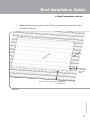
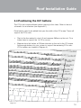
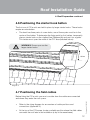
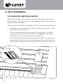
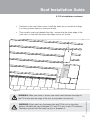
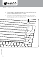
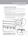
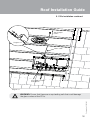
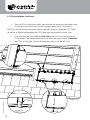
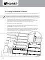
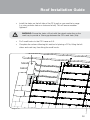
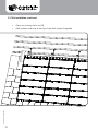
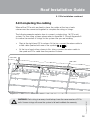
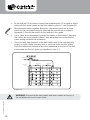
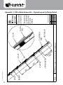
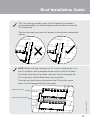
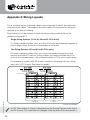
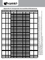
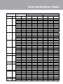
1
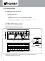
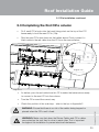
Roof Installation Guide
& Warranty
C21e Slate
For new builds and re-roofing with C21e Slate type M50-S39
Part number: 15195-01
On completion please return this guide to the Commissioning Electrician
Revision: 01
© Solarcentury 2012
Installation Details
Please complete the information below.
Once the installation has been completed, this guide should be passed to the
Electrician who will be responsible for commissioning the system.
Installation address:
String voltage checks taken at:
Date
/
Checks taken by:
Company Name
/
Time
:
Last Name
First Name
Part number: 15195-01
Contact Number
Notes:
• Within this guide the illustrations show an 18 unit C21e system, using 600mm x 300mm slates. Layouts for other slate sizes are provided in the appendices.
• The C21e solar electric roof slate will be referred to as a C21e or a C21e unit throughout.
Roof Installation Guide
Contents
Title.....................................................................Page
2. Components................................... 3
2.1 Equipment required................. 3
2.2 The C21e Slate carton............. 3
2.3 The roof accessories box......... 4
3. Pre-Installation Checks.................. 5
4. Roof Preparation............................ 6
4.1 General recommendations....... 6
4.2 Marking the area for the
C21e system........................... 7
4.3 Laying the bottom
slate courses........................... 9
4.4 Positioning the C21e battens... 10
4.5 Removing conflicting battens... 11
4.6 Positioning the starter hook
batten...................................... 12
4.7 Positioning the field cables ...... 12
5. C21e Installation............................. 13
5.1 Laying the right hand
section..................................... 13
5.2 Fitting the first C21e Slate........ 16
5.3 Completing the first
C21e column........................... 20
5.4 Fixing the top C21e in
a column ................................ 22
5.5 Checking the C21e
cable connections ................... 23
5.6 Laying a middle C21e
column.................................... 24
5.7 Laying the final C21e
column.................................... 25
5.8 Completing the cabling............ 28
6. Completing the C21 Array.............. 30
7. Disclaimer of Liability..................... 31
8. Warranty.......................................... 32
Appendices......................................... 35
Appendix 1: C21e Slate schematic
- typical layout & fixing
detail.............................. 35
Appendix 2: Soak tray
installation tips.............. 37
Appendix 3: String layouts................ 39
Appendix 4: String checker
user guide...................... 40
Appendix 5: Component list
and roof dimensions...... 41
Part number: 15195-01
1. Health and Safety........................... 1
1.1 General guidance..................... 1
1.2 Electrical hazards..................... 1
1.3 Preparation for C21e
installation............................... 2
1. Health and Safety
1.1 General guidance
•
Construction (Design and Management) Regulations 2007 (CDM)* and
general construction site training must be followed.
•
Safe working at heights training should be adhered to.
•
Anyone handling photovoltaic (PV) modules should be trained in the correct
manual handling practice.
•
All appropriate Health and Safety regulations should be followed correctly.
•
Avoid installing the system in poor weather conditions, including strong
wind, rain, ice or snow.
•
The slate courses should be layed according to British Standard 5534:
2003* ‘Code of practice for slating and tiling (including shingles)’ unless
instructed otherwise.
•
Install all components as specified within this guide to ensure a weather
tight finish and a valid warranty.
1.2 Electrical hazards
You must be aware of the following:
WARNING: PV modules produce a DC voltage whenever exposed to light.
This voltage cannot be switched off.
Part number: 15195-01
WARNING: Care must be taken not to cut or damage cable insulation or
expose bare wire.
•
PV modules are pre-wired with touch-proof connectors to prevent an
electrical shock during general handling.
•
All work must be carried out with the C21e system disconnected from the
mains electrical supply.
•
PV modules do not present a risk as long as appropriate safety practices
are followed at all times during installation.
1
*latest at time of print
Roof Installation Guide
1. Health and Safety continued
1.3 Preparation for C21e installation
•
Use this installation guide alongside your system design guide and roof schematic (see Appendix 1) to determine the location and layout of the
C21e system on the roof.
•
Use this installation guide alongside the string diagram (see Appendix 3) to understand the cabling and their connections on the roof.
•
Ensure all cable connectors are dry and free of dirt before making connections.
•
Ensure no cable ends are left exposed to the weather during work breaks
or after completion of works. Keep the C21e units in a weatherproof
environment before installation.
•
Carry the C21e units with both hands by the frame, and avoid scratching
the glass.
•
Only load as many C21e units onto the roof as you expect to install during
the session.
•
Secure or remove any uninstalled units before leaving the roof to avoid
possible wind damage.
•
Do NOT walk on the glass surface of the C21e units. While robust, extreme
point pressure may cause the toughened glass laminate to shatter.
•
Do not leave tools or unsecured materials above the C21e installation area,
to avoid potential damage to the units.
Part number: 15195-01
Follow the guidance below to ensure the C21e units are installed and handled
correctly:
2
2. Components
2.1 Equipment required
•
Standard roofing tool kit
•
C21e specific tools:
- Screwdriver (with Torx T20 drive supplied with this guide).
- String checker including specialist touch proof test leads to check cable connections (available to order from Solarcentury).
2.2 The C21e Slate carton
Each C21e carton contains six C21e units.
The C21e Slate has the following features:
1210mm
445mm
150mm
Junction box
Fixing holes
C21e cables
Grooves for hooks
Hook fixing point
Part number: 15195-01
PV cells
150mm to
junction box
Hook guide lines
Please note: for visual simplicity, photovoltaic cells have been removed on
subsequent diagrams in this guide.
3
Screw hole
(for top C21
row only)
Roof Installation Guide
2. Components continued
2.3 The Roof Accessories Box
When a complete system is ordered, it will include a Roof Accessories Box
containing the following components required for installing the C21e array:
Starter & Finish Pack
Small Hook Pack
195mm
62mm
4.8mm x
32mm
(silver)
4.8mm x
25mm
(black)
x3 starter hooks per C21e column.
Stainless steel screw with washer (Torx T20 drive).
Used with the starter hooks and to fix the top C21e
unit in each column.
x3 small hooks per C21e unit.
Stainless steel screw with washer (Torx T20 drive).
Used for all other C21e units.
150mm
150mm
430mm
10mm
Flexible C21e Soak Tray
(quantity specified at time of order)
Return Cables
(length is layout dependent, x1 cable per column)
Part number: 15195-01
Torx T20 drive
10m Field Cables
(x2 per string)
The quantities of components vary by system size and layout (see Appendix 5 for details).
4
3. Pre-Installation Checks
Before you go on to the roof, check that:
•
Your roof slates are compatible with the C21e units.
C21e Slate is compatible with natural slates
across a wide range of standard sizes, ranging
from 600mm x 300mm to 250mm x 150mm.
300 mm
600 mm
C21e Slate is also compatible with standard
fibre cement slates, including Marley (Eternit)
Rivendale, Garsdale, Birkdale and Thrutone.
Maximum slate thickness: 10mm
250 mm
Part number: 15195-01
150 mm
5
See the C21e datasheet, available at
www.solarcentury.com, for the up to date
list of compatible slates.
•
Your accessories box contains the correct number of parts needed for your
system size (see Appendix 5).
•
The C21e units, particularly the glass surfaces, are undamaged.
•
You have all the required tools including the string checker.
•
All relevant site requirements have been checked and adhered to (including
planning permission, building control or site rules).
•
The C21e units will be situated on a roof pitch facing south (between south
east and south west).
•
The C21e units will be positioned in an unshaded location.
•
You understand the roof schematic (see Appendix 1).
•
You understand the string layout (see Appendix 3).
•
You have read this guide in full.
Roof Installation Guide
4. Roof Preparation
4.1 General recommendations
•
We recommend you use a breathable roofing membrane, or similar.
•
Use 50 x 25mm tanalised battens nailed to rafters for the slates. Space
them as standard across the whole roof in accordance with BS 5534: 2003.
WARNING: For ‘warm roofs’ eaves to ridge ventilation (or equivalent)
should be provided to ensure adequate air flow behind the C21e units.
Space
according
to slate
specification
Roof
battens
Diagram 1
Part number: 15195-01
WARNING: Make sure there are no upstanding nails that could break the
glass on the C21e or damage the cables.
6
4. Roof Preparation continued
4.2 Marking the area for the C21e system
To make sure the C21e system is installed in the correct position on the roof,
you must mark the area out before you begin.
•
Refer to the Appendices and your Architect’s drawings to understand
which layout to use and where the system will be located on the roof.
Design Rules
The area that the C21e system will cover on the roof (Diagram 2) has been
calculated using the following design rules. These rules exist to ensure a
weathertight installation.
•
Lay the C21e units straight bond.
•
Allow a minimum of 2.5 slate widths between the edge C21e units and
the verges or equivalent obstruction (one conventional slate plus one
slate and a half).
•
Allow at least three courses of conventional slates below the C21e area,
and at least three courses of conventional slates above the C21e area.
•
Locate the system central on the roof and not close to any vents.
See Appendix 5 for further details of required space for each C21e system size.
Part number: 15195-01
Consult the Site Manager or System Designer if the drawings do not
conform to the above design rules.
The example C21e system in this guide uses 6 rows and 3 columns.
7
Roof Installation Guide
4. Roof Preparation continued
•
When the layout and location of the C21e system has been identified, mark
this area on the roof.
1e
C2
ea
Ar
e
lat
ea
Ar
S
At least 2.5
slate widths
from each
verge
Minimum start distance from ridge/eaves
= 3 slate courses
Part number: 15195-01
Diagram 2
8
4.3 Laying the bottom slate courses
•
Lay the bottom courses of conventional slates using standard practice. Start
from the eaves and continue up to the area marked for the C21e system.
•
Place a slate on the next course (shaded below) and chalk from the tail of the
slate across the width of the C21e area. This line is where the bottom edge of
the C21e units will sit.
rea
A
1e
C2
Part number: 15195-01
Diagram 3
9
Roof Installation Guide
4.4 Positioning the C21 battens
The C21e units require different batten spacing to the slates. Refer to the roof
schematic for an overview (see Appendix 1).
Extra battens need to be added that span the width of the C21e area. These will
support the C21e units.
•
Start at the line marked in step 4.3 and measure 380mm up the roof. Fix a
batten here to support the 1st C21e course.
•
Measure from this batten, at 300mm intervals up the roof in the C21e area.
Add enough battens for your system to support the remaining C21e units.
(C21e battens are shaded in Diagram 4.)
Slate batten
Shared C21e and slate batten
C21e batten
300mm
300mm
300mm
300mm
Diagram 4
Part number: 15195-01
380mm to top
of the batten
10
4. Roof Preparation continued
4.5 Removing conflicting battens
•
The junction box on the back of the C21e may interfere with some of the
slate battens. To avoid this, the slate battens should be cut out in the C21e
area to ensure the C21e units lay flat (Diagram 5).
Rafter
Diagram 5
WARNING: Make sure that all battens start and finish on a rafter for
adequate support.
Part number: 15195-01
WARNING: Make sure there are no upstanding nails that could break the
glass on the C21e or damage the cables.
11
Roof Installation Guide
4. Roof Preparation continued
4.6 Positioning the starter hook batten
The first row of C21e units are held in place by larger starter hooks. These hooks
require an extra batten.
•
The hook has three pairs of screw holes, one of these pairs must be in the
centre of the batten. To determine the fixing point for this batten, temporarily
place a starter hook on the chalked line (Diagram 6b) and use it as a guide.
This batten must span the width of the C21 area (hatched below).
WARNING: Ensure you use the
larger starter hooks.
195mm
Diagram 6b
Diagram 6
4.7 Positioning the field cables
•
Refer to the string diagram for an overview of cable positions and connections (Appendix 3).
•
At the top of the C21e area, locate a suitable position where the field cables
can enter the roof later in the installation (a lap in the membrane).
12
Part number: 15195-01
Before fixing the C21e units you must consider how the cables are connected and where they enter the roof space.
5. C21e Installation
5.1 Laying the right hand section
Slates need to be fitted up the right hand side of the C21e area. On each slate
batten a flexible C21e soak tray needs to be installed between the C21e unit and
the slate, as described below.
The soak trays will ensure that joins between C21e units and slates are weather-tight.
•
Install slates to the side of the C21e area as you would at a verge (i.e. using a
whole slate or a slate and a half).
•
Push a soak tray behind the slate, resting on the slate batten. It should be
positioned so that the raised centre ridge is on the right hand side and the
Solarcentury logo is on the bottom left (inset Diagram 7a).
•
The bottom of the soak tray should be in line with the tail of the slate, and the
raised centre line should sit flush with the slate edge. (The exposed half of the
soak tray, with the logo, will be covered by the C21e unit, shown in step 5.2.)
Diagram 7a
Raised ridge
Part number: 15195-01
Flexible
centre line
Diagram 7
13
Roof Installation Guide
5. C21e Installation continued
•
Continue on the next slate course; install the slates as you would at a verge
(i.e. using a whole slate or a slate and a half).
•
Then install a soak tray beneath the slate - ensure that the lower edge of the
soak tray is in line with the lower slate edge, and is not visible.
Diagram 8
WARNING: Edge soak trays (between slate and C21e) rest on the slate
battens. Middle soak trays (between C21 and C21) rest on the C21e battens.
Familiarise yourself with the soak tray tips in Appendix 2.
14
Part number: 15195-01
WARNING: Make sure there is at least one whole slate between the edge of
the C21e area and the verge of the roof (or equivalent obstruction).
5. C21e Installation continued
•
Continue laying the slates and soak trays in this column until you have one
soak tray on each slate batten in the C21e area.
•
Depending on the slate size and batten spacing you may need to add
one extra soak tray on the next batten, to provide adequate headlap. This
should be repeated on the final soak tray column.
Part number: 15195-01
Diagram 9
15
Roof Installation Guide
5. C21e Installation continued
5.2 Fitting the first C21e Slate
It is advised that the C21e units are laid column by column. This allows the C21e
cables to be connected and tested as you go.
The first column of C21e units should begin on the lowest C21e batten and sit flush
with the slates on the right.
Three large starter hooks are used to secure the front of each C21e unit on the
bottom row. To position the hooks correctly:
•
Temporarily place a C21 in position on the first C21 batten. Leave a 10mm gap
between the C21 position and slate to allow the soak tray to bend (10a).
•
There are three guide lines on the front of the C21 frame (10a) that indicate the
starter hook positions. Mark these points on the slates (X on Diagram 10).
•
Remove the C21 and fix 3 starter hooks to the batten at the marked points (10b).
150mm
Starter hook
guide
10mm
Part number: 15195-01
Diagram 10a
Diagram 10
TIP: The screw holes must be in the
centre of the batten.
Diagram 10b
16
5. C21e Installation continued
WARNING: Only use the hooks, screws and washers supplied. These form
part of the system designed to provide a weather-tight seal and are correctly
sized for the C21e units. Using any others will invalidate the warranty.
Use the correct quantity every time.
•
Rest the first C21e face down as shown in Diagram 11 and pass both C21e
cables under the batten.
•
Firmly connect the black C21e cable to the end of a return cable (Diagram
11a).
•
Pass the length of the return cable under the battens to the top of the
column.
TIP: The longer field cables (that enter the roof space) look similar to
the return cables. To help distinguish between them, the return cables
have a red tag and the field cables are marked with one of the following
symbols:
Part number: 15195-01
WARNING: Make sure there is no gap between any connectors as this will
cause the system to fail. To ensure a firm connection, push the connectors
together until they click.
17
Roof Installation Guide
5. C21e Installation continued
Take to top of
column
Diagram 11a
Return cable
Black C21e cable
C21e cables passed
under batten
Diagram 11
Part number: 15195-01
WARNING: Ensure that there are no upstanding nails that could damage
the glass surface of the C21e.
18
5. C21e Installation continued
•
Turn the C21e round the correct way with the nib resting on the batten, and
clip the grooves at the front into the 3 large starter hooks (12a and b).
The C21e should cover the exposed half of the right soak tray (Diagram 12). There
should be a 10mm gap between the C21e and right slate (previous inset 10a).
•
Fit a soak tray half way under the left side of the C21e unit resting on the
C21e batten. The raised centre line of middle soak trays should sit beneath
the C21e on the right, and the Solarcentury logo is on the left (12c).
Diagram 12c
Part number: 15195-01
Hook
guides
Diagram 12b
19
Diagram 12
Diagram 12a
Roof Installation Guide
5. C21e Installation continued
5.3 Completing the first C21e column
•
Fix 3 small C21e hooks into the hook fixing points on the top of the C21
frame ready to hold the next C21e (13a).
•
Rest the next C21e face down on the batten above. Firmly connect its
black cable to the red cable from the C21e on the course below.
Diagram 13a
Diagram 13
•
As before, pass the red cable from this C21e under the batten above ready
to connect to the next C21e in the column.
•
Turn the C21e round the correct way.
•
Check the position of the soak trays - refer to the tips in Appendix 2.
Part number: 15195-01
WARNING: Ensure that there is no risk of the cables being trapped or
pierced when the C21e unit is fixed.
WARNING: Make sure that when the Return Cables and C21e cables
are pushed up the roof they lie close to each other. This is important
throughout the installation to prevent electrical interference.
20
5. C21e Installation continued
•
Clip the front edge of the C21e unit into the small C21e hooks. Make sure
that the hooks align with the guide lines on the front and sit in the grooves
on the back (Diagram 14a).
•
Place another soak tray half way under the left side of this C21e. It should
sit over the frame of the C21e on the course below (14b).
•
Screw in three small C21e hooks ready for the next C21e (Diagram 14c).
Diagram 14b
Diagram 14c
Part number: 15195-01
Diagram 14
Diagram 14a
21
Roof Installation Guide
5. C21e Installation continued
•
Complete the column by repeating this process. Remember to use the small
C21e hooks, connect the cables, insert a left soak tray and check the right
soak trays as you go.
5.4 Fixing the top C21e in a column
•
Use 4 of the smaller 4.8 x 25mm screws provided in the Starter & Finish
Pack to fix the C21 unit at the top of the column. Use the screw holes
(15a), to prevent the conventional slates in the next course from kicking up.
At the top of each column you should be left with the end of the Return Cable and the end of the red cable from the last C21e unit.
Return Cable
Red C21e Cable
Part number: 15195-01
Diagram 15a
Diagram 15
22
5. C21e Installation continued
5.5 Checking the C21e cable connections
•
At the top of each column, ensure that the C21e cables are left in an
accessible position. They will be connected later in the installation.
Solarcentury recommends that a string check is carried out for each column to
check the cable connections (Diagram 16).
•
To carry out a string check follow the instructions in Appendix 3 using the
string checker.
Part number: 15195-01
Diagram 16
WARNING: Always use safety leads with the string checker. To avoid risk of electrocution, never use standard meter probes.
23
Roof Installation Guide
5. C21e Installation continued
5.6 Laying a middle C21e column
To install a middle column of C21e units, return to the bottom and work
upwards.
Follow the method described in sections 5.2 to 5.5:
•
Position and fix the starter hooks on the starter hook batten (as 5.2).
•
Take a C21e and push both cables under the batten above. Connect the
black cable to a return cable and pass to the top of the column.
•
Turn the C21e round the correct way and clip it into the starter hooks.
•
Fit a soak tray to the left of the C21e unit on the C21e batten.
•
Follow steps from 5.3 to 5.5.
Part number: 15195-01
WARNING: For middle columns do NOT leave the 10mm gap between
each column of C21e units.
Diagram 17
24
5.7 Laying the final C21e column
To install the final column of C21e units next to the slate, follow the order below.
NOTE: In this column, fix the small hooks after laying the slates and soak tray.
•
Position and fix the starter hooks on the starter hook batten as 5.2.
•
Take a C21e and pass both cables under the batten above. Connect the
black cable to a return cable and pass to the top of the column.
•
Clip the C21e into the starter hooks.
•
Position the soak tray behind the slate so that the Solarcentury logo is on
the top right, and under the C21e unit (18a).
•
Keep the soak tray behind the C21e. The bottom of the soak tray should be
in line with the tail of the C21e, and the centre line should sit flush with the
C21e edge (Diagram 18). The exposed half of the soak tray will be covered by the slate (18a).
10mm
Part number: 15195-01
Diagram 18a
Diagram 18
25
Roof Installation Guide
•
Install the slates on the left side of the C21e unit as you would at a verge
(i.e. using a whole slate or a slate and a half). This will ensure weather
tightness.
WARNING: Ensure the slates sit flush with the raised centre line on the
soak tray to provide a 10mm gap between the C21e and slate (18a).
Fix 3 small hooks to the C21 frame as 5.3.
•
Complete the column following this method of placing a C21e, fitting the left
slates and soak tray, then fixing the small hooks.
Part number: 15195-01
•
Diagram 19
26
5. C21e Installation continued
•
Carry out a string check as 5.5.
•
Add an extra soak tray at the top of the final column if required.
Part number: 15195-01
Diagram 20
27
Roof Installation Guide
5. C21e Installation continued
5.8 Completing the cabling
When all the C21e units are fixed in place, the cables at the top of each
column must be connected together to complete the string or strings.
The following example explains how to connect a single string, 18 C21e unit
system. For two string systems please refer to Appendix 3. Consult Appendix 5
to confirm the number of strings for the system size you are installing.
•
Start at the right hand C21e column. At the top, connect the return cable to
a field cable (marked with one of the symbols
).
•
At the top of each other column in this string, connect the return cable to
the spare red C21e cable from the previous column.
Field Cable
Field Cable
Red
C21e Cable
(column 3)
Return Cable
(column 3)
Red
C21e Cable Return Cable
(column 2)
(column 2)
Red
C21e Cable Return Cable
(column 1) (column 1)
Diagram 21
Part number: 15195-01
WARNING: Each string in an array should always have the same number of C21e
units. Uneven strings will cause the system to fail and invalidate the warranty.
28
•
At the final left C21e column connect the remaining red C21e cable to a field
C21esame symbol as the field cable in column 1 (see Diagram 22).
cable withRedthe
cable
•
Bring the field cables together above this column and carry out a string
check for the completed string by following the instructions provided in
Appendix 3. Record the results on the reverse of this guide.
•
Use a cable tie (or equivalent) to fasten the cables to the battens. Securing
the cables will avoid potential stress if they are pulled from within the loft
space during the electrical installation.
•
Once secured, take the ends of the field cables and fit the supplied plug
covers to protect them from any dust or moisture within the roof space.
Push the cable ends through a lap in the membrane at the top of the final
column and into the loft space (as identified in step 4.7).
Red C21e cable
ble
Red C21e
cable
Red C21e
cable
Red C21e
cable
Diagram 22
Part number: 15195-01
WARNING: Ensure that the field cables and return cables at the top of
the installation lie close to each other.
Red C21e
cable
29
Red
C21e cable
Red C21e cable
Red C21e
cable
Roof Installation Guide
6. Completing the C21 Array
When all the C21e units have been fitted, a string check for the system is complete,
and the Field Cables passed into the loft space, the remaining slates can be laid.
•
Lay an eaves course of slates on the batten above the C21e units.
•
Continue laying the slates for the remainder of the roof using standard
practice.
WARNING: Take care not to drop tools or materials on the C21e units.
NOTE: Please remember to dispose all unused materials safely,
and recycle where possible.
30
Part number: 15195-01
Diagram 23
7. Disclaimer of Liability
Instructions given in this guide are general guidelines only for the design,
installation and use of the C21e units together with any associated components.
Due to the wide variety of materials, equipment and sites which an installation may
involve this guide cannot consider the individual technical requirements relevant to
every individual project and/or site.
If you have detailed questions about any specific project and/or site please contact
Solarcentury.
Before installing the C21e units, contact the appropriate authorities to determine
the permissions, consents, approvals, licenses, installation and inspection
requirements which apply to the site and the installation. Solarcentury accepts no
responsibility or liability in this respect.
This guide is based on Solarcentury’s knowledge and experience and is believed to
be reliable but the guide does not constitute a warranty, express or implied.
Solarcentury does not assume responsibility and expressly disclaims liability for
any loss, damage or expense arising out of or in any way connected with incorrect
handling, installation, operation, use or maintenance of the C21e units.
No responsibility is assumed by Solarcentury for any infringement of patents or
other rights of third parties that may result from use of the C21e units. No license is
granted by implication or otherwise under any patent or patent rights.
Solarcentury reserves the right to make changes to the Product, the specifications
or this guide, without prior notice.
Incorrect and/or faulty installation, operation, use or maintenance may be
dangerous and may invalidate any warranty which may apply to the C21e units.
End users should remember that the C21e units require professional installation
using special tools and expert know-how.
Part number: 15195-01
No part of this guide may be reproduced in any form by any means without
Solarcentury’s express written consent.
31
Roof Installation Guide
8. Warranty
Product Warranty for C21e solar electric roof slates in United Kingdom and
Republic of Ireland
Model number: C21e Slate M50-S39
This warranty applies to the Solarcentury Modules with the model numbers listed
above which were purchased from Solarcentury or an authorised distributor, installer
or reseller (an “Authorised Distributor”) and purchased and installed in the territory
indicated above.
In this warranty “Product” means each of the listed Modules individually.
In addition to your statutory rights, which are unaffected, Solarcentury guarantees that,
from the date of original purchase from Solarcentury or its Authorised Distributor (or, in
the absence of proof of purchase, from the date of manufacture):
A Materials and Workmanship – 10 years
The Product shall be free from defects in materials and workmanship in
manufacture for a period of 10 years.
B Power Output – 25 years
(1) The power rating of the Product will remain at 90% or more of its Peak Power
rating1 for 10 years; and
(2) The power rating of the Product will remain at 80% or more of its Peak Power
rating for 25 years.
If a Product fails to meet the standard guaranteed and the conditions below are
met, then Solarcentury will, in its sole discretion: (a) repair or replace the defective
Product with an equivalent product; or (b) refund the purchase price of the
Product; or (c) provide the owner with additional PV modules required to make
up the power lost or provide to the owner compensation for power lost up to a
maximum value of the purchase price of the Product, such loss in power having
been proved to have been suffered by the owner of the Product and determined
by Solarcentury (in its sole and absolute discretion) to be due to defects in
materials or workmanship.
Part number: 15195-01
Notwithstanding the above, if the Product is used in any non-land based
applications, any Power Output warranty claims must be made within 10 years.
In this context, the power rating of the Product will be that measured by or on behalf of Solarcentury under
Standard Test Conditions (irradiance of 1000W/m2, light spectrum AM 1.5g and a cell temperature of 25
degrees Celsius) and may not equate to that produced by the Product under other conditions. The relevant
“Peak Power” is defined in Solarcentury’s Datasheet at the time of shipment.
1
32
8. Warranty continued
Solarcentury shall have no liability for any other costs or losses howsoever arising
(and for the avoidance of doubt) this guarantee does not include the costs of labour
or transport or any other associated costs including, without limitation, costs involved
in removing or returning the Product to Solarcentury, or its re-installation. Any Product
(or parts) replaced shall become the property of Solarcentury and the replacement
Product shall only have the warranty cover for the remainder of the original warranty
period.
The conditions:
(a)
(b)
(c)
(d)
(e)
(f)
(g)
(h)
(i)
Part number: 15195-01
(j)
(k)
33
The Product is properly installed in a suitable location in accordance with
Solarcentury’s Datasheets and instructions for design, installation, operation
and maintenance of the Product (together the “Product Guide”) and in
accordance with all applicable laws and standards as updated and applicable
at the date of installation whether or not those standards are identified in the
Product Guide;
The Product has not been removed from the location in which it was first
installed, nor connected to, or used with, any unapproved device;
The Product has not, in Solarcentury’s absolute judgment, been damaged
during transportation, delivery, storage, handling or installation;
The Product has not, in Solarcentury’s absolute judgment, suffered damage
caused by extraneous causes such as structural movement of the roof,
accident, an impact of significant force, fire, lightning, flood, severe weather,
interference by animals, insect and pest infestation or other Acts of God or
other events, howsoever caused, reasonably beyond Solarcentury’s control;
The Product has not been subject to misuse, neglect, abuse, alteration or
improper application;
The Product has not been exposed to conditions (including, where applicable,
excessive levels of pollution or wind speeds) at the property where it was
installed which are more adverse than those which the Product is designed to
withstand as stated in the Product Guide;
The Product has been operated and maintained in accordance with the
Product Guide;
The labels, serial numbers or barcodes on the Product or any of its
components have not been altered, removed or made illegible;
Any alleged defect in materials is not merely cosmetic or due to normal and
reasonable wear and tear of the Product;
Solarcentury has been paid in full for the Product;
A claim is notified: (i) in accordance with the procedure set out below, and as
set out in the Product Guide; (ii) within the applicable warranty period set out
above; and (iii) within two months of the first date on which problems with the
Product were detected or ought to have been detected.
Roof Installation Guide
8. Warranty continued
If any of the above conditions are not met then Solarcentury shall have no obligations
under this guarantee and no rights shall accrue as a result of this warranty.
Procedure for making a claim:
Before making a claim, you should review the Product Guide to make sure that you
have followed all the guidance.
If after reviewing the Product Guide you are still concerned that the Product is not
performing as it should, please contact your installer or maintainer in the first instance.
If your installer or maintainer considers the Product is not performing according to the
warranty, please (together with the assistance of your installer or maintainer) provide
Solarcentury with the details below so that we can consider your claim, marking your
correspondence for the attention of the Solarcentury Customer Services. Please
include:
•
Confirmation that you have reviewed the Product Guide but the results
indicate that the Product may be failing to perform to the guaranteed
standard;
•
Confirmation that conditions (a) to (k) above are met;
•
A detailed description of the Product failure, including supporting images;
•
Adequate documentation of proof of purchase (including details of purchase
receipts);
•
The Product’s serial number; and
•
Details of when and by whom the Product was purchased and installed and
the address of the property at which it was installed.
Part number: 15195-01
Solar Century Holdings Limited
91-94 Lower Marsh
London SE1 7AB
020-7803-0180
[email protected]
34
35
.0
DRAWING NAME:
300
STARTER HOOK BATTEN
0A C21E SLATE INSTALL SCHEMATIC - SLATE SIZES 600 x 300MM AT 250MM GAUGE
RÉV :
.0
14185-00
300
C21e BATTENS
C21e SLATE
E
T
SLA
D
R
A
ND GE
STA GAU
DRAWING NO:
MEMBRANE
RAFTERS
Part number: 15195-01
C21e HOOK
(SMALL)
TRADITIONAL SLATE
C21e STARTER HOOK
(LARGE)
C21e SLATE
SHEET:
SCALE
DATE :
DRAWN:
CHECKED:
NTS
N/A
MW
01/07/11
MJK
This drawing is to show the use of
Solarcentury Holdings Ltd products.
PLEASE REFER TO THE
C21e SLATE DATASHEET
FOR THE FULL RANGE
OF SLATE SIZES
SUPPORTED.
NOTES :
EXAMPLE LAYOUT WITH
600 X 300MM SLATES.
Appendix 1: C21e Slate Schematic - Typical Layout & Fixing Detail
REV:
DRAWING NAME:
SOAK TRAY
C21e SLATE
0A C21E SLATE INSTALL SCHEMATIC - SLATE SIZES 600 X 300MM AT 250MM GAUGE
Part number: 15195-01
14185-00
DRAWING NO:
STARTER HOOK BATTEN C21e STARTER
HOOK (LARGE)
C21e BATTEN
SLATE BATTENS
C21e HOOK
(SMALL)
SHEET:
SCALE
DATE :
DRAWN:
CHECKED:
N/A
NTS
MW
01/07/11
MJK
This drawing is to show the use of
Solarcentury Holdings Ltd products.
PLEASE REFER TO THE
C21e SLATE DATASHEET
FOR THE FULL RANGE
OF SLATE SIZES
SUPPORTED.
NOTES :
EXAMPLE LAYOUT WITH
600 X 300MM SLATES.
Roof Installation Guide
36
Appendix 2: Soak Tray Installation Tips
WARNING: C21e Soak Trays should NEVER extend onto the glass surface of
the C21e unit, or the cells will be shaded, voiding the warranty.
TIP: Edge soak trays on the far right and left of the array (between C21e unit
and slates) can sit under or over the C21e frame. Having some soak trays
below and some above the C21e frame will manage the flow of any water.
The soak trays should always remain aligned with the bottom of the slates, and
positioned so that the Solarcentury logo is always under the C21e unit.
TIP: It is advised that you position the soak tray over the frame of the C21, if
this can be done without obscuring the laminate (a).
If the soak tray covers the C21e laminate, as shown in Diagram b, you should
trim the soak tray (c):
Part number: 15195-01
Diagram a
Diagram b
37
Diagram c
Roof Installation Guide
TIP: If the soak tray partially covers the C21e frame (d), and there is
not enough headlap, you should bring the soak tray down to cover the
C21e frame fully.
Then trim the soak tray corner so it remains in line with the conventional
slate (e).
Diagram d
Diagram e
NOTE: Middle soak trays between two C21e units should always sit on
the C21e battens, and be aligned with the bottom of the C21e frame.
The raised centre line of the middle soak trays should sit beneath the
C21 on the right, with the Solarcentury logo on the left.
The soak tray should be over the frame of the C21e on the course
below. This will manage the flow of any water.
Over left soak tray
Part number: 15195-01
Over C21e frame below
38
Appendix 3: String Layouts
For all standard layouts, individual columns are connected in exactly the same way
using the return cables. The length of the return cable will correspond to the layout
selected at the time of ordering.
Final connection of the columns to form the string or strings should follow the
guidance in Appendix 4.
Single String Systems
(12 to 36,
48 and Red
54C21eC21e units)
Red C21e
Red C21e
Red C21e
cable
cable
cable
cable
Red C21e
For these
standard system sizes, all of the C21e units are connected together to
cable
form a single string,
in the example in this guide.
30as shown24
29
23
28
22
24
19
Red C21e
cable
Two String Systems (42 and 60 to 80 C21e units)
For these standard27system sizes,
21 two strings are needed irrespective of the
physical roof layout.
For all two
string systems you should consider the C21e
26
20
units as two separate arrays, with an equal number of C21e units in each array.
For example, a system of 36 C21e units should be split evenly into two strings,
each with 18 C21e units. See below for details.
Red
C21e cable
Red C21e cable
18
17
17
16
16
15
15
14
14
13
13
2nd String
Part number: 15195-01
Red C21e cable
18
Red C21e
cable
1st String
36 C21e unit example
NOTE: The number of strings is dependent on the System Design for the size of
the C21e array. This should not be changed. (See Appendix 5 for more details.)
Red C21e
cable
39
Red C21e
cable
Red C21e
cable
Roof Installation Guide
Appendix 4: String Checker User Guide
1. Connect the red test lead to the V’Ω input
connector (1) and the black test lead to the
COM input connector (2).
2. From the off position, turn the centre dial
one place in an anti-clockwise direction.
The Function Range is now set to 600Vdc (3).
3. Connect the opposite ends of the test leads
to the output strings of the C21e tile or slate.
Note the connectors will only connect one way.
4. The display will now read the DC voltage
produced by the C21e Units.
3.
600Vdc
5. The voltage will vary on the amount of
daylight falling on the C21e Units. Please refer
to the table as an approximate guide to the
measurement.
6. If the value displayed on the String Checker
screen is below the figure for an overcast day
then there is an error with the installation and
string connection.
7. In this situation, retrace the string connection
through from the start ensuring the connectors
are pushed firmly together with no gaps and that
the C21e Units follow the Stringing Diagram for
the given layout.
8. Once the reading is correct, switch the String
Checker to the OFF position.
2.
COM input
connector
1.
V ’Ω input
connector
Part number: 15195-01
9. You can now disconnect the test leads and
continue with the C21e installation following the
C21e On Roof Installation Guide.
Please refer to the user manual for full operating instructions.
String checkers with touch proof test leads are available to order from Solarcentury.
40
C21e Layout
Option(1)
C21e System Size
Number of
C21e Units
kWp
Strings
12
0.60
1
18
0.90
1
24
1.20
1
30
1.50
1
36
1.80
1
42
2.10
2
48
2.40
1
54
2.70
1
60
3.00
2
66
3.30
2
72
3.60
2
78
3.90
2
80
4.00
2
41
Rows
Columns
12
6
4
3
2
1
18
9
6
3
2
1
12
8
6
4
3
2
15
10
6
5
3
2
18
9
6
3
2
7
3
12
8
6
4
3
9
3
15
10
6
5
3
11
18
12
9
6
4
13
20
10
1
2
3
4
6
12
1
2
3
6
9
18
2
3
4
6
8
12
2
3
5
6
10
15
2
4
6
12
18
6
14
4
6
8
12
16
6
18
4
6
10
12
20
6
4
6
8
12
18
6
4
8
Standard Roof Components Provided
(For slate gauges below 200mm additional soak trays will be needed)(2)
Return Cables Qty(4) Soak C21e Starter C21e Hooks Pairs of Field
x Length (m)
Trays(3) Hooks (large)
(small)
Cables
1 x 4.5m
40
3
2 x 3m
30
6
3 x 2m
30
9
36
1
4 x 2m
20
12
6 x 2m
20
18
n/a
20
36
1 x 6m
60
3
2 x 4.5m
40
6
3 x 3m
40
9
54
1
6 x 2m
30
18
9 x 2m
30
27
n/a
30
54
2 x 4.5m
50
6
3 x 3m
50
9
4 x 3m
40
12
72
1
6 x 2m
40
18
8 x 2m
40
24
12 x 2m
30
36
2 x 6m
70
6
3 x 4.5m
60
9
5 x 3m
50
15
90
1
6 x 2m
50
18
10 x 2m
40
30
15 x 2m
40
45
2 x 6m
80
6
4 x 4.5m
60
12
6 x 3m
50
18
108
1
12 x 2m
50
36
18 x 2m
50
54
6 x 3m
60
18
126
2
14 x 2m
50
42
4 x 4.5m
80
12
6 x 3m
70
18
8 x 3m
70
24
144
1
12 x 2m
60
36
16 x 2m
60
48
6 x 4.5m
80
18
162
1
18 x 2m
70
54
4 x 6m
100
12
6 x 4.5m
90
18
10 x 3m
80
30
180
2
12 x 2m
80
36
20 x 2m
70
60
6 x 4.5m
90
18
198
2
4 x 6m
110
12
6 x 4.5m
100
18
8 x 4.5m
100
24
216
2
12 x 3m
90
36
18 x 2m
90
54
6 x 4.5m
110
18
234
2
4 x 10m
130
12
252
2
8 x 4.5m
110
24
Notes: (1) Additional layouts may be possible for some system sizes, but require additional Soak Trays and Return Cables to those provided in the Standard Systems.
(2) The components provided in each system will support the layouts as shown, a small quantity of spare screws and hooks are included.
(3) The standard quantity of Soak Trays provided will support conventional slate set out at a gauge down to 200mm. For narrower gauges
additional Soak Trays will be required.
(4) One Return Cable is provided per C21e Column. The cable length is dependent on the number of C21e rows in the layout, as shown.
(5) The dimensions stated are for guidance and are based on the C21e Design Rules for the range of approved slate sizes as stated on the product datasheet.
Please refer to the C21e Slate datasheet for full specification details.
Appendix 5: Component List and Roof Dimensions
Roof Installation Guide
C21e System Size
Number of
C21e units
kWp
12
0.60
18
0.90
24
1.20
30
1.50
36
1.80
42
2.10
48
2.40
54
2.70
60
3.00
66
3.30
72
3.60
78
3.90
80
4.00
(5)
Dimensions of C21 Array Total Roof Dimensions Required (including the slate border for example slate sizes )
(excluding slate border)
500 x 250mm (at 200mm gauge)
600 x 300mm (at 250mm gauge)
Length (m)
Width (m)
Length (m)
Width (m)
Area (m2)
Length (m)
Width (m)
Area (m2)
3.60
1.80
1.20
0.90
0.60
0.30
5.40
2.70
1.80
0.90
0.60
0.30
3.60
2.40
1.80
1.20
0.90
0.60
4.50
3.00
1.80
1.50
0.90
0.60
5.40
2.70
1.80
0.90
0.60
2.10
0.90
3.60
2.40
1.80
1.20
0.90
2.70
0.90
4.50
3.00
1.80
1.50
0.90
3.30
5.40
3.60
2.70
1.80
1.20
3.90
6.00
3.00
1.21
2.42
3.63
4.84
7.26
14.52
1.21
2.42
3.63
7.26
10.89
21.78
2.42
3.63
4.84
7.26
9.68
14.52
2.42
3.63
6.05
7.26
12.10
18.15
2.42
4.84
7.26
14.52
21.78
7.26
16.94
4.84
7.26
9.68
14.52
19.36
7.26
21.78
4.84
7.26
12.10
14.52
24.20
7.26
4.84
7.26
9.68
14.52
21.78
7.26
4.84
9.68
4.80
3.00
2.40
2.10
1.80
1.50
6.60
3.90
3.00
2.10
1.80
1.50
4.80
3.60
3.00
2.40
2.10
1.80
5.70
4.20
3.00
2.70
2.10
1.80
6.60
3.90
3.00
2.10
1.80
3.30
2.10
4.80
3.60
3.00
2.40
2.10
3.90
2.10
5.70
4.20
3.00
2.70
2.10
4.50
6.60
4.80
3.90
3.00
2.40
5.10
7.20
4.20
2.46
3.67
4.88
6.09
8.51
15.77
2.46
3.67
4.88
8.51
12.14
23.03
3.67
4.88
6.09
8.51
10.93
15.77
3.67
4.88
7.30
8.51
13.35
19.40
3.67
6.09
8.51
15.77
23.03
8.51
18.19
6.09
8.51
10.93
15.77
20.61
8.51
23.03
6.09
8.51
13.35
15.77
25.45
8.51
6.09
8.51
10.93
15.77
23.03
8.51
6.09
10.93
11.81
11.01
11.71
12.79
15.32
23.66
16.24
14.31
14.64
17.87
21.85
34.55
17.62
17.57
18.27
20.42
22.95
28.39
20.92
20.50
21.90
22.98
28.04
34.92
24.22
23.75
25.53
33.12
41.45
28.08
38.20
29.23
30.64
32.79
37.85
43.28
33.19
48.36
34.71
35.74
40.05
42.58
53.45
38.30
40.19
40.85
42.63
47.31
55.27
43.40
43.85
45.91
5.10
3.30
2.70
2.40
2.10
1.80
6.90
4.20
3.30
2.40
2.10
1.80
5.10
3.90
3.30
2.70
2.40
2.10
6.00
4.50
3.30
3.00
2.40
2.10
6.90
4.20
3.30
2.40
2.10
3.60
2.40
5.10
3.90
3.30
2.70
2.40
4.20
2.40
6.00
4.50
3.30
3.00
2.40
4.80
6.90
5.10
4.20
3.30
2.70
5.40
7.50
4.50
2.71
3.92
5.13
6.34
8.76
16.02
2.71
3.92
5.13
8.76
12.39
23.28
3.92
5.13
6.34
8.76
11.18
16.02
3.92
5.13
7.55
8.76
13.60
19.65
3.92
6.34
8.76
16.02
23.28
8.76
18.44
6.34
8.76
11.18
16.02
20.86
8.76
23.28
6.34
8.76
13.60
16.02
25.70
8.76
6.34
8.76
11.18
16.02
23.28
8.76
6.34
11.18
13.82
12.94
13.85
15.22
18.40
28.84
18.70
16.46
16.93
21.02
26.02
41.90
19.99
20.01
20.92
23.65
26.83
33.64
23.52
23.09
24.92
26.28
32.64
41.27
27.05
26.63
28.91
38.45
48.89
31.54
44.26
32.33
34.16
36.89
43.25
50.06
36.79
55.87
38.04
39.42
44.88
48.06
61.68
42.05
43.75
44.68
46.96
52.87
62.86
47.30
47.55
50.31
42
Part number: 15195-01
Notes:
43
Roof Installation Guide
Part number: 15195-01
Notes:
44
String Check Results
Use the tables below to record the string voltages.
Once completed, this installation guide should be passed to the Electrician who will be
responsible for commissioning the system.
String Checker Voltage Measurement Table
Voltage per string
on Sunny Day
Voltage per string
on Overcast Day
System Size (total
number of C21e
units in the system)
Number of
Strings
Number of C21e
Slates in each
String
12
1
12
137
109
18
1
18
205
164
24
1
24
274
219
30
1
30
342
274
36
1
36
205
164
42
2
21
239
192
48
1
48
274
219
54
1
54
308
246
60
2
30
342
274
66
2
33
376
301
72
2
36
410
328
78
2
39
445
356
80
2
40
456
365
SUN
CLOUD
Your recorded measurements:
Weather conditions (please tick)
SUN
CLOUD
String 1
Part number: 15195-01
String 2
For technical product support,
please contact Solarcentury on
(0)20 7803 0115
[email protected]
For customer service support,
please contact Solarcentury on
(0)20 7803 0180
[email protected]