1
NeOn-project.org
NeOn: Lifecycle Support for Networked Ontologies
Integrated Project (IST-2005-027595)
Priority: IST-2004-2.4.7 – “Semantic-based knowledge and content systems”
D6.9.1 Specification of NeOn architecture and API V2
Deliverable Co-ordinator:
Walter Waterfeld
Deliverable Co-ordinating Institution:
Software AG (SAG)
Other Authors: Michael Erdmann, Thomas Schweitzer (Onto)
Peter Haase (UKarl)
Document Identifier:
NEON/2008/D6.9.1/v1.0
Date due:
February 29, 2008
Class Deliverable:
NEON EU-IST-2005-027595
Submission date:
February 29, 2008
Project start date:
March 1, 2006
Version:
V1.0
Project duration:
4 years
State:
Final
Distribution:
Public
2006–2008 © Copyright lies with the respective authors and their institutions.
Page 2 of 49
NeOn Integrated Project EU-IST-027595
NeOn Consortium
This document is a part of the NeOn research project funded by the IST Programme of the
Commission of the European Communities by the grant number IST-2005-027595. The following
partners are involved in the project:
Open University (OU) – Coordinator
Knowledge Media Institute – Kmi
Berrill Building, Walton Hall
Milton Keynes, MK7 6AA
United Kingdom
Contact person: Martin Dzbor, Enrico Motta
E-mail address: {m.dzbor, e.motta} @open.ac.uk
Universität Karlsruhe – TH (UKARL)
Institut für Angewandte Informatik und Formale
Beschreibungsverfahren – AIFB
Englerstrasse 28
D-76128 Karlsruhe, Germany
Contact person: Peter Haase
E-mail address: [email protected]
Universidad Politécnica de Madrid (UPM)
Campus de Montegancedo
28660 Boadilla del Monte
Spain
Contact person: Asunción Gómez Pérez
E-mail address: [email protected]
Software AG (SAG)
Uhlandstrasse 12
64297 Darmstadt
Germany
Contact person: Walter Waterfeld
E-mail address: [email protected]
Intelligent Software Components S.A. (ISOCO)
Calle de Pedro de Valdivia 10
28006 Madrid
Spain
Contact person: Jesús Contreras
E-mail address: [email protected]
Institut ‘Jožef Stefan’ (JSI)
Jamova 39
SI-1000 Ljubljana
Slovenia
Contact person: Marko Grobelnik
E-mail address: [email protected]
Institut National de Recherche en Informatique
et en Automatique (INRIA)
ZIRST – 655 avenue de l’Europe
Montbonnot Saint Martin
38334 Saint-Ismier
France
Contact person : Jérôme Euzenat
E-mail address: [email protected]
University of Sheffield (USFD)
Dept. of Computer Science
Regent Court
211 Portobello street
S14DP Sheffield
United Kingdom
Contact person: Hamish Cunningham
E-mail address: [email protected]
Universität Koblenz-Landau (UKO-LD)
Universitätsstrasse 1
56070 Koblenz
Germany
Contact person: Steffen Staab
E-mail address: [email protected]
Consiglio Nazionale delle Ricerche (CNR)
Institute of cognitive sciences and technologies
Via S. Martino della Battaglia,
44 – 00185 Roma-Lazio, Italy
Contact person: Aldo Gangemi
E-mail address: [email protected]
Ontoprise GmbH. (ONTO)
Amalienbadstr. 36
(Raumfabrik 29)
76227 Karlsruhe
Germany
Contact person: Jürgen Angele
E-mail address: [email protected]
Food and Agriculture Organization
of the United Nations (FAO)
Viale delle Terme di Caracalla 1
00100 Rome
Italy
Contact person: Marta Iglesias
E-mail address: [email protected]
Atos Origin S.A. (ATOS)
Calle de Albarracín, 25
28037 Madrid
Spain
Contact person: Tomás Pariente Lobo
E-mail address: [email protected]
Laboratorios KIN, S.A. (KIN)
C/Ciudad de Granada, 123
08018 Barcelona
Spain
Contact person: Antonio López
E-mail address: [email protected]
D6.9.1 Specification of NeOn architecture and API V2
Page 3 of 49
Work package participants
The following partners have taken an active part in the work leading to the elaboration of this
document, even if they might not have directly contributed to the writing of this document or its
parts:
Ontoprise GmbH
Software AG
University Karlsruhe
Change Log
Version
Date
Amended by
Changes
0.4
12-03-2008
Walter Waterfeld
All topics covered except outlook
0.5
13-03-2008
Michael Erdmann
Many changes
0.6
15-03-2008
Walter Waterfeld
Revised architecture, introduction, conclusion
0.7
17-03-2008
Peter Haase
Revised naming
0.9
17-03-2008
Walter Waterfeld
Final version for internal Review
1.0
08-04-2008
Walter Waterfeld
Incorporated reviewer comments
…
Executive Summary
This deliverable is the successor of the first deliverable D6.4.1 on the specification of the NeOn
architecture and API. The intention is to incorporate first experiences with the NeOn toolkit in
general and with its usage in the NeOn case studies.
In favour of a clear focus in the first realisation of the NeOn toolkit ontology usage has not been
addressed specifically. Therefore this deliverable presents an enhanced architecture covering
those runtime aspects. Based on this enlarged architectural scope API specification have been
added. An additional focus was also the further utilization of the rich Eclipse infrastructure for the
API and extension points of the NeOn toolkit.
2006–2008 © Copyright lies with the respective authors and their institutions.
Page 4 of 49
NeOn Integrated Project EU-IST-027595
Table of Contents
1
Introduction ....................................................................................................................... 6
1.1
Relationship to other NeOn Toolkit deliverables ............................................................. 6
1.2
Experiences Use of NeOn Toolkit ................................................................................... 6
2
Architecture ....................................................................................................................... 8
2.1
General Approach for Integrating Ontology Engineering and Runtime ........................... 8
2.1.1
2.1.2
2.2
NeOn Toolkit for Ontology Engineering......................................................................... 15
2.2.1
2.2.2
2.2.3
2.2.4
2.2.5
2.3
Ontology Infrastructure Services..................................................................................... 16
Ontology Engineering Services....................................................................................... 17
GUI Level Components................................................................................................... 18
Other components........................................................................................................... 18
Essential Eclipse Plug-ins ............................................................................................... 19
Runtime Infrastructures ................................................................................................. 21
2.3.1
2.3.2
2.3.3
3
Lifecycle Activities for Ontology Engineering and Runtime .............................................. 8
A Generic Architecture for Ontology-based Information Systems with Lifecycle Support10
WTP based...................................................................................................................... 21
RAP Based Runtime Infrastructure ................................................................................. 23
Interoperability of NeOn Engineering Plug-ins and (Ontology) Web Services ............... 25
NeOn Toolkit API ............................................................................................................. 27
3.1
Core NeOn Toolkit Plug-ins........................................................................................... 27
3.1.1
3.1.2
3.1.3
3.2
Infrastructure Level APIs................................................................................................. 27
Engineering Level APIs................................................................................................... 28
GUI Level APIs................................................................................................................ 29
Support for developing NeOn plug-ins .......................................................................... 31
3.2.1
Using the NeOn Metamodel with the EMF, GEF and GMF Frameworks in Plugin
Development..................................................................................................................................... 31
3.3
Core Infrastructure Services.......................................................................................... 33
3.3.1
3.3.2
3.3.3
3.3.4
3.3.5
Reasoner Interface.......................................................................................................... 33
Extensibility of the Reasoner........................................................................................... 40
General Reasoner Service Interface............................................................................... 42
Registry Service .............................................................................................................. 44
Repository Service .......................................................................................................... 44
4
Conclusion....................................................................................................................... 45
5
References ....................................................................................................................... 46
6
Acronyms......................................................................................................................... 49
D6.9.1 Specification of NeOn architecture and API V2
Page 5 of 49
List of figures
Figure 1: Lifecycle Model .................................................................................................................. 8
Figure 2: Abstract Architecture ....................................................................................................... 11
Figure 3: The plug-ins of the basic NeOn toolkit............................................................................. 16
Figure 4: WTP Subproject Scopes.................................................................................................. 21
Figure 5: WTP Architecture............................................................................................................. 22
Figure 6. RAP Architecture (right) compared to traditional RCP architecture (left) ........................ 24
Figure 7: Ontomodel Plugin Architecture ........................................................................................ 31
Figure 8: Components and models used during the GMF-based development of OntoModel ....... 32
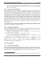
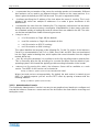
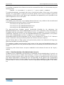
Figure 9: The configuration tab of the administration console. ....................................................... 35
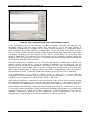
Figure 10: The Setting tabs of the Administration console ............................................................. 36
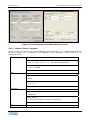
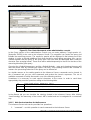
Figure 11: The client-side aspects of the administration console ................................................... 39
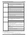
Figure 12: Visualization of WSDL for operations and SOAP bindings of the Inference Server ...... 40
2006–2008 © Copyright lies with the respective authors and their institutions.
Page 6 of 49
NeOn Integrated Project EU-IST-027595
1 Introduction
Since the availability of the NeOn toolkit last year a lot of experiences and feedback are available
now. Based on these experiences this deliverable enhances the NeOn architecture and API
definitions. They have been gathered in a parallel update of the NeOn toolkit requirements
[Aranda2008].
The NeOn project has concentrated in the first phase on the NeOn Toolkit as the Eclipse-based
development infrastructure for Ontology engineering. Traditional IT applications have a very sharp
distinction between development environment and the runtime environment. This is not the case
for semantic applications. The functionality of many components is usable in the development and
in the runtime environment. A major reason is that ontologies as the major modelling artefacts are
directly executable by a reasoner. This contrasts with traditional IT applications where UML
documents as modelling artefacts have to be transformed to source code, which has again to be
transformed to binary components before it can be executed at runtime.
Due to different performance and architectural characteristics the runtime support of semantic
application is still a very important aspect of the infrastructure.
1.1
Relationship to other NeOn Toolkit deliverables
This deliverable is an update of the deliverable D6.4.1 – specification of the NeOn reference
architecture and NeOn APIs. It contains changes and additions to the NeOn architecture and API.
Most of them were triggered from the first experiences with the available NeOn toolkit. A major
issue is the extension of the NeOn platform to cover also the runtime phase.
These changes and additions are explained in a self-contained way, which requires some
repetition from previous deliverables. However the deliverable does not repeat unchanged aspects
and components of other deliverables. Therefore it is not a complete description of the NeOn
architecture and APIs.
1.2
Experiences Use of NeOn Toolkit
In the following we sketch as a representative on specific application of the use cases from FAO.
One of the use case partners of the NeOn Project, the FAO of the UN, leads work package WP7
where NeOn technology will be applied to several fisheries domains. In particular, an ontologydriven Fisheries Stock Depletion Assessment System (FSDAS) is planned. According to
[Baldassarre2007] …
“Users will experience FSDAS as a browse-able and query-able application that
returns organized, quality-rated, linked results that can be used to make decisions
about the state and trends of various fish stocks. Fisheries information resources will
be exploited using ontologies to return time-series statistics on capture, production,
commodities and fleets by stock, together with direct links to related documents, web
pages, news items, images and multi-media.
The user interface will support query refinement, assistance on query formulation
(e.g. to avoid spelling errors) and multiple languages (e.g. Food and Agriculture
D6.9.1 Specification of NeOn architecture and API V2
Page 7 of 49
Organization of the United Nations (FAO) languages: Arabic, Chinese, English,
French and Spanish).
Users will be able to perform ontology browse-based and query-based searches
using a single ontology or the union, intersection or complement of various
ontologies. They will also be able to navigate associated data instances.”
Apparently, the FSDAS application has hardly any aspects for developing or updating ontologies.
Instead it is about browsing, querying and analysing existing ontology or data. Nevertheless, the
functionality of several NeOn plug-ins can provide a valuable basis for implementing FSDAS.
Therefore, the FSDAS application will be realized as an Eclipse Rich Client Platform application,
which allows using any NeOn plug-in as part of the runtime application. Current plans are to
visualize and use the fisheries ontologies for search and query formulation. These ontologies were
formulated in OWL-DL and can be hosted in the clients. Due to the features of the underlying
Toolkit all means to manage and query those ontologies are present and can be adapted to the
needs of the application.
For the actual search and query answering a centralized server is needed that provides integrated
access to the different data sources, such as document like objects, XML fact sheets, databases
etc. In order to access these non-ontological sources and to achieve an integrated view special
means are needed, which are provided by the Inference Server (the server component of
OntoBroker, cf. Section 3.3.1 Reasoner Interface) for queries formulated in FLogic. Thus, FSDAS
will generate Flogic queries to send to the reasoning server. It will receive and interpret the results
and display them to the application users, thus, demonstrating the full potential of the dual
language approach pursued by NeOn.
As can be seen by this example, there is not strict separation of ontology engineering activities and
ontology usage activities. In particular, on the technological level, numerous components can be
used during both phases of the ontology life cycle.
2006–2008 © Copyright lies with the respective authors and their institutions.
Page 8 of 49
NeOn Integrated Project EU-IST-027595
2 Architecture
2.1
General Approach for Integrating Ontology Engineering and Runtime
We propose a generic architecture for integrating ontology engineering and runtime aspects.1 We
start with a discussion of the ontology lifecycle in ontology-based information systems (OIS). In
Section 2.1.12, we present the generic architecture for OIS and illustrate how this architecture
supports ontology lifecycle management. Finally, we discuss how the generic architecture is
instantiated in the NeOn Toolkit.
2.1.1 Lifecycle Activities for Ontology Engineering and Runtime
In this section, we briefly present existing views on the ontology lifecycle. The concept has mainly
been used in methodologies for ontology engineering [GomezPerez2003]. In the following, we give
a compiled overview of these methodologies to present a simple lifecycle model (see Figure 1).
Figure 1: Lifecycle Model
It also encompasses the NeOn ontology development process and Ontology Lifecycle presented in
the NeOn methodology deliverable D5.3.1 [Suarez2007]. D5.3.1 provides a much more finegrained analysis of the development process; however it mainly targets the ontology engineering
phase.
Our model considers not only engineering, but also the usage of ontologies at runtime as well as
the interplay between usage and engineering activities.
2.1.1.1 Ontology Engineering
While the individual methodologies for ontology engineering vary, they agree on the main lifecycle
activities, namely requirement analysis, development, evaluation, and maintenance, plus
orthogonal activities such as project management.
1
This architecture has originally been presented in parts in [Tran2007].
D6.9.1 Specification of NeOn architecture and API V2
Page 9 of 49
In the following, we focus on the first three engineering-related activities as described in the
literature and then discuss maintenance in the context of usage-related activities.
Requirements Analysis: In this step, domain experts and ontology engineers analyze scenarios,
use cases, and, in particular, intended retrieval and reasoning tasks performed on the ontology.
Development: This is the step in which the methodologies vary most. We therefore present an
aggregated view on the different proposals for ontology development.
The initial step is the identification of already available reusable ontologies and other sources such
as taxonomies or database schemas.
Once reusable ontologies are found, they have to be adapted to the specific requirements of the
application. This may include both backward (understanding, restructuring, modifying) and forward
(modifying, extending) engineering of these reusable ontologies w.r.t. some design patterns. Then,
the ontologies are translated to the target representation language. Because of the expressivityscalability trade-off involved in reasoning, it may be desirable to tweak the degree of
axiomatization, e.g. for performance. An important aspect in development is collaboration. Existing
proposals for reaching consensus knowledge involve the assignment of roles and the definition of
interaction protocols for knowledge engineers.
Integration: Inspired by the componentization of software, recent approaches advocate the
modularization of ontologies.
Accordingly, the result of the development step shall be a set of modularized ontologies rather than
a single monolithic ontology. These modules have to be integrated, e.g. via the definition of import
declarations and alignment rules. This integration concerns not only the modules that have been
developed for the given use case.
For interoperability with external applications, they may be embedded in a larger context, e.g.
integrated with ontologies employed by other OIS.
Evaluation: Similar to bugs in software, inconsistencies in ontologies impede their proper use. So
the initial evaluation step is to check for inconsistencies, both at the level of modules and in an
integrated setting.
Furthermore, ontologies also have to be assessed w.r.t. specific requirements derived from the use
cases. Note that any deficiencies detected in this phase have to be addressed, i.e. lead back to
development.
2.1.1.2 Ontology Runtime
Ontology runtime encompasses all activities related to the use of an ontology after it has been
engineered. So far, the lifecycle as described in the literature is more of a static nature, just like the
software lifecycle. Namely, if all requirements are met, the ontology will be deployed and the
lifecycle continues with ontology evolution – also referred to as maintenance in literature. In this
phase, new requirements may arise which are fed back into the loop, e.g. incorporated into the
next release, which is then redeployed. Current lifecycle models however do not incorporate
activities involved in the actual usage of ontologies. We will elaborate on these activities and based
on them, show that the lifecycle can be dynamic.
Search, Retrieval, Reasoning: Once the ontologies have been created, they can be used to
realize information access in the application, for example via search and retrieval. Typically an OIS
involves a reasoner to infer implicit knowledge.
2006–2008 © Copyright lies with the respective authors and their institutions.
Page 10 of 49
NeOn Integrated Project EU-IST-027595
The schema can be combined with instance data to support advanced retrieval, e.g. schema
knowledge exploited for query enhancement (refinement, expansion), and A-Box reasoning to
retrieve also inferred knowledge.
Note these are two generic exemplary tasks that shall illustrate the use of ontologies. In the actual
application, search and retrieval may be only two of the many ontology-related operations that are
embedded in more complex (business) logic implementing a concrete use case. These usages of
ontologies may require support by the following application-independent lifecycle activities that are
also performed at runtime:
Ontology Population: To populate the Knowledge Base (KB), instances may be collected from
the user, e.g. via forms. A substantial overhead may be imposed to the user when all instance data
has to be created manually. This burden can be alleviated by a (semi)-automatic population of the
KB. Part of this knowledge creation step is also the manipulation and deletion of instances.
Cleansing and Fusion: Automatically extracted knowledge cannot be assumed to have the
desired quality. Enhancing instance data may include identification and merging of conceptually
identical instances that are only differently labelled (object identification) as well as fusion at the
level of statements, e.g. merging redundant statements.
Both the population and the fusion steps may lead to inconsistencies which have to be resolved.
Consider a user requesting data that yet has to be crawled from external sources. Then,
inconsistencies that may arise in the process have to be resolved at runtime for the user to be able
to continue his work. Found inconsistencies are fed back to debugging and the development-phase
of the ontology lifecycle. That is, ontology evolution – the loop from runtime back to engineering
activities – is not only due to changing requirements but is also necessary for the runtime usage of
ontologies.
2.1.2 A Generic Architecture for Ontology-based Information Systems with
Lifecycle Support
We now present a generic architecture that aims to serve as a guideline for the development of
any IS that involves ontologies. Hence, generic use cases that have to be considered may involve
mere ontology engineering, mere ontology usage or a combination of both. Therefore, lifecycle
activities discussed in the last section will be incorporated as functional requirements. Due to the
possible dynamic nature of the lifecycle, it has to be supported in an integrated architecture that
allows for a dynamic interaction of engineering and runtime activities.
We will start with an overview and continue with a detailed elaboration on the components for
lifecycle support. Then, we show how this generic architecture can be adopted for the development
of OIS with concrete functional requirements. While the presented architecture abstracts from
specific application settings, we also discuss how concrete architecture paradigms can be applied
to meet technological requirements.
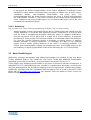
2.1.2.1 Overview of the Architecture
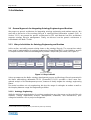
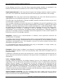
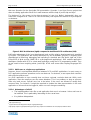
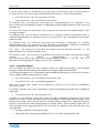
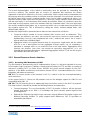
The proposed architecture as shown in Figure 2: Abstract Architecture is organized in layers
according to the control- and data flow (the control flow is indicated by the arrows) as well as the
degree of abstraction of the constituent components. The former means that components at a
higher layer invoke and request data from components at the lower layers. The latter means that
components at the same abstraction level can be found on the same architecture layer. A single
operation of components at a higher level of abstraction can trigger several low level operations.
For example, a functionality provided by an ontology-based application front-end may invoke some
D6.9.1 Specification of NeOn architecture and API V2
Page 11 of 49
ontology runtime services, each of them, in turn, making use of several ontology infrastructure
services. These services rely on requests to specific data sources, which are accessed via
connectors of the data abstraction layer.
ONTOLOGY ENGINEERING
ONTOLOGY RUNTIME
ONTOLOGY-BASED APPLICATIONS’ FRONT-END
ONTOLOGY- ENGINEERING TOOLS’ FRONT-END
Ontology
Editor
Ontology
Browser
Semantic
Portal
...
ONTOLOGY ENGINEERING SERVICES
...
ONTOLOGY USAGE SERVICES
Use Case
Modeling
Browsing/
Visualization
Debugging
Language
Translation
StructuredModel
Transformation
Inconsistency
Resolution
Ontology
Learning
Collaborative
Editing
Functional
Evaluation
Ontology
Mapping
Ontology
Modularization
Performance
Evaluation
RA / DEVELOPMENT / INTEGRATION
Semantic
Search
Form
Retrieval
Related
Services
Reasoning
Related
Services
Other
Ontology
Services
Automatic
Ontology
Population
Cleansing
Fusion
TESTING / EVALUATION
CORE ONTOLOGY SERVICES
ONTOLOGY INFRASTRUCTURE SERVICES
Querying
Reasoning
Repository
Registry
Datasource Abstraction
connector
DBMS
connector
Filesystem
connector
connector
External Ontology Repository
connector
Semantic
Web
Service
Registry
connector
Remote Ontologies
onto
onto
Figure 2: Abstract Architecture
Note that many of the concepts employed for this architecture proposal, i.e. the presentation
components, platform services, data source abstraction and connectors follow J2EE and SOA best
practices. Also, the organization in (three different) layers is inspired from the n-tier architecture – a
well-known organization principle in software engineering. We now briefly discuss these concepts
2006–2008 © Copyright lies with the respective authors and their institutions.
Page 12 of 49
NeOn Integrated Project EU-IST-027595
and the components at the different layers (see [Singh2002, McKenzie2006] for more information
on J2EE and SOA best practices).
The Data Layer: This layer hosts any kind of datasources, including databases and file systems.
This may also encompass ontological sources such as external ontologies hosted in repositories,
semantic web services hosted in registries and any ontology on the web that can be retrieved via
its URI.
Note that services external to the system can be regarded as a component of the data layer
because their processing is transparent to the internal components. The processing can be
considered a black-box that simply provides data for internal components:
The Logic Layer: At this layer, there are application-specific services that are implemented for a
particular use case and operate on specific object models. The former encapsulate the processing
logic and the latter capture the data. These services invoke ontology lifecycle services to manage
and retrieve semantic data. Accordingly, object models may encapsulate data coming from
conventional datasources like databases (data) or from ontological sources (semantic data), or
both. In any case, the actual data comes from a persistent storage, most often a database. The
data source abstraction can be used to hide specific datasource implementations by providing a
uniform API and specific connectors.
While not shown in Figure 2: Abstract Architecture, services at the logic layer run on a specific
platform, which provides orthogonal functionalities for the management, configuration, and
identification (registry) of services as well as access control and security.
The Presentation Layer: This layer hosts presentation components that the user interacts with.
These components could be simply pages or interactive forms of a web-based system or more
sophisticated Uis of a desktop application that contains a variety of widgets. The engineering and
runtime operations performed by the user on these components translate to calls to services
situated at the logic layer. The data returned by these services is then presented by the
components together with the static content.
We will now continue with a more detailed elaboration on ontology-related services.
2.1.2.2 Ontology Services
Ontology services are organized in one layer for ontology infrastructure services and one layer for
the higher level ontology lifecycle services. While the control and data flow of lifecycle and core
services are top-down as shown in Figure 2: Abstract Architecture, the interaction between the
different lifecycle activities typically corresponds to the structure of the corresponding lifecycle
activities, e.g. they follow a sequential flow. However, the actual interaction depends on the needs
of a particular use case. That is, ontology lifecycle services can be invoked and controlled by
application-specific services as needed.
Ontology Services: Functionalities offered by services at these layers are used by lifecycle
services. An ontology registry service is used to find and publish ontologies. An ontology repository
service provides access, manipulation and storage (persistence is supported by the lower level
datastore) at the level of ontologies and at the level of ontology elements. That is, repository
functionalities are also available for axioms, concepts, properties, individuals etc. The repository
service also includes logging and versioning to ensure reversibility. Besides the common repository
retrieval methods, a query service offers a generic mechanism for retrieval.
D6.9.1 Specification of NeOn architecture and API V2
Page 13 of 49
Finally, an inference service is available for standard reasoning tasks such as consistency
checking, classification etc.
Ontology Engineering Services: The architecture contains services for the requirement analysis
that has functionalities similar to the ones supported in an IDE for software development, e.g. for
requirements elicitation, modelling of use cases and specification of reasoning and retrieval tasks
involved in the use cases.
In the actual development, services are provided for ontology browsing, visualization, editing and
integration. In particular, browsing and visualization supporting ontologies as well as nonontological artefacts such as interface signatures, data base schema, and UML models to help in
identifying reusable artefacts. To enable reuse, there are services for the translation of existing
ontologies to the target representation formalism. Services for (semi)-automatic transformation of
non-ontological sources to ontologies are also incorporated into the architecture to facilitate reuse.
This transformation is possible in both directions to ensure the interoperability of ontology data
w.r.t. these data sources. Services for ontology learning are also provided to accelerate the
development process by the generation of a base version that can be further refined.
Implementations of specific interaction protocols enable a collaborative editing process. The
mapping service includes support for the identification and specification of ontology modules as
well as their relations and dependencies. Also, it includes the specification of concept mappings
required for the alignment of ontologies.
After the base ontologies have been further developed, adapted to requirements and integrated,
they have to be tested and evaluated. For these tasks, there are services for debugging
(identification of axioms that are responsible for or affected by the inconsistency) and for the
inconsistency resolution of the conflicts [Haase2007]. Also, there are services that evaluate the
coverage of the ontology w.r.t. the representative set of retrieval and reasoning tasks envisaged for
the use cases (functional evaluation).
Finally, performance evaluation services are essential to meet the requirements and are
incorporated into the architecture. In order to meet performance targets for particular scenarios,
different configurations for ontology axiomatization may be considered.
Ontology Runtime Services: In Figure 2: Abstract Architecture some application-specific services
are shown to illustrate that ontologies may be used as a technology to implement use cases of a
particular OIS. This can involve reasoning, retrieval, but also other tasks enabled by ontologies. In
order to support these ontology-based services, the architecture contains the following runtime
services that are rather independent from specific use cases.
Services that can automatically populate the KB reduce the effort needed for the manual creation
of instance data. These services are performed by agents that request external ontology data as
well knowledge extractors that crawl external non-ontological sources. They implement learning
algorithms to extract instances from text and multimedia contents. Some of these population
services (and ontology learning services) may incorporate procedures for natural language
processing [Valarakos2004] as subcomponents.
Finally, the quality of the acquired instance data has to be ensured. Cleansing services are
available to adapt the format and labels to the application requirements. The same instances
extracted from different sources may have different labels. Knowledge fusion services identify and
resolve such occurrences. Similarly, knowledge acquired from different sources may be redundant
and often contradictory. This is also addressed by the fusion services. These services may
implement a semi-automatic process, which involves the user and engineering services such as
debugging and editing. The arrows in Figure 2: Abstract Architecture illustrate this interaction
between runtime and engineering services. This interaction is supported by the evolution support,
a feature part of these runtime services.
2006–2008 © Copyright lies with the respective authors and their institutions.
Page 14 of 49
NeOn Integrated Project EU-IST-027595
2.1.2.3 Designing OIS with the Generic Architecture
We now discuss how this architecture can act as a reference that can be adapted to match
functional and technological requirements of a particular ontology-based information system.
Matching Functional Requirements: The presented architecture is very generic and targets the
management of the entire ontology lifecycle. Implementing the whole architecture would result in a
fully-fledged integrated system that supports both the engineering and the application of
ontologies. However, a particular application often requires only a subset of the envisaged
services.
Applications may feature only engineering, or only usage of ontologies that already have been
engineered using another system. Then only engineering and runtime services, respectively, have
to be incorporated into the concrete architecture of the final application. In general, the functional
requirements of the system have to be analyzed. Then these requirements have to be mapped to
services of the architecture. Finally, for each of the identified services, more fine-grained
functionalities have to be derived w.r.t. the use cases to be supported by the application.
For instance, an application that only uses RDF(S) ontologies may not need any lifecycle services
at all. Imagine a web application, which simply presents FOAF profiles manually imported from
external sources. Then only core ontology services are needed to import, store and retrieve
information from the profiles. A more sophisticated version may employ agents to crawl profiles
from the web. Even then, only population and basic cleansing is needed, because due to the use
of RDF(S), no inconsistencies can arise that would require engineering services. Now, imagine an
application using OWL ontologies to manage resources of a digital library. Resources are
annotated with ontology concepts that can be defined by the user. Most annotations are extracted
automatically and even new concept descriptions are suggested by the system to capture the
knowledge contained in new library resources. Clearly, this application would need a wide range of
runtime and engineering services and hence, an integrated application with lifecycle support.
Matching Technological Requirements: The presented architecture is of abstract nature and
free of assumptions about specific technological settings. For the development of a specific
application, it can be used as a reference to identify the components (as discussed previously) and
to organize them with the suggested abstraction layers and control-flow. Then, given specific
technological constraints, a concrete architecture paradigm can be chosen and applied to the
abstract architecture.
These paradigms capture best practices in different application settings and can also give
additional guidance for OIS engineering. We will now outline standard paradigms in software
engineering and discuss for which exemplary settings they are most appropriate.
Architecture paradigms can be distinguished along three dimensions, namely the degree of
distribution, coupling and granularity of components. Distribution can range from non-distributed
rich client, over client-server, three-tier, multi-tier to fully-distributed P2P architectures. The last two
dimensions make up the differences of two more concrete architecture paradigms with specific
platform assumptions, namely the component-oriented multi-tier J2EE architecture [Singh2002]
and the Service-oriented Architecture (SOA) [McKenzie2006]. While J2EE comprises of tightlycoupled and relatively fine-grained components, SOA advocate the use of loosely-coupled and
coarse-grained services.
The main idea behind multi-tier architectures is the encapsulation of each tier, meaning any tier
can be upgraded or replaced without affecting the other tiers. While this organization principle has
been adopted (where layer stands for tier), the proposed architecture does not make any
assumptions about how components may be distributed. In fact, the layered organization can be
seen as an orthogonal principle that can be combined with any of the mentioned paradigms.
D6.9.1 Specification of NeOn architecture and API V2
Page 15 of 49
For instance, elements of the architecture can be implemented as components of a desktop
application, e.g. the backend maps to a file system, services and control-flow map to Plain Old
Java Objects (POJOs) and their call hierarchy and GUI components map to Swing widgets. In
another use case, more flexible access may be required, the application logic may call for more
processing capabilities, and the amount of data cannot be managed efficiently by a file system.
Then, a database can be employed as backend, data access can be provided by Data Access
Objects (DAO) and lifecycle services are realized as Enterprise Java Beans (EJB) of a J2EE
platform, and front-ends are implemented as Java Server Pages (JSP) to deliver contents over the
web.
In some cases lifecycle components could be tightly integrated with other internal systems via
J2EE connectors [Sharma2001]. In other cases external parties may want to choose from different
offerings and therefore demand a more flexible way to discover ontology services at runtime and to
interact with them on the basis of a standardized protocol. Here, SOA may be the choice: The finegrained functionalities of some lifecycle components are encapsulated in form of coarse-grained
services exposed to consumers via WSDL and SOAP. Instead of using a completely new SOA
platform, one may go a more evolutionary way advocated by major J2EE vendors, i.e. switch to a
Service Component Architecture (SCA) that implements SOA. SCA provide guidelines for
decoupling service implementation and service assembly from the details of underlying
infrastructure capabilities. Components can then offer their functionalities as services that can also
be consumed externally. However for internal consumption, they do not necessarily have to be
loosely coupled---since tight coupling can avoid the overhead of creating, parsing and transporting
messages over the network.
In all, the generic architecture gives guidelines for the identification and organization of
components. The examples above illustrate that there are many other aspects that have to be
considered given concrete requirements. After the choice for a concrete platform and the paradigm
to be applied on the architecture, guidance can then be found in the respective reference
architectures, e.g. see [Sharma2001] for J2EE, for SOA and SCA.
2.2
NeOn Toolkit for Ontology Engineering
In this section we provide an overview of the NeOn toolkit core components that represent an
implementation of the NeOn reference architecture to support the ontology engineering phase.
Thus, its components can be roughly separated into
•
front end (GUI),
•
ontology engineering services, and
•
ontology infrastructure services.
Additionally, Eclipse components play an essential role in the architecture. They provide the basis
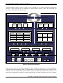
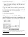
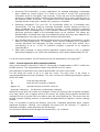
for different functionalities on all three layers of the architecture. In the following figure we assign
the main plug-ins from the basic NeOn Toolkit to the three layers of the architecture.
2006–2008 © Copyright lies with the respective authors and their institutions.
Page 16 of 49
NeOn Integrated Project EU-IST-027595
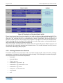
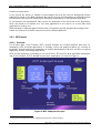
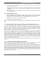
Figure 3: The plug-ins of the basic NeOn toolkit
These three layers have been introduced in the NeOn architecture [WaterfeldWeiten2007]. The
figure presented above provides a refinement of the ontology engineering (or “design time”)
aspects of the ontology lifecycle by instantiating the abstract components with actual plug-ins of
the NeOn toolkit core. Not all core plug-ins are shown in the figure to not blur the overall picture.
Plug-ins dealing with the branding of the toolkit, with the online help system, or that provide generic
utility functionality or third party libraries are left out.
In the next section we will provide some details about the functionality of the different plug-ins and
also describe the important dependencies between them. This should illustrate how they can be
reused when developing other plug-ins.
2.2.1 Ontology Infrastructure Services
The built-in infrastructure components of the core NeOn Toolkit provide services for basic ontology
management, storage and querying/reasoning functionality. The following list contains all plug-ins
that implement these infrastructure capabilities:
•
datamodel
•
datamodelBase
•
flogic-parser
•
ontobroker-ng_kernel-g3
•
ontobroker-ng_ontobroker-core
•
ontobroker-ng_server
•
ontoprise-licensechecker
•
touchgraph
•
util
D6.9.1 Specification of NeOn architecture and API V2
Page 17 of 49
These plug-ins support both Flogic and OWL-DL and subsume the datamodel and reasoner
components. The ontology management aspects for both language use a common API. Since the
two languages differ in many respects, of course, the objects that are passed through this API are
very different. Nevertheless, the basic infrastructure and access methods are shared between both
languages. For query answering and reasoning two inference engines are contained in the set of
infrastructure components. For processing Flogic models and queries we exploit OntoBroker
[Ontobroke 2007b]. For reasoning about OWL-DL models and processing SPARQL queries we
exploit the KAON-2 disjunctive datalog engine [Motik 2006].
Currently the functionality of the mentioned plug-ins is made accessible by the engineering level
plug-ins, mainly com.ontoprise.ontostudio.flogic2 for access to Flogic models and
com.ontoprise.ontostudio.owl3 for accessing OWL models.
As described in the NeOn Registry and Repository deliverable [WaterfeldPalma2007] the NeOn
Registry and Repository infrastructure services are defined as web services. There are currently
two realisations of those services with different characteristics. It is planned to offer on top of these
web services a common Java API, which will be provided as a NeOn toolkit plug-in.
2.2.2 Ontology Engineering Services
On the level of ontology engineering services we can distinguish between
•
plug-ins providing general functionality like search, writing and reading models, or
refactoring,
•
plug-ins providing support for managing OWL ontologies, and
•
plug-ins providing support for managing Flogic ontologies.
Com.ontoprise.ontostudio.io:
Provides functionality to importing and exporting ontologies in different formats from and to
the local file system or a WebDAV server (Web-based Distributed Authoring and
Versioning).
Com.ontoprise.ontostudio.search:
This plug-in provides some search functionalities for ontological entities like concepts,
attributes, relations and instances.
Com.ontoprise.ontostudio.refactor:
This plug-in provides extension points and associated Java interfaces and classes to
extend the refactoring functionality of the toolkit. This is based on the Eclipse refactoring
framework and supports things like renaming entities, or moving a class/concept from one
place in the taxonomy to another.
Com.ontoprise.ontostudio.owl:
This plug-in is intended to simplify access to OWL models for all NeOn Toolkit plug-ins,
esp. plug-ins developed by NeOn partners or external developers. It simplifies certain
aspects of the underlying Kaon-2 API but also reuses some of the classes and interfaces
defined in Kaon-2. This plug-in is not yet implemented. Currently its functionality is part of
the OWL GUI plug-in because the GUI level support for modelling OWL ontologies is workin-progress.
2
Currently this plug-in is still named com.ontoprise.ontostudio.datamodel, which is slightly too general.
3
Currently this plug-in is still merged with the OWL gui plug-in.
2006–2008 © Copyright lies with the respective authors and their institutions.
Page 18 of 49
NeOn Integrated Project EU-IST-027595
Com.ontoprise.ontostudio.flogic:
This plug-in represents the Flogic modelling capabilities of the NeOn Toolkit. It provides
abstractions to the underlying internal datamodel and thus makes it easier for other plug-ins
to the knowledge representation aspect of the application. It provides access to the
underlying datamodel via an API. The datamodel is realized by OntoBroker’s storage
functionality.
2.2.3 GUI Level Components
The last group of plug-ins from the basic configuration of the NeOn Toolkit consists of GUI level
plug-ins that provide very different functionalities. Some of them are self-contained and only rely on
the plug-ins on the lower levels, others spread over multiple plug-ins.
Com.ontoprise.ontostudio.gui:
This plug-in contains the core UI components like the EntityPropertyView and the ontology
navigator that are shared between Flogic and OWL. Additionally it contains the GUI
features for modelling Flogic ontologies.
Org.ontoprise.ontostudio.owl.gui:
In this plug-in we are currently implementing the functionality to display, navigate and
manipulate OWL-DL ontologies.
Com.ontoprise.ontostudio.ontovisualize:
The ontovisualize plug-in contains a view to graphically visualize Flogic ontologies using the
JpowerGraph library which is customized in the com.ontoprise.jpowergraph plug-in.
The following plug-ins represent framework classes and interfaces to support a common look-andfeel and to enable extensibility and communication means between the components.
Com.ontoprise.ontostudio.swt:
Here, the basic Eclipse SWT (Standard Widget Toolkit) classes are extended and
customized to support the other GUI plug-ins of NeOn Toolkit.
Org.neontoolkit.gui:
In this plug-in the extension points and associated Java interfaces are specified that allow
for extending the NeOn toolkit with additional functionality, in particular to add new nodes
into the ontology navigator and to extend the entity property views for existing and new
entity types.
2.2.4 Other components
Supporting plug-ins which do not nicely fit into the three layer architecture such as “Help” or
“Branding” complete the set of core components of the NeOn Toolkit.
Org.neontoolkit.help:
In this plug-in we define the on-line documentation for the basic features of the NeOn
Toolkit as specified in [NeOn D6.7.1]. The documentation is available via the Help Contents
entry of the Help menu.
Org.neontoolkit.plugin:
This is the branding plug-in. With this plug-in the toolkit can be customized regarding the
splash-screen, the about-dialog etc.
D6.9.1 Specification of NeOn architecture and API V2
Page 19 of 49
2.2.5 Essential Eclipse Plug-ins
Since the NeOn Toolkit is based on the Eclipse framework, which provides a vast variety of
functionalities, we will describe the most important Eclipse plug-ins [Shavor2003] that are used or
extended by the NeOn Toolkit
2.2.5.1 Deployment, Eclipse Framework
org.eclipse.core.resources
This org.eclipse.core.resources plug-in manages the resources in the userworkspace. It provides handles to create, modify and delete all kinds of resources in the
workspace (such as projects, files and folders). The NeOn Toolkit uses theses resources to
manage the content of the ontology navigator component. It has the notion of an ontology
project, which supports specific functionalities like hosting multiple ontology resource.
Org.eclipse.core.runtime
The runtime platform is implemented in the org.eclipse.core.runtime plug-in. It
includes the basic plug-in super-class, plug-in preferences, logging objects, etc. We also
find core utility methods (such as ProgressMonitors, IsafeRunnable, Ipath, etc.) and the
extension registry, which manages the extension points and their extensions, in this plug-in.
All plug-ins in the NeOn Toolkit depend on this plug-in because every plug-in containing an
activator class controlling the plug-in’s lifecycle must have a dependency to the runtime
plug-in.
2.2.5.2 User Interface
org.eclipse.swt
The org.eclipse.swt plug-in contains the classes of the Standard Widget Toolkit (SWT).
This is the graphics toolkit of eclipse containing all basic UI elements, such as trees, tables,
labels, comboboxes, etc. All plug-ins that provide a user interface in the NeOn Toolkit need
to access the SWT classes. For example, the Entity Properties View consists of some
composites (org.eclipse.swt.widgets.Composite) and a tabbed container
(org.eclipse.swt.custom.CtabFolder) containing the different property pages. Every
property page is using several SWT classes to implement the GUI features.
Org.eclipse.jface
Jface is a UI toolkit that helps solving common UI programming tasks. Jface also acts as a
bridge between low-level SWT widgets and your domain objects, e.g. by providing viewers
that implement the MVC (model-view-controller) pattern using
•
content providers which retrieve the domain objects and
•
label providers the determine the representation of the domain objects.
The basic wizard classes are also implemented in the Jface plug-in. The OntologyNavigator
is implemented as a TreeViewer with a content provider and label provider that delegate
their calls to the extensions of the extendableTreeProvider extension point from the
org.neontoolkit.gui plug-in.
org.eclipse.ui.views
This plug-in provides extension-points to extend the basic eclipse views such as content
outline and property pages. The plug-in for textual editing of F-Logic source code is
implementing an outline page to show the entities contained in the ontology for easier
navigation in the (potentially large) text file.
Org.eclipse.ui.workbench
2006–2008 © Copyright lies with the respective authors and their institutions.
Page 20 of 49
NeOn Integrated Project EU-IST-027595
In this plug-in we find the implementation of the Eclipse workbench (including the basic
interfaces for views, editors and perspectives) and many UI utilities, such as basic actions,
commands, dialogs, auto-completion functionalities, and many more. The
OntologyNavigator and the EntityPropertiesView are views in Eclipse and implement
the view interface IviewPart. The actions contained in the context menus implement the
action interfaces IobjectActionDelegate and IviewActionDelegate which are also
contained in the workbench plug-in.
2.2.5.3 Refactoring
org.eclipse.ltk.core.refactoring and org.eclipse.ltk.ui.refactoring
Another example of basic functionality that the NeOn Toolkit inherits and extends from the
Eclipse framework is concerned with refactoring models. Refactoring is a technical term
from the realm of programming languages. Whenever simple (or complex) modifications
must be executed in a lot of places with in a large set of source code files, an automatic
mechanism to ensure proper and consistent updates is of invaluable help for the developer.
For Java this includes renaming classes or methods, or moving classes or methods
between packages or classes respectively. For ontologies this refers to e.g. removing
classes (how to handle existing instances of this class?) or renaming properties. The
Eclipse basic implementation support the refactoring process by providing means to test
preconditions, to display (hypothetical) results of the refactoring etc. (cf. [Frenzel 2006]).
2.3
NeOn Toolkit Plug-ins
While basic ontology management and editing functionalities are provided by the core NeOn
Toolkit, additional plug-ins can extend the core NeOn Toolkit with additional functionalities
supporting specific lifecycle activities, as they have been discussed in Section 2.1.1.
These plug-ins may implement functionalities on all layers of the NeOn reference architecture. In
deliverable D6.10.1 [Haase2008] we have provided a comprehensive description of the plug-ins
that been developed thus far, including a mapping to the ontology lifecycle activities they support.
Additionally, up-to-date and “live” information about the plug-ins can be found in the NeOn Toolkit
plugin wiki at http://www.neon-toolkit.org/. We therefore refer the reader to these sources for
further information.
D6.9.1 Specification of NeOn architecture and API V2
Page 21 of 49
Runtime Infrastructures
In this section we discuss a number of technologies that may be used for developing runtime
applications based on the NeOn platform. We present a range of technologies for different runtime
infrastructures that may match different technological requirements of the intended application.
As an example, the requirements may concern the realization of the client side of the application,
which may need to be realized as a rich client application in one case or as a pure web client
application in another one.
While allowing for different target infrastructures, we intend to provide standard technologies that
enable use and reuse of NeOn components across different platforms.
2.3.1 WTP based
2.3.1.1 Overview
The Eclipse Web Tools Platform (WTP) project extends the Eclipse platform with tools for
developing J2EE and Web applications. It includes source and graphical editors for a variety of
languages, wizards and built-in applications to simplify development, and tools and APIs to support
deploying, running, and testing applications.
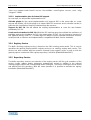
WTP has the dual goals of providing a core set of tools J2EE tools for Web application developers
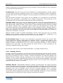
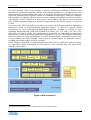
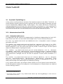
and for tool vendors. WTP is divided into two main subprojects, as shown in Figure 4.
Figure 4: WTP Subproject Scopes4
4
Figure taken from http://www.eclipse.org/webtools/releases/0.7/whatsnew.html
2006–2008 © Copyright lies with the respective authors and their institutions.
Page 22 of 49
NeOn Integrated Project EU-IST-027595
The Web Standard Tools project provides a common infrastructure available to Eclipse-based
development environment targeting multi-tier Web-enabled applications. It includes server tools
which extend the Eclipse platform with servers as first-class execution environments. Server tools
provide an extension point for generic servers to be added to the workspace, and to be configured
and controlled. For example, generic servers may be assigned port numbers, and may be started
and stopped. The WTP extension for Web servers, which builds on the generic server extension
point, includes exemplary adapters for popular commercial and Open Source servers, e.g. Apache
Tomcat.
The scope of the J2EE Standard Tools project is to provide a basic Eclipse plug-in for developing
applications based on standards-based application servers, as well as a generic tooling
infrastructure for other Eclipse-based development products. Included is a range of tools
simplifying development with J2EE APIs including EJB, Servlet, JSP, JCA, JDBC, JTA, JMS, JMX,
JNDI, and Java Web Services. This infrastructure is architected for extensibility for higher-level
development constructs providing architectural separations of concern and technical abstraction
above the level of the J2EE specifications. The J2EE Standard Tools Project builds on the Server
Tools provided by the Web Standard Tools Project to provide support for application servers,
including both servlet engines and EJB containers.
Figure 5 depicts a high level conceptual architecture of WTP. WTP is built from a collection of plugins, organized in layers that depend on each other in a very controlled way: only upper layers
depend on lower layers.
Figure 5: WTP Architecture5
5
Figure taken from http://www.eclipse.org/webtools/releases/0.7/whatsnew.html
D6.9.1 Specification of NeOn architecture and API V2
Page 23 of 49
2.3.1.2 How can NeOn Benefit from WTP?
The WTP focuses on providing infrastructure for application development, in contrast to
infrastructure related to the application run-time. As such, WTP is relevant for NeOn primarily as a
development technology that allows creating NeOn applications for a variety of different target
runtime infrastructures. It is in principle adequate for developing NeOn applications following any of
the target infrastructures following the J2EE architectural model.
Being itself based on Eclipse, WTP as a development platform for NeOn applications integrates
well with components of the NeOn Toolkit as platform for ontology development.
2.3.2 RAP Based Runtime Infrastructure
2.3.2.1 Overview
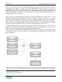
RAP stands for Rich AJAX Platform6. The name should resemble RCP (Rich Client Platform), the
technology that is used to build desktop applications with Eclipse, e.g. the NeOn Toolkit. The goal
of RAP is, to move RCP applications with minimal effort into a web browser. Thus, they can be
used from everywhere over the web without the need of a local installation. A standard web
browser is sufficient. RAP is very similar to Eclipse RCP, but instead of being executed on a
desktop computer RAP applications run on a server and standard browsers are used on the clientside to display the GUI.
One central part of RAP is AJAX (Asynchronous JavaScript and XML). A browser can
communicate with a server via AJAX requests. This allows changing small parts of a web page
without the need to reload it completely. With this ability it is possible to build complete applications
that seem to be executed within a browser. To be precise, this means that the major part of the
application runs on the web server. The data structures are stored, accessed and modified on the
server. Furthermore, the server controls the logic of the user interface on the client. The client has
the look and feel of an application but it displays only the GUI and renders the data it receives from
the server.
2.3.2.2 How can NeOn Benefit from RAP?
In the NeOn context, it is desirable to create AJAX-based web application that can access parts of
the NeOn architecture (e.g. the data model and the ontology) that are hosted on a server. The
NeOn Toolkit is concerned with the creation and modification of ontologies during design-time. At
run-time applications use knowledge bases and ontologies to provide added value. Often, these
applications are not as full-fledged as the NeOn Toolkit and their use cases are likely to be found in
a web context, i.e. users want to access a remote knowledge base via a web interface. Thus, a
seamless integration of web applications with the Eclipse-based NeOn Toolkit implementation or at
least some code-reuse is desirable.
RAP is ideal for this scenario, as the RAP project enables developers to build rich, AJAX-enabled
web applications by using the Eclipse development model, plug-ins with the well known Eclipse
workbench extension points, Jface, and a widget toolkit with SWT API. Developers of a web
application implement the GUI with the Java interface of the SWT (Standard Widget Toolkit) as
they would do for an Eclipse application. In RAP the implementation of SWT is replaced by RWT
6
http://www.eclipse.org/rap/
2006–2008 © Copyright lies with the respective authors and their institutions.
Page 24 of 49
NeOn Integrated Project EU-IST-027595
that uses Qooxdoo for the client-side GUI presentation. Qooxdoo7 is an Open Source project that
aims at creating application-like GUIs in web browsers with the help of JavaScript and Ajax.
The backend, i.e. the access to the data structures in Java (e.g. NeOn’s datamodel), does not
have to be changed at all. There is no need to translate Java objects into streams for Ajax requests
or whatever.
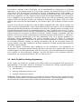
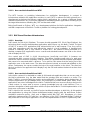
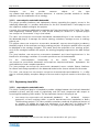
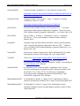
Figure 6. RAP Architecture (right) compared to traditional RCP architecture (left) 8
RAP takes advantage of the Java development tools and the plug-in development tools provided
by Eclipse. The applications are entirely developed in Java as bundles (plug-ins). Everything from
development to launching, debugging and exporting to standard .war files works right out of the
Eclipse IDE (a Web archive (WAR) file is a packaged web application9). RAP enables application
developers familiar with RCP to create web application using the RCP programming model. They
do not need to know anything about JavaScript, HTML and server-side scripting languages like
PHP.
2.3.2.3 Multi-user vs. single-user applications
However, there is one important difference between RCP and RAP applications. In most cases an
RCP application performs operations on its own data set. For instance, a user opens their own files
with exclusive write access.
In a RAP application a user normally does not have a private, exclusive data set. With a web
application, users do usually access the same database. This is no problem, as long as all users
have only read access. Special care has to be taken, if the users are allowed to modify their
common data. For instance, it might be required to update the data representation in the web
application of all users that are logged in, when one user changes something.
2.3.2.4 Advantages of a RAP
• The implementation looks like a real application that runs in a browser. It does not have to
be installed. This is particularly interesting for the casual user.
•
It is platform independent.
7
http://qooxdoo.org/
8
Figure taken from http://www.eclipse.org/rap/about.php
9
http://help.eclipse.org/help32/index.jsp?topic=/org.eclipse.wst.webtools.doc.user/topics/cwwarovr.html
D6.9.1 Specification of NeOn architecture and API V2
Page 25 of 49
•
There are benefits for collaborative work as several users can share the same data basis
that is located on the server.
•
The same Java code base is shared for RCP and RAP applications and the development
is completely in Java. This is a huge benefit for the developers and the code quality of the
application.
•
Most existing NeOn plug-ins can be reused. They only need to be connected to the GUI of
the RAP application.
2.3.2.5 Disadvantages of a RAP
• Nearly every event in the GUI triggers an Ajax call to the server, e.g. opening a (context)
menu. Depending on the speed of the network and the responsiveness of the server the
workflow can be slowed down considerably. This might affect the user’s motivation.
•
Working without an internet connection is impossible.
•
Slow client machines will be overloaded.
However, all of these disadvantages apply to all kinds of web applications. They are not specific for
RAP.
2.3.3 Interoperability of NeOn Engineering Plug-ins and (Ontology) Web Services
As already explained the distinction between development and runtime environment is much
smaller for semantic applications. Thus, due to the existence of Eclipse-based engineering plug-ins
there is a need to have their functionality at runtime. Therefore interoperability between
engineering plug-ins and runtime services is required. The establishing architecture for runtime
services is based on web services according to SOA principles.
OSGI is a core functionality in order to reach this interoperability. The reason is that the Eclipse
runtime itself is completely based on OSGI. OSGI is a light-weight and fully dynamic component
model. It allows running isolated components within a single JVM process. Therefore it is quite
efficient. All Eclipse plug-ins are realized on top of the OSGI component model as bundles.
Although OSGI represents a full fledged component model it is used in Eclipse only within a single
JVM process. There are however several approaches to access OSGI bundles and thus Eclipse
plug-ins also remotely. This forms the basis to realize a larger degree of interoperability with web
services in the following two approaches:
There are two major scenarios where interoperability between NeOn plug-ins and web services is
required.
2.3.3.1 Publish NeOn engineering plugin as Web Service
The first step is to use a NeOn engineering plugin, which has no GUI interactions, as an OSGI
bundle. This bundle is deployed on an OSGI server, which can be accessed remotely.
In order to publish the functionality of the bundle as a web service the interfaces of the bundles has
to be transferred to SOAP request. We use the AXIS2 mechanism to publish ordinary Java
interfaces as web services. Thus in principle arbitrary Java interfaces of the bundle can be chosen.
However usually the exported interface packages for OSGI bundles are the starting point. A
manual step is required, where for the appropriate Java interface adapter classes are generated.
This generation tool (Java2WSDL) is part of the WTP (web tools platform) of Eclipse and thus is
integrated with the NeOn Toolkit.
2006–2008 © Copyright lies with the respective authors and their institutions.
Page 26 of 49
NeOn Integrated Project EU-IST-027595
The generated classes on top of the OSGI bundle will be deployed in an Axis2 server. The Axis2
runtime will run in a servlet container like Tomcat. In order to rely on a common infrastructure the
OSGI server must also run in a servlet container.
2.3.3.2 Loosely coupled engineering plug-ins: NeOn engineering plugin for Web Service
The other side of the interoperability between engineering plug-ins and web services are the
loosely coupled engineering plug-ins. As already explained in the first version of the NeOn
architecture we generate here for existing web services a NeOn engineering plugin.
We use here the same Axis2 infrastructure. In this case however a Java client has to be generated
from the WSDL of the web service. Thus, the WSDL2Java mapping has to be used from WTP.
This time the generated classes are only part of the engineering plug-in at the Eclipse client side.
Thus it is independent of the Axis2 web service runtime. However one usually experience less
subtle compatibility problems if the same infrastructure is used at the server and the client side for
web services.
D6.9.1 Specification of NeOn architecture and API V2
Page 27 of 49
3 NeOn Toolkit API
3.1
Core NeOn Toolkit Plug-ins
In this section we will provide an overview of the important aspects for the NeOn Toolkit API, i.e.
we will introduce relevant extension points, interfaces and classes that plug-in developers will refer
to when implementing additional NeOn Toolkit plug-ins. This section will discuss infrastructure,
ontology engineering, and GUI-level APIs. We use the term “core plug-ins” or “core component” to
indicate that these components represent the basis for all other plug-ins of the NeOn Toolkit. They
are central and provide the core functionality that can be used and extended by others.
3.1.1 Infrastructure Level APIs
3.1.1.1 Datamodel and Reasoner
The datamodel and the reasoner are implemented by OntoBroker implementing the Kaon2 API.
Refer to the Kaon2 API10 for more details and example code. The most relevant classes are
The class org.semanticweb.kaon2.api.KAON2Connection11 encapsulates several ontologies
that import each other.
The interface org.semanticweb.kaon2.api.Ontology represents all axioms of an OWLOntology. It provides numerous means of modifying an ontology, by adding, removing axioms, or
imports statements. It can also persist itself and can provide a reasoner object and also request
objects for different levels of querying the model.
The interface org.semanticweb.kaon2.api.owl.axioms.OWLAxiom and its subclasses
ClassMember, SubClassOf, SubPropertyOf, EquivalentObjectProperty, SameIndividualAs
represent OWL axioms that are the underlying means for modelling in OWL. Axioms can be added
and removed from ontologies and can be used for requests to locate certain information in a
model.
The interface org.semanticweb.kaon2.api.owl.elements.OWLEntity and its subclasses
AnnotationProperty, ObjectProperty, DataProperty, Individual. These
classes are “proxy classes” that provide appropriate methods for manipulating the objects but
always write-through and read-through to the underlying ontology.
OwlClass,
A org.semanticweb.kaon2.api.Request allows retrieval of a set of objects from the KAON2 API.
Kaon2 distinguishes between EntityRequests and AxiomRequests. Request objects are obtained
from the ontology instance.
10
http://kaon2.semanticweb.org
11
This interface will be renamed to org.semanticweb.kaon2.api.OntologyManager to better reflect the
actual semantics of this class.
2006–2008 © Copyright lies with the respective authors and their institutions.
Page 28 of 49
Ontologies
NeOn Integrated Project EU-IST-027595
can
also
provide
reasoner
objects
of
the
type
org.semanticweb.kaon2.api.reasoner.Reasoner. A reasoner provides methods to answer
questions over (the entailments of) an ontology.
3.1.1.2 com.ontoprise.ontostudio.datamodel
This plug-in provides interfaces and implements classes supporting the generic access to the
underlying datamodel, i.e. provides abstractions for the GUI oriented NeOn Toolkit plug-ins and
also organizes multiple ontologies into projects.
Currently, this component additionally instantiates the Flogic functionality of the Toolkit. This Flogic
(and engineering) oriented pieces of code should actually be moved to a separate plug-in
com.ontoprise.ontostudio.flogic (see below).
The class com.ontoprise.ontostudio.datamodel.DatamodelPlugin is the activator class for
the datamodel plug-in. It manages the various ontology containers, manages access to ontology
projects, etc.
The eclipse nature com.ontoprise.ontostudio.datamodel.natures.OntologyProjectNature
identifies projects in the workspace as being ontology projects. All projects marked in this way will
be displayed in the ontology navigator. This nature stores the properties of an ontology project,
such as the ontologies loaded in the project, the ontology language supported or the data storage
used.
The Java interface com.ontoprise.ontostudio.datamodel.api.IontologyContainer is the
interface for all ontology containers. It is used to provide access to the datamodel.
For
the
auto-completion
functionality
of
the
NeOn
Toolkit
com.ontoprise.ontostudio.datamodel.autocomplete.CompletionElement
the
class
implements the
result elements of auto-complete operations.
The Java package com.ontoprise.ontostudio.datamodel.event contains listener interfaces
for rename and change operations in the datamodel and also the classes relevant for the events.
The class com.ontoprise.ontostudio.exception.OntoStudioExceptionHandler is a utility
class to uniformly display exception dialogs to the user and to log these events to the eclipse log
files.
3.1.2 Engineering Level APIs
3.1.2.1 com.ontoprise.ontostudio.owl12
This NeOn Toolkit level plug-in is intended to provide a bridge between the low-level datamodel
provided by Kaon2 and the needs of engineering and GUI level components with respect to
accessing and modifying OWL models. The two important classes in this plug-in are
•
com.ontoprise.ontostudio.owl.datamodel.OWLModel:
An
OwlModel
instance
represents a Kaon2 ontology within a specific Kaon2Connection (equivalent to NeOn
Toolkit ontology project). This class provides convenience methods for getting all classes of
an ontology, for getting the super and subclasses of an OWLClass, for getting the all
annotations associated with an OWLEntity, for adding new axioms to the ontology etc.
12
Currently this functionality is still part of the com.ontoprise.ontostudio.owl.gui plug-in.
D6.9.1 Specification of NeOn architecture and API V2
•
Page 29 of 49
com.ontoprise.ontostudio.owl.datamodel.OWLModelFactory: This class provides
means for creating (and forgetting) OwlModel instances and for retrieving ontology objects
given an ontology project.
3.1.2.2 com.ontoprise.ontostudio.flogic13
This plug-in implements the basic means for creating Flogic models within the NeOn Toolkit. It
mainly provides an API to access the underlying datamodel. The abstract class
com.ontoprise.ontostudio.datamodel.api.Statement represents the main mechanism for
communicating with the underlying datamodel in the Flogic half of the NeOn Toolkit. Each
statement represents a modelling primitive that provides means to create Flogic statements and on
a conceptual level access the statements properties independent of the underlying actual
knowledge representation. The long list of subclasses of Statement includes Concept (to create
and retrieve Flogic concepts from an ontology), DirectInstanceOf (to create and retrieve
instances of a given concept), DirectSubclassOf (for the class hierarchy), or InstanceProperty
to represent attribute values of instances. Statements are created by passing appropriate Term
objects to their constructor. They can be used to modify the model via the ModuleContainer’s
addStatement() and removeStatement() methods, and they are used in events sent to
OntologyListeners.
Some additional utility classes are implemented in this plug-in, e.g. the abstract Java class
com.ontoprise.ontostudio.datamodel.DatamodelControl provides static methods to handle
terms, the basic building block of all Flogic “axioms”.
3.1.2.3 com.ontoprise.ontostudio.io
The IO plug-in provides means to import and export models with the NeOn Toolkit. The central
class for this functionality is Java class com.ontoprise.ontostudio.io.ImportExportControl.
It provides methods to load ontologies into a specified ontology project
String[]
importFileSystem(String
ProgressListener listener)
projectName,
String
physicalUri,
And to serialize a specific ontology in a given format to some location:
void exportFileSystem(String fileFormat, String
moduleId, String physicalUri) throws Exception
To
implement
your
own
import
wizard
you
can
projectName,
String
use
the abstract Java class
com.ontoprise.ontostudio.io.wizard.AbstractImportWizard. As examples for import
wizards
you
can
refer
to
the
implementation
of
com.ontoprise.ontostudio.io.wizard.filesystem.FileSystemImportWizard. For exports
there exists the AbstractExportWizard class.
3.1.3 GUI Level APIs
3.1.3.1 com.ontoprise.ontostudio.gui
The GUI plug-in contains the major components of the user interface of the NeOn Toolkit, such as
the Ontology Navigator and the Entity Properties View. Additionally, some basic classes supporting
the extension of the Ontology Navigator and the definition of property pages to be shown in the
Entity Properties View are contained in this plug-in. The core classes of this plug-in are:
13
The classes described here are currently still located in the com.ontoprise.ontostudio.datamodel plug-in.
2006–2008 © Copyright lies with the respective authors and their institutions.
Page 30 of 49
NeOn Integrated Project EU-IST-027595
The class com.ontoprise.ontostudio.gui.GuiPlugin is the activator class for the GUI plug-in.
It controls the life cycle of this plug-in and manages the extensions of the extension-points
•
org.neontoolkit.gui.entityProperties and
•
org.neontoolkit.gui.extendableTreeProvider.
The abstract class com.ontoprise.ontostudio.gui.LoggingUIPlugin is an extension of the
AbstractUIPlugin provided by Eclipse. It additionally contains logging methods to log errors and
warnings, etc.
The class com.ontoprise.ontostudio.gui.navigator.MtreeView is the implementation of the
Ontology Navigator.
The abstract class com.ontoprise.ontostudio.gui.navigator.DefaultTreeDataProvider is
a default implementation for extensions of the org.neontoolkit.gui.extendableTreeProvider
extension point.
The abstract class com.ontoprise.ontostudio.gui.navigator.TreeElement is a default
implementation of the org.neontoolkit.gui.navigator.ItreeElement interface. For elements
shown in the Ontology Navigator it is recommended to extend this class.
The class com.ontoprise.ontostudio.gui.properties.EntityPropertiesView
implementation of the Entity Properties View.
is
the
The abstract class com.ontoprise.ontostudio.gui.properties.BasicEntityPropertyPage
contains
a
default
implementation
of
the
org.neontoolkit.gui.properties.IentityPropertyPage interface. It can be used as a
template for property pages for entities having a URI as identifier.
3.1.3.2 org.neontoolkit.gui
This GUI plug-in provides the basic extension points for adding functionality to the Ontology
Navigator and the Entity Property View of different ontology entities [Erdmann2007].
The Ontology Navigator can be extended to support additional elements in its hierarchical structure
and to support additional drag-and-drop actions.
•
org.neontoolkit.gui.extendableTreeProvider and
•
org.neontoolkit.gui.extendableDropHandler.
Note: New context menu entries can be defined by using the org.eclipse.ui.popupMenus
extension-point.
The Entity Properties View can be extended to support the display and modification of additional
entity types.
•
org.neontoolkit.gui.entityProperties.
In addition to the extension points above that have been described in [Erdmann 2007] a new
feature of the NeOn Toolkit exist which makes it possibility to add multiple property pages to the
Entity Property View. In this way the view can separate different aspects of a single entity and new
plug-ins can provide their own property pages to existing entities. Entity Property Pages now can
have sub-pages. Each page extends the entityProperties extension point and now has some
new attributes.
•
id: unique identifier of the property page
•
name: label of the property page displayed in the tab of the entity property view
D6.9.1 Specification of NeOn architecture and API V2
•
Page 31 of 49
subContributorOf subelement with superContributorId and priority attributes: the
superContributorId identifies the Entity Property View that this property page will be
displayed (this id must match the id attribute of another Entity Property Page. The
priority attribute is used to order the different tabs in a sequential order, lower numbers
being moved to the right.
3.1.3.3 com.ontoprise.ontostudio.swt
This plug-in contains some NeOn Toolkit-specific extensions of the SWT classes of Eclipse. If
contains extensions of the field assist classes (used for the auto-complete functionality) and some
other utilities.
The class com.ontoprise.fieldassist.ContentAssistTextCellEditor is an extension of the
TextCellEditor provided by Eclipse, offering an auto-complete popup menu.
The class com.ontoprise.fieldassist.ContentAssistTextField provides a Text widget with
auto-complete functionalities.
3.2
Support for developing NeOn plug-ins
3.2.1 Using the NeOn Metamodel with the EMF, GEF and GMF Frameworks in
Plugin Development
In this section, we illustrate how to make use of the Eclipse EMF and GMF frameworks in plugin
development. As example, we discuss a plug-in called OntoModel, which is based on the NeOn
metamodel and corresponding UML profile to support the graphical development of OWL
ontologies and ontology mappings.
Figure 7: Ontomodel Plugin Architecture
Figure 7: Ontomodel Plugin Architecture shows how OntoModel builds on Eclipse and some of its
available plug-ins: it builds on the Graphical Modeling Framework (GMF14), which in turn builds on
the Graphical Editing Framework (GEF15) and the Eclipse Modeling Framework (EMF16).
14
http://www.eclipse.org/gmf/
2006–2008 © Copyright lies with the respective authors and their institutions.
Page 32 of 49
NeOn Integrated Project EU-IST-027595
EMF is a code generation facility for building applications based on a structured model. It helps to
turn models into efficient, correct, and easily customizable Java code. Out of our Ecore
metamodel, we created a corresponding set of Java classes using the EMF generator. The
generated classes can be edited and the code is unaffected by model changes and regeneration.
Only when the edited code depends on something that changed in the model, that code has to be
adapted to reflect these changes.
EMF consists of two fundamental frameworks: the core framework and EMF.Edit. The core
framework provides basic generation and runtime support to create Java classes for a model,
whereas EMF.Edit extends and builds on the core framework, adding support for generating a
basic working model editor as well as adapter classes that enable viewing and editing of a model.
EMF started out as an implementation of the MOF specification. It can be thought of as a highly
efficient Java implementation of MOF, and its MOF-like metamodel is called Ecore.
The EMF adapter listens for model changes. When an object changes its state, GEF becomes
aware of the change, and performs the appropriate action, such as redrawing a figure due to a
move request. GEF provides the basic graphical functionality for GMF.
GMF is the layer connecting OntoModel with GEF and EMF. It defines and implements many
functionalities of GEF to be used directly in an application and complements the standard EMF
generated editor.
Figure 8: Components and models used during the GMF-based development of OntoModel
15
http://www.eclipse.org/gef/
16
http://www.eclipse.org/modeling/emf/
D6.9.1 Specification of NeOn architecture and API V2
Page 33 of 49
Figure 8: Components and models used during the GMF-based development of OntoModel
illustrate the main components and models used during the GMF-based development of
OntoModel.
The graphical definition model is the core concept of GMF. It contains the information related to the
graphical elements that are used in our ontology models. However, they do not have any direct
connection to our metamodel. The graphical definition model is generated semi-automatically from
our Ecore metamodel. (Note that, although our editor is UML-based, GEF also provides other
graphical elements.)
Similarly, the tooling definition model is generated semi-automatically from the metamodel to
design the palette and other periphery (menus, toolbars, etc).
A goal of GMF is to allow the graphical definition to be reused for several domains. This is
achieved by using a separate mapping model to link the graphical and tooling definitions to the
selected domain metamodel. This semi-automatically generated model is a key model to GMF
development and is used as input to a transformation step producing the generator model.
The generator model generates the OntoModel plug-in which is then refined with dialogs and other
application-specific user interface aspects. The plug-in bridges the graphical notation and the
domain metamodel when a user is working with a diagram, and also provides for the persistence
and synchronization of both. An important aspect of GMF-based application development is that a
service-based approach to EMF and GEF functionality is provided which can be leveraged by nongenerated applications.
3.3
Core Infrastructure Services
3.3.1 Reasoner Interface
For the runtime or ontology-usage time of the ontology lifecycle one main functionality usually is
the possibility to access the knowledge base in terms of queries. The query answering component
of the NeOn Architecture is comprised of the Inference Server based on the OntoBroker reasoner.
Currently the reasoning component built-in the NeOn Toolkit cannot be accessed from other
processes outside of the toolkit or from other remote clients. The NeOn Toolkit represents a singleuser desktop application for managing and modifying ontologies. This use case is drastically
different from hosting a service which provides query functionality to a knowledge base for remote
access by external client applications.
3.3.1.1 Setup
In order to setup such a service we can follow the installation instructions from the OntoBroker
manual [Ontoprise 2007]17. The Inference Server can be started from the command line by using
the start script.
Start-ontobroker [-p <port>] [-ip <ipadress>]
{[-m][<lang>][-fenc <encoding>] <file>|<url>}+
The following list shows the most relevant command line arguments
17
Currently we develop a web-service based API for accessing the reasoning engine which will be released with the
OntoBroker 5.1 release in April 2008. For NeOn partners a project-license for OntoBroker server is available upon
request from ontoprise.
2006–2008 © Copyright lies with the respective authors and their institutions.
Page 34 of 49
NeOn Integrated Project EU-IST-027595
•
-p represents the port number of the server for receiving queries and commands. Different
port numbers can be used to run different Inference Servers on the same machine. If no
value is given the default port 2267 will be used. This port is registered at IANA.
•
-ip allows specifying the IP address of the host where the server is running. This is only
needed if the server has multiple IP addresses. If no value is given <localhost> is the
default value.
•
-m Materialize the rules from the following file. This improves performance but decreases
loading time and increases memory consumption. Materialization of rules means, that rules
are evaluated entirely at loading time and all inferred facts are added to the KB. The rules
can be later excluded from further inferencing processes.
•
<lang> is one of:
o
–flo file contains an Flogic KB (the default)
o
–oxml file contains an Flogic KB encoded in OXML
o
–rdf file contains an RDF(S) ontology
o
–owl file contains an OWL ontology
This option identifies the language of the following file. For the 5.0 version of the Inference
Server it is recommended to use FLO or OXML since OWL and RDF files are transformed
into the Flogic model at loading time, which implies that some information from the original
models will be lost.
•
-fenc By using this parameter it is possible to set the file encoding used to read the files
This is necessary when the file encoding of a concrete file differs from the default of your
operating system. XML-based files typically provide encoding information in the header.
•
-webservice By passing this switch, the Inference Server will be available as a web
service. The WSDL for the service can be located at
http://<host>:<port>/services/ontobroker?wsdl
Where host and port are set appropriately. By default, the web service is started at port
8267. For testing purposes you can use the HTTP-client by opening a browser with the
following address:
http://<host>:<port>/services/
3.3.1.2 Administration Console
The OntoBroker Administration Console is an easy-to-use graphical user interface to configure and
execute the Inference Server as a server and can also be used on the client side for accessing and
testing the server.
D6.9.1 Specification of NeOn architecture and API V2
Page 35 of 49
Figure 9: The configuration tab of the administration console.
In the configuration tab you can add files or folders containing ontologies that represent the
knowledge base. These files must contain facts and rules in one of the input formats. A
combination of different files or folders can be saved and later imported as a configuration with a
short description. By clicking <Add file...> (<Add folder...>) you can select a file (folder), that the
Inference Server should load (when adding a folder all files with the given input format in this folder
are loaded). According to the file extensions [FLO, RDF(S), OXML, OWL, n3, nt], the file’s input
format is determined. The definition of its input format can be changed by double clicking the
file/folder-name. By marking the checkbox of a file/folder the Inference Server will materialize the
contained facts and rules when executed.
After the configuration is complete, you can choose the port-number (standard port is <2267>) the
Inference Server should run on. If there are multiple IP-addresses on your local host, you can
specify, which one to take to be available in the network. For this, enter the IP-address into the
appropriate field. The Inference Server can also be started as a WebService on the given port,
when “Start as WebService” is activated. When “Run silent” is activated there will be no output on
the OntoBroker console. To start the OntoBroker inference serve just click “Run OntoBroker”.
Your configurations can be saved by clicking “Save” or “Save as...”. You can add new
configurations or delete existing ones by clicking on the appropriate buttons. To create a batch-file
OntoBroker can be started with, click the button “Save as batch-file …”.
After starting OntoBroker a command line box will show up. After all files are successfully loaded,
the OntoBroker Administration Tool shows the message “Connected to ...” and a green check mark
in its status bar. The Administration Console checks OntoBroker after 5 seconds if it has start-up.
In the Settings and Advanced Settings tab several advanced options for OntoBroker can be set.
This includes various possibilities to tweak the internal knowledge representation, to enable/disable
logging and tracing or to change Java options. Additionally, an internal database can be chosen, if
available. Furthermore, timeouts for the OntoBroker socket communication and for the
Administration Console trying to connect to OntoBroker on start-up can be set.
2006–2008 © Copyright lies with the respective authors and their institutions.
Page 36 of 49
NeOn Integrated Project EU-IST-027595
Figure 10: The Setting tabs of the Administration console
3.3.1.3 Inference Server Commands
In this section we present the most frequently used commands for communicating with the
Inference Server. For a complete list of available server commands, confer Section 10 of
[Ontoprise 2007a].
add
Adds a fact to the knowledge base
Syntax:
add <F-Logic fact> e.g.: add mike:man@module1.
Return values:
fact(s) added
Side effects: Causes the cache to be cleared.
Busy
Returns the server status.
Syntax:
Busy
Return values:
yes, no
Side effects: None
commands
Returns a list of all available commands in the server
Syntax:
Commands
Return values:
a list of all available commands in the server
Side effects: None
del
Deletes a fact from the knowledge base
D6.9.1 Specification of NeOn architecture and API V2
Page 37 of 49
Syntax:
del <F-Logic fact> e.g.: del mike:man@module2.
Return values:
fact(s) deleted
Side effects: Causes the cache to be cleared.
Isalive
Checks whether the server is up and running
Syntax:
Isalive
Return values:
inference server on port 1234 is up an running…
Side effects: None
kill
Kills the server
Syntax:
Kill
Return values:
inference server killing…
Side effects: None
query
Sends a F-Logic query to the server and receives the answers
Syntax:
query [<temporary facts>] <flogic query>
e.g.: query “FORALL X,Y <- X:Y.”
Return values:
Side effects: None
shutdown
Shutdown without argument causes the OntoBroker to process all
outstanding queries and commands, but no new queries and
commands are accepted anymore.
The variant “shutdown NOW” causes the OntoBroker to drop all
waiting queries and commands and to stop all running queries and
commands immediately in a controlled way. See also the kill
command.
Syntax:
shutdown [NOW]
Return values:
inference server shutting down ...
Side effects: None
3.3.1.4 Client-Side Access
For accessing the inference server from a client application two script files are available. A query is
sent to the server using the command line client:
query [-h <hostname>] [-p <port>] [-l <user>:<pwd>] <query>
2006–2008 © Copyright lies with the respective authors and their institutions.
Page 38 of 49
NeOn Integrated Project EU-IST-027595
For sending commands to the inference server the command line client can be executed using the
following script:
command [-h <hostname>] [-p <port>] [-l <user>:<pwd>] <command>
The optional arguments <hostname> and <port> specify the location of the server on the remote
machine. If no <hostname> is given the localhost will be used. If no port number is given the
standard port 2267 will be used. When login credentials are required they ca be provided in the
optional arguments <user> and <pwd>.
3.3.1.5 Client-Side Java API
From within Java, the access to an existing Inference Server is very similar to the console-based
access described in the section above. The relevant classes are
com.ontoprise.app.AbstractClient
com.ontoprise.app.EmbeddedCommandClient
com.ontoprise.app.EmbeddedQueryClient
The
AbstractClient provides generic functionality inherited by its subclasses, the
EmbeddedCommandClient and the EmbeddedQueryClient. The constructors of the Clients take the
IP-address and the port-number of the Inference Server as arguments. Once the connection is
established, commands can be sent via EmbeddedCommandClient.sendCommand() and queries
can be sent via EmbeddedQueryClient.sendQuery() or queryAllInOne().
sendCommand takes the same arguments as the console command (cf. Section 3.3.1.3 “Inference
Server Commands”) and synchronously returns the Inference Server’s response.
queryAllInOne takes an Flogic query and synchronously returns a two dimensional String array
with bound variables as result of the query.
The sendQuery method asynchronously sends a query to the server and immediately returns. Via
the methods getRowCount and getRow the tuples can be incrementally received from the Inference
Server.
If necessary, both client classes can pass credentials to the Inference Server via the login()
method.
3.3.1.6 Client Functionality of the Administration Console
In addition to the configuration and execution of OntoBroker via the Administration Console it can
also be used to access a remote server acting as a client. In the Communication tab you can
specify the remote machine which hosts the inference server by providing server (host) and the
port. When authorization is required the user and password can be given in the corresponding
fields. When clicking the “Connect” button the connection will be established. If the Administration
Tool was able to connect to the inference server an appropriate message appears in the status
bar.
D6.9.1 Specification of NeOn architecture and API V2
Page 39 of 49
Figure 11: The client-side aspects of the administration console
In the Query section of the administration console you can enter arbitrary F-Logic-queries (cf.
[Ontoprise 2007b]) to be sent to the Inference Server. The magnifier icon sends the query and
initiates the reasoning process. The results for queries will be displayed in the bottom part of the
window. In order to provide additional facts that should be used during reasoning, they can be
entered together with the query in the query field. Each fact must be terminated with a new-line
character (see escaping below). These facts will be added temporarily to the KB for the time of the
reasoning about the given query.
Choosing the »Default Namespace« and the »Default Module« - entry and changing the query will
affect the result view. By activating the options »fill null«, »skip sending answer« and »number of
answer« the processing behaviour of the query can be influenced.
In a similar manner as for sending queries to the Inference Server, commands can be issued. In
the »Command« tab you can send commands and receive the server’s responses. The set of
available commands is briefly discussed in one of the following sections.
Sometimes it is necessary to send special characters to the server. In order to send them
appropriately they must be quoted according to the following table.
\n
Line break after temporary facts.
\“
Marks quotes to be quoted inside of queries or commands.
\\
Marks a backslash inside of queries and commands.
In the Browse tab you can visualize the ontology hosted in the Inference Server. After clicking
“Load Ontology” the taxonomy of the server’s KB is loaded and can be navigated in a convenient
way.
3.3.1.7 Web Service Interface for the Reasoner
The Inference Server web service provides four operations:
1.
“command” – use this operation to send commands to the Inference Server
2006–2008 © Copyright lies with the respective authors and their institutions.
Page 40 of 49
NeOn Integrated Project EU-IST-027595
2. “transaction” – use this operation to add(s and remove multiple facts in a single message
3. “query” – use this operation to send Flogic queries
4.
“queryBatch” – special operation to send multiple queries in a single message
Figure 12: Visualization of WSDL for operations and SOAP bindings of the Inference Server
Please see Figure 8 for an overview of the structure of the Inference Server web server description
(the WSDL document), esp. for the specifications of the operations. For retrieving the actual WSDL
description of the Inference Server open a web browser using this URL with appropriate IP and
port numbers:
http://<host>:<port>/services/ontobroker?wsdl
For the query operations the web service returns a result set following a dynamic XML schema
within the queryResponse element. For bound variables in each result tuple its value is returned in
an XML tag with the same name as the variable. For example the Flogic query
FORALL X,Y <- (X is 1.0 or X is 2.0) and Y is “Hi”.
The web service returns the following XML:
<queryResponse>
<queryKey>238</queryKey>
<result><X>1.0</X><Y>”Hi”</Y></result>
<result><X>2.0</X><Y>”Hi”</Y></result>
</queryResponse>
3.3.2 Extensibility of the Reasoner
The Flogic reasoner OntoBroker can be extended by everybody to support features that are not
easy to implement using pure logic, or which are too costly during query answering time. This
includes e.g. mathematical operations to do calculations with the atomic datatype number,
D6.9.1 Specification of NeOn architecture and API V2
Page 41 of 49
operations on character strings, conversions between different datatypes, handling of calendar
dates, or connecting to external data sources such as databases, full-text indexes, or searchengines (or even other Inference Server instances).
OntoBroker provides a built-in mechanism to introduce procedural attachments into the logic
reasoning process. Since Flogic implements a subset of First-Order Logic and its complete
knowledge representation is based on predicates and (Horn) formulas, procedural attachments
also come in the form of predicates. Each built-in has a name and takes a fixed number of
arguments.
In order to implement your own built-in you simply create a Java class that extends the abstract
class com.ontoprise.operators.SimpleBuiltin. As an example we specify the concat/3 builtin that can concatenate two character strings to create a new one. In the built-in’s constructor we
simply define the name and the arity of the built-in/predicate:
this.predicate = “concat”;
this.arity = 3;
Since this built-in should only be available for concatenating strings, and not, e.g. numbers we can
restrict its signature, i.e. the admissible types of values for its arguments:
possibleSignatures = new int[][] {
{STRING, STRING, VARIABLE},
{STRING, VARIABLE, STRING},
{VARIABLE, STRING, STRING},
{STRING, STRING, STRING}};
This statement says that all argument patterns are admissible that have at least two strings and the
third argument is either a string or a variable. Even built-ins should follow the declarative tradition
of logic programs by allowing all possible flows of information, i.e. they should, if possible, not
assume certain input or output arguments. In our example this means, that a variable at the first
argument position is ok, as long as the second and third arguments are ground strings. The
implementation has to make sure that all specified signatures are correctly handled.
The OntoBroker built-in mechanism provides a number of available types that can be used to
specify the signatures:
•
ANY
e.g. X,f(X),bar,”foo”,-3.1
•
GROUND
e.g. bar,”foo”,-3.1, f(2)
•
NUMBER
e.g. 0, -3.1
•
STRING
e.g. “foo”
•
CONSTANT
e.g. bar, “foo”, -3.1
•
FUNCTION
e.g. f(X,Y)
•
VARIABLE
e.g. X, Y
•
GROUNDFUNCTION
e.g. f(1,3),”http://x”#bar
•
LIST
e.g. [bar, “foo”, 3]
Optionally, each built-in can specify some documentation about its implemented functionality and
about the semantics of its arguments:
this.description = “concatenate two strings”;
this.parameters = “first string, second string, concatenation result”;
2006–2008 © Copyright lies with the respective authors and their institutions.
Page 42 of 49
NeOn Integrated Project EU-IST-027595
The actual implementation of the built-in’s functionality must be provided by overwriting the
receive() method. This method gets an Ituple as argument that represent the (three)
arguments of the built-in. Within the receive() method this Ituple object must be interpreted and
the missing value (the variable position in the tuple) must be computed. Once all values are known
the built-in must call the send() method passing a new Ituple object containing all values. It is
important that this tuple object must be ground, i.e. must not contain variables and it must match
with the input tuple, i.e. the two tuples must formally be unifyable. Often it is possible to reuse the
input tuple and only replace some of its members with the computed values. Also one input tuple
can result in multiple output tuples, e.g. a square root built-in sqrt/2 could return the positive and
the negative square root. This is achieved by calling the send() method multiple times, with
different tuple objects.
Besides the simple built-ins presented above there are two other kinds of built-ins:
•
Connector built-ins enable to access external data sources such as databases. They
subclass the abstract Java class com.ontoprise.operators.Connector and instead of
implementing receive() they implement the eval() method and send a list of Ituple
objects rather than individual tuples.
•
Aggregator built-ins are special because they do not process single tuples but are called
once for a set of input tuples and can aggregate all these tuples, e.g. by computing a
maximum or average value or can create the sum of all input values. Aggregators must
subclass the abstract Java class com.ontoprise.operators.Aggregation. It is not
intended that third-party developers implement aggregation built-ins. Thus we will not give
more details about the API, here.
3.3.3 General Reasoner Service Interface
3.3.3.1 Accessing OWL Reasoners via DIG
The DIG-Interface, developed by the DL Implementation Group, is a de facto standard for access
to Description Logic Reasoners. It utilizes a simple protocol based on HTTP and XML. A number of
reasoners including FaCT++, Pellet, Racer, KAON2 and Jena2 provide support for the DIGInterface. In the NeOn architecture, we therefore foresee DIG as a standard interface for a loose
integration with external reasoners.
DIG 1.1: The current version of the interface is DIG 1.118 (which is also the one implemented by
most reasoners).
In the current version 1.1 there are still problems such as the datatype support for OWL-DL and
compatibility with OWL 1.1.
DIG 2.0: The DIG Working Group is addressing these (and other issues) in the DIG 2.0 proposal.
This new version is intended to provide the following features and extensions:
18
•
Concept language: The core functionality of DIG 2.0 permits a client to tell the reasoner
axioms that make up an OWL 1.1 knowledge and pose semantic queries against that
knowledge base.
•
Extensibility: Different Description Logic reasoners support different Description Logics and
different reasoning facilities. To partly support these differences, DIG 2.0 provides an
extensibility mechanism.
For the complete specification we refer to http://dig.sourceforge.net/
D6.9.1 Specification of NeOn architecture and API V2
Page 43 of 49
•
Accessing Told Information: In many applications (for example debugging a knowledge
base created by several clients) it is useful to be able to access the unprocessed
information sent to a Description Logic reasoner. To this end, one of the standard DIG 2.0
extensions provides the ability to retrieve the information that has been explicitly given to
the reasoner (“told”) as axioms. The simplest form of this extension returns axioms that
explicitly mention at top level a named class, property, or individual.
•
Retracting Information: The core DIG 2.0 functionality builds up a knowledge base
monotonically. The only facility for removing information involves starting over from an
empty knowledge base. A DIG 2.0 extension provides a simple method for retracting
information from a knowledge base. In this retraction extension, only top-level axioms that
had been previously added to the knowledge base can be retracted. The axioms are
identified either via identification tags associated with axioms when they were added to the
knowledge base or by tags associated with retrieved told information.
•
Non Standard Inferences: Non-standard Inferences are increasingly recognised as a useful
means to realise applications. For example, Least Common Subsumer (LCS) provides a
concept description that subsumes all input concepts and is the least specific (w.r.t.
subsumption) to do so. A DIG 2.0 extension provides a proposal for an extension
supporting NSIs.
•
Abox query language: In many practical application systems based on DLs, a powerful
Abox query language is one of the main requirements, which will be addressed by DIG 2.0
For all of the above features, the DIG Working Group has developed a set of proposals19.
3.3.3.2 Current Support for DIG in the NeOn platform
In the current version of the NeOn Toolkit 1.1, we provide an implementation of DIG 1.1 within the
KAON2 reasoner. This implementation allows using KAON2 as a DIG server.
In the following, we describe how to interact with KAON2 in the DIG server mode.
The first thing one needs to do is to start the server. The main class of the server is
org.semanticweb.kaon2.server.ServerMain. The class can take the following parameters relevant
for the DIG mode:
-h
prints the help message
-dig
starts the DIG connector of KAON2
-digport <n>
specifies the port of the DIG connector
-ontologies <directory>
the directory containing the ontologies
Initially the server does not contain any ontologies. Clients use ontology URIs to request ontologies
to be open. When such a request arrives to the server, the registry must somehow translate the
ontology URI into a physical URI to be able to open the actual ontology file. The server does this
through a special ontology resolver. It is possible programmatically to register a custom ontology
resolver.
Then, it is possible to specify the directory (using the –ontologies parameter) which contains
registered ontologies. Similarly, new ontologies are placed into this directory. To register or
unregister ontologies, simply drop them into the directory.
It is possible to start the server through the command line, e.g. as follows:
19
available at http://dig.cs.manchester.ac.uk/overview.html
2006–2008 © Copyright lies with the respective authors and their institutions.
Page 44 of 49
NeOn Integrated Project EU-IST-027595
java org.semanticweb.kaon2.server.ServerMain –ontologies server_root –dig
–digport 8088
3.3.3.3 Implementation plan for future DIG support
As next steps, we will provide implementations for:
GUI-side plugin: As the current implementation only supports DIG on the server side, as a next
step we will provide a GUI-side plugin to to interact with DIG reasoners and to visualize results (in
particular the classification hierarchy) obtained from the reasoner
Support for DIG 2.0: We will extend the existing implementation to cover the new features
provided by DIG 2.0.
A web service interface for DIG 2.0: While the DIG working group has outlined the usefulness of
providing web service interfaces for DIG, the current plans for DIG 2.0 only foresee a transport of
DIG requests directly via HTTP. To better align DIG with the service-oriented architecture of NeOn,
we will provide an interface and implementation compatible with Web Service standards.
3.3.4 Registry Service
The NeOn Ontology registry service is based on the OMV ontology meta model. This is used to
specialize the general purpose ebXML registry service to an ontology registry web service. This
service has been realized with the research oriented Oyster registry server as well as with the
general purpose commercial SOA registry repository CentraSite [WaterfeldPalma2007].
3.3.5 Repository Service
The NeOn repository service is an extension of the registry service. All life cycle operations of the
service (create, update, delete, deprecate, undeprecate) contain in addition to the optional
ontology registry objects the corresponding NeOn ontologies. Thus NeOn ontologies can be stored
and queried from the repository. With the same operation it is possible to maintain the registry
information [WaterfeldPalma2007].
D6.9.1 Specification of NeOn architecture and API V2
Page 45 of 49
4 Conclusion
This second version of the NeOn architecture and API explored two quite different directions.
On one hand it details in many aspects the direction of the first version by describing the ontology
engineering-oriented infrastructure of the NeOn toolkit. In this respect it continues to utilize the rich
functionality of the Eclipse platform and applies it to ontology engineering. A major driving force for
this has been the first experiences from the different case studies and other users of the NeOn
toolkit.
On the other hand it drastically widens the scope of the NeOn architecture by introducing the
technology for the usage of ontology in semantic applications at runtime. The strong separation
between engineering and runtime of traditional applications is blurred to some extent for semantic
applications, because ontologies can be directly evaluated by a reasoner. Nevertheless there is
still a distinction needed for most semantic applications due to completely different application and
load characteristics. We explore several approaches focussing on the usage of web services as
the runtime infrastructure and on utilizing Eclipse-based technology to develop GUI components
for web applications.
The increased usage of the NeOn toolkit also required to have more open interfaces to include
other semantic technology. A prominent example is reasoners. Based on the dual language
approach the NeOn toolkit will be able incorporate both type of reasoners via defined web service
interfaces as an evolution of the DIG interface.
Based on further experiences with the NeOn toolkit in the case studies and from other users we
expect the need for additional open interfaces for important components. Together with further
planned enhancements of the runtime components these will be described in a final deliverable of
the NeOn architecture and API. Opposite to this description this will be a complete and self
contained description.
2006–2008 © Copyright lies with the respective authors and their institutions.
Page 46 of 49
NeOn Integrated Project EU-IST-027595
5 References
Aranda2008
Baldassarre2007
Erdmann2007
C. B. Aranda, J. M. Gomez, G. H. Carcel, C. Baldassare, Y. Wange:
D6.1.2 Report on the user requirements V2, NeOn Project Deliverable
2008
Claudio Baldassarre, Yves Jaques, Alejandro Lopez Perez: NeOn
Deliverable D7.5.1 Software architecture for the ontology-based
Fisheries Stock Depletion Assessment System (FSDAS). August, 2007
Michael Erdmann, Dirk Wenke: D6.6.1 Realisation & early evaluation
of basic NeOn tools in NeOn toolkit V1. NeOn Deliverable, August
2007.
Frenzel2006
L. Frenzel: The Language Toolkit: An API for Automated Refactorings
in Eclipse-based IDEs. Eclipse Magazin Vol. 5, January 2006.
http://www.eclipse.org/articles/Article-LTK/ltk.html
GomezPerez2003
Asuncion Gomez-Perez, Oscar Corcho, Mariano Fernandez-Lopez
Ontological Engineering, Springer, 2003
Haase2007
Peter Haase, Frank van Harmelen, Zhisheng Huang, Heiner
Stuckenschmidt, York Sure: A Framework for Handling Inconsistency
in Changing Ontologies. International Semantic Web Conference
2005:353-367
Haase2008
Peter Haase et al. NeOn Deliverable D6.10.1 Realization of core
engineering components for the NeOn Toolkit. February 2008
McKenzie2006
C. Matthew MacKenzie and Ken Laskey and Francis McCabe and
Peter F. Brown and Rebekah Metz: OASIS Reference Model for
Service Oriented Architecture v1.0, OASIS Official Committee
Specification, approved August 2006
Motik2006
B. Motik: Reasoning in Description Logics using Resolution and
Deductive Databases. PhD Thesis, University of Karlsruhe, Karlsruhe,
Germany, January 2006.
http://web.comlab.ox.ac.uk/oucl/work/boris.motik/publications/motik06
PhD.pdf
D6.9.1 Specification of NeOn architecture and API V2
Ontoprise2007a
Page 47 of 49
Ontoprise GmbH: OntoBroker 5.0. User Manual. October 2007.
http://www.ontoprise.de/content/e799/e893/e938/e954/e956/UserGuid
e_OntoBroker_5.0_ger.pdf
Ontoprise 2007b
Ontoprise GmbH: How to write F – Logic – Programs. Covering
OntoBroker Version 5.x. 2007
http://www.ontoprise.de/documents/tutorial_flogic.pdf
Sharma2001
Rahul Sharma and Beth Stearns and Tony Ng: J2EE ™ Connector
Architecture and Enterprise Application Integration. The Java Series.,
2002, Addison-Wesley Longman Publishing Co., Inc. Boston, MA, USA
Shavor2003
Sherry Shavor, J. D’Anjou, J. Fairbrother, D. Kehn, J. Kellerman,
McCarthy, P.: The Java Developer’s Guide to Eclipse. AddisonWesley, 2003.
Singh2002
Inderjeet Singh and Beth Stearns and Mark Johnson and {Enterprise
Team : Designing Enterprise Applications with the J2EE ™ Platform.
The Java Series, 2002. Addison-Wesley Longman Publishing Co., Inc.
Boston, MA, USA
Suarez2007
Mari Carmen Suárez-Figueroa et al.: NeOn Deliverable D5.3.1 NeOn
Development Process and Ontology Life Cycle. August 2007.
Tran2007
Thanh Tran, Peter Haase, Holger Lewen, Óscar Muñoz-García,
Asunción Gómez-Pérez, Rudi Studer: Lifecycle-Support in
Architectures for Ontology-Based Information Systems. Proceedings of
the ISWC/ASWC 2007: 508-522
Valarakos2004
A. Valarakos and G. Paliouras and V. Karkaletsis and G. Vouros:
Enhancing Ontological Knowledge through Ontology Population and
Enrichment. Proc. Of the 14th Int. Conference on Knowledge
Engineering and Knowledge Management (EKAW 2004), LNAI,
volume 3257, pages 144-156, Springer
WaterfeldWeiten2007
W. Waterfeld, M. Weiten, P. Haase: D6.2.1 Specification of NeOn
reference architecture and NeOn APIs, NeOn Project Deliverable 2007
WaterfeldPalma2007
W. Waterfeld, R. Palma, P. Haase: D6.4.1 Realisation & early
evaluation of NeOn service-oriented registry repository, NeOn Project
Deliverable 2007
2006–2008 © Copyright lies with the respective authors and their institutions.
Page 48 of 49
NeOn Integrated Project EU-IST-027595
D6.9.1 Specification of NeOn architecture and API V2
Page 49 of 49
6 Acronyms
FSDAS
DIG
EMF
GEF
GMF
J2EE
OSGI
POJO
RAP
RCP
WSDL
WTP
Fisheries Stock Depletion Assessment System
Ontology based system of FAO in the fishing domain
Description Logic Implementation Group
Known for the Description Logic Reasoner Server Interface
Eclipse Modeling Framework
Utilizing the OMG MOF modelling framework to develop Eclipse
applications
Graphical Editing Framework
Eclipse infrastructure to develop editors together with EMF based
modelling
Graphical Modeling Framework
Integration of GMF and EMF
Java 2 Enterprise Edition.
One of 3 Java platforms. J2EE contains the most advanced features
needed for commercial applications
Open Service Gateway Initiative
Definition of a light-weight component model, used in Eclipse
Plain old Java objects
Java objects realized as conventional Java classes
Rich Ajax Platform
Eclipse platform to develop Ajax based applications with compatibility
to RCP
Rich Client Platform
Utilizing the Eclipse development platform to offer Java runtime
applications
Web Service Description Language.
Major W3C web service standard for describing a web service
Web Tools Platform
Very broad platform of Eclipse for the development of web applications
2006–2008 © Copyright lies with the respective authors and their institutions.