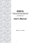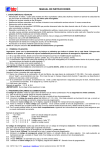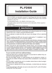
1
MX945GM-D User’s Manual Revision 1.0 http://www.bcmcom.com Rights: Declaration No part of this manual, including but not limited to the products and software described in it, may be reproduced, transmitted, transcribes, stored in a retrieval system, or translated in any form or by any means without the expressed written permission from the manufacturer. Products and corporate names appearing in this manual may or may not be registered trademarks or copyrights of their respective companies and are used only for identification or explanation purposes without intent to infringe. l Pentium M are registered trademarks of Intel Corporation, . l Microsoft and Windows are registered trademarks of Microsoft Corporation. l Phoenix and Award are registered trademarks of Phoenix Technologies LTD.. Responsibility: This manual is provided “As-Is” with no warranties of any kind, either expressed or implied, including, but not limited to the implied warranties or conditions of this product’s fitness for any particular purpose. In no event shall we be liable for any loss of profits, loss of business, loss of data, interruption of business, or indirect, special, incidental, or consequential damages of any kind, even the possibility of such damages arising from any defect or error in this manual or product. We reserve the right to modify and update the user manual without prior notice. WARNING: Replace the system’s CMOS RAM battery only with the identical CR-2032 3V Lithium-Ion coin cell (or equivalent) battery type to avoid risk of personal injury or physical damage to the equipment. Always dispose of used batteries according to the manufacturer’s instructions, or as required by the local ordinance (where applicable). References: This manual is created and written by BCM Technical Dept., but not limited, to the information from the MX945GM-D External Production Specifications, and MX945GM-D Specifications. If any comments, suggestions, or errors on this manual, please write an e-mail to [email protected]. Compliance & Certificate C o m pl i an c e & C e r t i fi c at e ISO 9001 Certificate: This device was produced in our plant with advanced quality system certified by DNV QA Ltd. in according to ISO 9001. This Certificate is valid for: DESIGN & MANUFACTURE OF MOTHERBOARD AND PERSONAL COMPUTERS. CE Declaration: CE marking is a visible declaration by the manufacturer or his authorized representatives that the electrical equipment to which it relates satisfies all the provisions of the 1994 Regulations. FCC Compliance: FCC stands for Federal Communications Commission. This product complies with FCC Rules Part 15 and has been tested, and complied with the EMI rules by a certified body. In normal operation, there shall be no harmful interference caused by this device nor shall this device accept any interference received, including interference that may cause undesired operation of this product. TABLE OF CONTENT MANUAL REVISION INFORMATION 1 ITEM CHECK LIST 1 CHAPTER 1 1-1 1-2 1-3 INTRODUCTION FEATURES OF MX945GM -D SPECIFICATION SYSTEM DIAGRAM 2 2 3 4 CHAPTER 2 2-1 2-2 2-3 2-4 2-5 HARDWARE INSTALLATION HARDWARE INSTALLATION STEPS THE JUMPER/ CONNECTOR LOCATION INSTALL CPU INSTALL DDRII MEMORY MODULE POWER SUPPLY 2-5-1 ATX 20-PIN POWR CONNECTOR: ATX1 2-5-2 ATX 12V POWER CONNECTOR: JPW1 BACK PANEL 2-6-1 MOUSE/KEYBOARD CONNECTOR 2-6-2 VGA PORT 2-6-3 DVI PORT 2-6-4 SERIAL PORTS 2-6-5 USB PORTS 2-6-6 LAN (RJ-45) JACKS 2-6-7 AUDIO PORT CONNECTORS JUMPER AND CONNECTOR 2-7-1 IDE CONNECTOR: IDE1 2-7-2 SERIAL ATAII CONECTORS: SATA1/ SATA2 2-7-3 FAN POEWR CONNECTORS: SYSFAN1/ CPUFAN1 2-7-4 FRONT PANEL CONNECTOR: JFP1 2-7-5 FRONT PANEL AUDIO CONNECTOR: JAUD1 2-7-6 FRONT USB CONNECTORS: F_USB1/F_USB2 2-7-7 FLOPPY DISK DRIVE CONNECTOR: FDD1 2-7-8 CLEAR CMOS JUMPER: CLR_CMOS1 INSTALL PCI CARD 2-8-1 PROCEDURE FOR PCI CARD INSTLLATION 2-8-2 STANDARD INTERRUPT ASSIGNMENTS 2-8-3 PCI INTERRUPT REQUEST ROUTING STARTING UP THE SYSTEM 5 5 6 7 8 9 9 9 10 10 10 10 10 10 11 11 12 12 12 13 13 14 14 15 15 16 16 16 17 18 INTRODUCING BIOS ENTERING SETUP GETTING HELP THE MAIN MENU STANDARD CMOS FEATURES ADVANCED BIOS FEATURES ADVANCED CHIPSET FEATURES INTEGRATED PERIPHERALS 3-7-1 ONBOARD IDE FUNCTION 3-7-2 ONBOARD DEVICE FUNCTION 3-7-3 ONBOARD SUPER IO FUNCTION POWER MANAGEMENT SETUP 19 19 19 20 22 24 26 27 28 29 30 31 2-6 2-7 2-8 2-9 CHAPTER 3 3-1 3-2 3-3 3-4 3-5 3-6 3-7 3-8 3-9 3-10 3-11 3-12 3-13 PNP/PCI CONFIGURATION SETUP PC HEALTH STATUS FREQUENCY/ VOLTAGE CONTROL LOAD FAIL-SAFE/OPTIMIZED DEFAULTS SET SUPERVISOR PASSWORD 33 34 35 35 36 Manual Revision Information Reversion 1.0 Revision History First Release Date Feb. 2007 Item Checklist R MX945GM -D board R MX945GM -D Quick Installation Guide R MX945GM -D User’s Manual on CD (Digital Format) R MX945GM -D Device Drivers on CD R 80 wire ATA66/100 IDE cable x1 R SATA cable x2 R SATA Power cable x2 R CPU Heatsink x1 R I/O Shield for MX945GM -D MX945GM-D 1 Chapter 1 Introduction 1-1 Features of MX945GM-D The MX945GM-D combines the high performance and exceptional value of Intel® 945GM chipset with a full-featured, new generation, industrial board. The Intel® 945GM chipset supports Intel Yonah (Intel® Core TM Duo/ T2000 series, 2M L2 Cache) and Intel Merom(Intel® Core TM 2 Duo mobile/ T5000 & T7000 series, 4M L2 Cache) mobile processor up to 2.33GHz (Napa Platform) in PGA Package with the FSB (Front Side Bus) 533 MHz or 667MHz. The MX945GM-D supports 533/667MHz single-/dual channel DDR2 SDRAM (240pin /1.8V) up to 4GB max. It also provides onboard Intel® 82541PI Ethernet controllers (supports 10/100/1000 Base-TX Ethernet), DMI, CRT video output, Audio Line-Out and 2 COM ports. Furthermore, the MX945GM-D also comes with four USB2.0 ports on back panel and two internal USB2.0 ports headers. This board met today’s market demand of low power consumption, for POS, Kiosk and embedded applications. The 82801GHM I/O Controller Hub (ICH7-MDH) on MX945GM-D contains IDE controllers that supports Ultra ATA mode 66/100. This I/O Controller Hub also supports two SATA ports, one PCI slot, and eight USB ports which support USB 1.1/ 2.0 standard performance, stability and reliability requirements. The MX945GM-D Mini ITX Board is a valuable and it is suitable for all the industry applications, which also well support with the Windows® 2000/ XP and Linux operating systems. MX945GM-D does provide scalability with high reliability & Longevity for Embedded Application. It is a wise choice for today’s computing solution. MX945GM-D 2 1-2 Specification Spec Description Dimension Chipset - Mini ITX form factor PCB size: 6.69”(W) x 6.69”(D) (170 x 170 mm) - Intel 945GM GMCH Chipset - Intel ICH7-MDH (82801GHM) Chipset - Intel Yonah (Intel® CoreTM Duo/ T2000 series) and Intel Merom (Intel® CoreTM 2 Duo mobile/ T5000 & T7000 series) mobile processor up to 2.33GHz (Napa Platform) in PGA Package. - Supports 2MB L2 Cache (Yonah)/ 4MB (Merom) - Supports 533/667MHz FSB (Front Side Bus) - Intel 945GM chipset - Supports video outputs from DVI or VGA output CPU Video Display Memory Socket Expansion Slot Integrate IDE LAN On Board Audio BIOS ROM I/O BIOS Power - Two 240-pin /1.8V DDRII slots - Supports DDRII 533/667 SDRAM (4GB max) - One 32-bit PCI slot - One IDE port by Intel® ICH7-MDH - IDE port supports PIO, Ultra ATA 66/100 modes - Two SATAII ports by Intel® ICH7-MDH - SATAII ports supports data transfer up to 300MB/s - Two Intel 82541PI Gigabit Ethernet LAN - Realtek ALC655 AC’97 audio chip. - Flexible 6-channel audio - 4MB Flash ROM - PS/2 keyboard and PS/2 mouse connectors - Floppy drive connector x1 - Parallel port x1, Serial port x4 (Three on header) - USB 2.0 connector x6, (2 on header) - Audio connector CD-In - Audio connector Line-Out - Award (Phoenix PNP BIOS) - APM /ACPI compliant - ATX standard 20-pin power connector MX945GM-D 3 1-3 System Diagram MX945GM-D Mainboard Diagram MX945GM-D 4 Chapter 2 Hardware installation 2-1 Hardware installation Steps Before starting the system, it is recommended to complete the following steps: 1. Make sure mainrboard jumpers are set in proper position 2. Install CPU 3. Install CPU Heatsink (It is recommended to add proper amount of thermal compound between the CPU Heatsink and CPU) 4. Install System Memory 5. Install Expansion cards (If there is any) 6. Connect IDE and Floppy cables, Front Panel /Back Panel cables 7. Connect ATX Power cables 8. Power-On and Load Optimal settings under BIOS 9. Save the BIOS setting and reboot 10. Install Operating System 11. Install device drivers and Utility MX945GM-D 5 2-2 The Jumper/ Connector Location MX945GM-D 6 2-3 Install CPU 1. The CPU socket comes with a screw to secure to the processor. Turn the screw to “Unlock” position first. 2. Position the CPU above the CPU socket and make sure the gold triangular mark on The corner of CPU is aligned with pin 1 of CPU socket, then insert the CPU to the CPU socket gently. 3. Turn the screw to “Lock” position. Lock Unlock Pin 1 of the socket Gold triangular mark NOTE: Do not force CPU into the socket. It may bend the pins and damage the CPU. WARNING! Be sure there is sufficient air circulation across the processor’s heatsink and Chassis FAN is working correctly. Otherwise, it may cause the processor and mainboard overheat and damage. Install additional auxiliary cooling fan in the system chassis, if necessary. MX945GM-D 7 2-4 Install DDRII Memory Module The MX945GM-D provides two DIMM slots for 240-pins Dual Channel DDRII 533/667 DIMM, which supports the memory size up to 4GB. Since DDRII modules are not interchangeable with DDRI and DDRII standard is not backward compatible, only DDRII memory module is allowed to be installed in DIMM slots (“DIMM1” and “DIMM2”). Otherwise, the system won’t be able to boot up and mainboard might be damaged. 1. There is one notch on the center of DDRII memory module. The module will only fit in the right orientation. 2. Insert the DDRII memory module vertically into the DIMM slot. Then push it in until the gold fingers on memory module is deeply inserted in the DIMM slot. 3. Make sure the plastic clips on both ends of DIMM slot are locked on the DDRII memory module securely. MX945GM-D 8 2-5 POWER SUPPLY The MX945GM-D supports ATX power supply for the power system. Before connecting the power supply connector, always make sure that all components are installed properly in order to avoid damage to the mainboard or components. 2-5-1 ATX 20-Pin Power Connector: ATX1 ATX Power Supply connector is a 20-pins connector comply with Intel ATX standard. The ATX Power Supply allows to use soft power on with a momentary switch that connect from the front panel switch to 2-pins Power On jumper pole on the motherboard. When the power switch on the back of the ATX power supply turned on, the full power will not come into the system board until the front panel power switch is momentarily pressed. Press this power switch again will turn off the power to the system board. 2-5-2 ATX 12V Power Connector: JPW1 This 12V power connector is designed to provide power to theCPU. NOTE: 1. Make sure that all the power connectors (ATX1, JPW1) are connected to proper ATX power supply to ensure stable operation of the mainboard. 2. 130 Watts power supply (and above) is hightly recommended for system stability. 3. ATX 12V power connection should be greater than 6A. MX945GM-D 9 2-6 BACK PANEL The Back Panel Provides the following connectors: 2-6-1 Mouse/ Keyboard Connector: The connector for PS/2® mouse, PS/2® keyboard. 2-6-2 VGA Port: VGA port is the 15-pin D-Subminiature female connector for display monitor. 2-6-3 DVI Port: The DVI (Digital Visual Interface) connector allows connection with an LCD monitor (when there is matched DVI connector on the LCD monitor). It provides a high-speed digital interconnection between the computer and its display device. To connect a LCD monitor, simply plug the DVI connector from LCD monitor into the DVI port (Refer to the LCD monitor user’s manual for detail information). 2-6-4 Serial Ports: This board offers two 9-pins male DIN connectors as serial ports. The ports are 16550A high speed communication ports that send/ receive 16 bytes FIFOs. A serial mouse or other serial devices can be connected to the serial port directly. 2-6-5 USB Ports: The OHCI (Open Host Controller Interface) Universal Serial Bus port is designed for connecting USB devices to the board. MX945GM-D 10 2-6-6 LAN (RJ-45) Jacks: The standard RJ-45 jacks are provided for Local Area Network (LAN) connection. 2-6-7 Audio Port Connectors: The audio connectors are used for audio devices. Line-In (blue audio jack): Or “Side-surround Out” in 5.1 channel mode. Line-In is used for external CD player, or other audio devices. Line-Out (green audio jack): Connector for speakers or headphones. MIC-In (pink audio jack): Or “Center-LEF” in 5.1 channel mode, MIC-In is used for microphones. MX945GM-D 11 2-7 JUMPER & CONNECTOR CONNECTORS 2-7-1 IDE Connector: IDE1 The MX945GM-D has a 32-bit Enhanced PCI IDE and Ultra DMA 66/100 controller that provides PIO modes 0~4, Bus Master, and Ultra DMA 66/100 function. The “IDE1” connector can be connected to IDE devices like IDE HDD & CD-ROM. Signal GND DCS3# DA2 NC NC GND GND GND GND GND NC D15 D14 D13 D12 D11 D10 D9 D8 GND PIN 1 3 5 7 9 11 13 15 17 19 21 13 15 17 19 31 33 35 37 39 2 4 6 8 10 12 14 16 18 20 22 24 26 28 30 32 34 36 38 40 Signal DACT# DCS1# DA0 DA1 IRQ14 DACK# IORDY IOR# IOW# DREQ GND D0 D1 D2 D3 D4 D5 D6 D7 RESET# 2-7-2 Serial ATAII Connectors: SATA1/ SATA2 SATA1/SATA2 are dual high-speed Serial ATAII interface ports. Each supports data transfer rate up to 300MB/s. These two connectors are fully compliant with Serial ATA specification. Each Serial ATA connector can connect to 1 SATA hard drive. MX945GM-D 12 2-7-3 Fan Power Connectors: SYSFAN1/ CPUFAN1 The Fan Power Connectors supports system cooling fan with +12V. It supports 3-pins head connector. When connecting the wire to the connectors. Always take note that the red wire is the positive and should connected to “+12V” pin; the black wire is designated for Ground and should be connected to “GND” pin. WARNING! Be sure there is sufficient air circulation across the processor’s heatsink and Chassis FAN is working correctly. Otherwise, it may cause the processor and mainboard overheat and damage. Install additional auxiliary cooling fan in the system chassis, if necessary. 2-7-4 Front Panel Connector: JFP1 The MX945GM-D provides one front panel connector for the connection to the front panel switches and LEDs. MX945GM-D 13 2-7-5 Front Panel Audio Connector: JAUD1 The JAUD1 front panel audio connector provides connection to the front panel audio. NOTE: If the front audio connector (JAUD1) is not used, pin 5, 6, 9, and 10 have to be jumpered in order to provide signal output to the rear audio ports directly. Otherwise, the Line-Out connector on the back panel will not function. 2-7-6 Front USB Connectors: F_USB1/ F_USB2 The MX945GM-D provides two standard USB 2.0 headers. USB 2.0 technology increases data transfer rate up to a maximum throughput of 480Mbps, which is 40 times faster than the USB1.1, and is ideal for connecting high-speed USB peripherals such as USB HDD, digital cameras, MP3 players, printers, modems. NOTE: Be sure “VCC” and “GND” signals are connected to the right pins in order to avoid possible damage. MX945GM-D 14 2-7-7 Floppy Drive Connector: FDD1 The MX945GM-D provides a standard floppy drive connector that supports 1.44M floppy disk types. JUMPER 2-7-8 Clear CMOS Jumper: CLR_CMOS1 There is a CMOS RAM onboard which as a power supply from external battery to maintain the system configuration data. When it is necessary to clear the system configuration, use Clear CMOS jumper (CLR_CMOS1) to clear data. Follow the instructions below to clear the data: NOTE: The CMOS can be cleared by shorting pin 2-3 at least 30 seconds while the system is OFF. Then return the pin connector back to pin 1-2. Avoid clearing the CMOS while the system is on, this may damage the mainboard. MX945GM-D 15 2-8 Install PCI card The PCI slot supports LAN cards, SCSI cards, USB cards, ad other add-on cards that comply with PCI specifications. At 32bits and 33MHz, it yields a throughput rate of 133MBps. WARNING! Turn off system power when adding or removing PCI card or other component from the system. Failure to do so may cause severe damage to the mainboard and PCI card. 2-8-1 Procedure For PCI Card Installation 1. Read the documentation for the PCI card and make any necessary hardware setting for PCI card such as jumpers. 2. Align the card’s connectors and press it into the PCI slot firmly. 3. Set up the BIOS if necessary. 4. Install the software driver for installed PCI card that is provided by the PCI card manufacturer. 2-8-2 Standard Interrupt Assignments IRQ Priority Standard function 0 N/A System Timer 1 N/A Keyboard Controller 2 N/A Programmable Interrupt 3* 8 Communications Port (COM2) 4* 9 Communications Port (COM1) 5* 6 Onboard Display Controller 6* 11 Floppy Disk Controller 7* 7 Printer Port (LPT1) 8 N/A System CMOS/Real Time Clock 9* 10 ACPI Mode when enabled 10 * 3 IRQ Holder for PCI Steering 11 * 2 IRQ Holder for PCI Steering 12 * 4 PS/2 Compatible Mouse Port 13 N/A Numeric Data Processor 14 * 5 Primary IDE Channel 15 * 1 Secondary IDE Channel * These IRQs are usually available for ISA or PCI devices. MX945GM-D 16 2-8-3 PCI Interrupt Request Routing The IRQ, acronym of interrupt request line, are hardware lines over which devices can send interrupt signals to the microprocessor. The PCI IRQ pins are typically connected to the PCI bus pins as follows: IMPORTANT! If install PCI card on shared PCI slot, make sure that the PCI card driver supports “Shared IRQ” or the card doesn’t need IRQ assignment. Otherwise, conflicts will arise between two PCI groups that will make the system unstable or the PCI card inoperable. MX945GM-D 17 2-9 Starting Up the system 1. After all connection is made, close the computer case cover. 2. Be sure all the switch are off, and check that the power supply input voltage is set to the local voltage, usually the input voltage is 220V∼240V or 110V∼120V which depending on where the country’s voltage used. 3. Connect the power supply cord into the power supply located on the back of system case according to the system user’s manual. 4. Turn on the peripheral as following order: a. The monitor. b. Other external peripheral (Printer, Scanner, External Modem etc… ) c. The system power. For ATX power supplies, user needs to turn on the power supply and press the ATX power switch on the front side of the case. 5. The power LED on the front panel of the system case will light. The LED on the monitor may light up or switch between orange and green after the system is on. If it complies with green standards or if it is has a power standby feature. The system will then run power-on test. While the test is running, the BIOS will alarm beeps or additional message will appear on the screen. If user does not see any thing within 30 seconds from the time power on the system. The system may have failed on power-on test. Recheck the jumper settings and connections or call the retailer for assistance. Beep Meaning One short beep when displaying logo No error during POST Long beeps in an endless loop No DRAM install or detected One long beep followed by three short Video card not found or video card memory bad beeps 6. High frequency beeps when system is CPU overheated working System running at a lower frequency During power-on, press <Del> key to enter BIOS setup. Follow the instructions in BIOS SETUP. 7. Power off the system: User must first exit or shut down the operating system before switch off the power switch. For ATX power supply, user can press ATX power switching after exiting or shutting down the operating system. If user uses Windows 9X, click “Start” button, click “Shut down” and then click “Shut down the computer?” The power supply should turn off after windows shut down. MX945GM-D 18 Chapter 3 Introducing BIOS The BIOS is a program located on a Flash Memory on the motherboard. This program is a bridge between motherboard and the operating system. When user starts the computer, the BIOS program gain control. The BIOS first operates a self-diagnostic test called POST (Power On Self Test) for all the necessary hardware, it detects the entire hardware device and configures the parameters of the hardware synchronization. Only when these tasks are completed done it gives up control of the computer to operating system (OS). Since the BIOS is the only channel for hardware and software to communicate, it is the key factor for system stability, and in ensuring that the system performance as its best. There are several options available in the BIOS Setup main menu (Figure 3-1), which will be explained in the following pages of this chapter. Here are some function keys that may be useful: • Press <Esc> to quit the BIOS Setup. • Press ↑ ↓ ← → (up, down, left, right) to choose, in the main menu, the option user wants to confirm or to modify. • Press <F10> when user has completed the setup of BIOS parameters to save these parameters and to exit the BIOS Setup menu. • Press Page Up/Page Down or +/– keys when user wants to modify the BIOS parameters for the active option. 3-1 Entering Setup Power on the system and by pressing <Del> immediately allows user to enter BIOS Setup menu. If the message disappears before user respond and user still wish to enter Setup, restart the system to try again by turning it OFF then ON or pressing the “RESET” button on the system case. User may also restart by simultaneously pressing <Ctrl>, <Alt> and <Delete> keys. If user does not press the keys at the correct time and the system does not boot, an error message will be displayed and user will be asked to Press <F1> to continue, <Ctrl-Alt-Esc> or <Del> to enter Setup 3-2 Getting Help Main Menu The on-line description of the highlighted setup function is displayed at the bottom of the screen. Status Page Setup Menu/Option Page Setup Menu Press F1 to pop up a small help window that describes the appropriate keys to use and the possible selections for the highlighted item. To exit the Help Window, press <Esc>. MX945GM-D 19 3-3 The Main Menu Once user enter Award BIOS CMOS Setup Utility, the Main Menu (Figure 3-1) will appear on the screen. The Main Menu allows user to select from fourteen setup functions and two exit choices. Use arrow keys to select among the items and press <Enter> to accept or enter the submenu. NOTE: The settings listed in this section are for reference only. Due to the BIOS version difference, some of the settings listed in this manual might be different from the actual BIOS. Phoenix – AwardBIOS CMOS Setup Utility Standard CMOS Features Frequency/Voltage Control Advanced BIOS Features Load Fail-Safe Defaults Advanced Chipset Features Load Optimized Defaults Integrated Peripherals Set Supervisor Password Power Management Setup Set User Password PnP/PCI Configurations Save & Exit Setup PC Health Status Exit Without Saving ? ? ? Esc : Quit ? : Select Item F10 : Save & Exit Setup Time, Date, Hard Disk Type... Figure 3-1 Standard CMOS Features Use this Menu for basic system configurations. Advanced BIOS Features Use this menu to set the Advanced Features available on the system. Advanced Chipset Features Use this menu to change the values in the chipset registers and optimize the system’s performance. Integrated Peripherals Use this menu to specify the settings for integrated peripherals. Power Management Setup Use this menu to specify the settings for power management. MX945GM-D 20 PnP/PCI configurations This entry appears if the system supports PnP/PCI. PC Health Status This entry shows the PC health status. Frequency/Voltage Control Use this menu to specify the settings for frequency clock control. Load Fail-Safe Defaults Use this menu to load the BIOS default values that are factory settings for the stable performance system operation. Load Optimized Defaults Use this menu to load the BIOS default values that are settings for optimal performances system operations. Set Supervisor Password Use this menu to set the Supervisor password. Set User Password Use this menu to set the User password. Save & Exit Setup Save CMOS value changes to CMOS and exit setup. Exit Without Saving Abandon all CMOS value changes and exit setup. MX945GM-D 21 3-4 Standard CMOS Features The items in Standard CMOS Setup Menu are divided into several categories. Each category includes no, one or more than one setup items. Use the arrow keys to highlight the item and then use the <PgUp> or <PgDn> keys to select the value that user wants in each item. Phoenix – AwardBIOS CMOS Setup Utility Standard CMOS Features Date (mm:dd:yy) Tue, Dec, 16 2004 Time (hh:mm:ss) 11 : 26 : 48 ? IDE Primary Master None ? IDE Primary Slave None ? IDE Secondary Master None ? IDE Secondary Slave None Item Help Menu Level > Drive A 1.44M, 3.25 in. Change the day, month, Drive B None year and century Video EGA/VGA Halt On All,But Keyboard Base Memory 640K Extended Memory 56320K Total Memory 57344K ? ? ? ? Move Enter:Select +/-/PU/PD:Value F10:Save ESC:Exit F5:Previous Values F6:Optimized Defaults F1:General Help F7:Standard Defaults Date The date format is <day><month><date><year>. Day Day of the week, from Sun to Sat, determined by BIOS. Read-only. Month The month from Jan. through Dec. Date The date from 1 to 31 can be keyed by numeric function keys. Year The year depends on the year of the BIOS. Time The time format is <hour><minute><second>. MX945GM-D 22 Primary Master/Primary Slave Secondary Master/Secondary Slave Press PgUp/<+> or PgDn/<–> to select Manual, None, Auto type. Note that the specifications of the drive must match with the drive table. The hard disk will not work properly if improper information is entered for this category. If hard disk drive type is not matched or listed, user can use manual option to define the drive type manually. If user selects Manual option, related information is asked to be entered to the following items. Enter the information directly from the keyboard. This information should be provided in the documentation from the hard disk vendor or the system manufacturer. If the controller of HDD interface is SCSI, the selection shall be “None”. If the controller of HDD interface is CD-ROM, the selection shall be “None” Access Mode The settings are Auto Normal, Large, and LBA. Cylinder Number of cylinders Head Number of heads Precomp Write precomp Landing Zone Landing zone Sector Number of sectors MX945GM-D 23 3-5 Advanced BIOS Features Phoenix – AwardBIOS CMOS Setup Utility Advanced BIOS Features ? Hard Disk Boot Priority [Press Enter] Virus Warning [Disabled] CPU L3 Cache [Enabled] First Boot Device [removable] Second Boot Device [CDROM] Third Boot Device [Hard Disk] Boot other Device [Enabled] Swap Floppy Drive [Disabled] Boot Up NumLock Status [On] Security Option [Setup] APIC Mode [Enabled] MPS Version Control for OS [1.4] ? ? ? ? Item Help Menu Level > Move Enter:Select +/-/PU/PD:Value F10:Save ESC:Exit F5:Previous Values F6:Optimized Defaults F1:General Help F7:Standard Defaults Removable Device Priority Press [ENTER] to enter a sub menu which displays every current removable device installed. Use [PageUp] or [PageDown] key to select the first boot removable device. Hard Disk Boot Priority Press [ENTER] to enter a sub menu which displays every current hard drive installed. Use [PageUp] or [PageDown] key to select the first boot hard disk. Virus Warning Allows user to choose the VIRUS Warning feature for IDE Hard Disk boot sector protection. If this function is enabled and someone attempt to write data into this area, BIOS will show a warning message on screen and alarm beep. Disabled (default)No warning message to appear when anything attempts to access the boot sector or hard disk partition table. Enabled Activates automatically when the system boots up causing a warning message to appear when anything attempts to access the boot sector of hard disk partition table. MX945GM-D 24 CPU L3 Cache Level 3 cache is the extra cache built into mainboard between the microprocessor and the main memory. Located away from the CPU, the L3 cache is slower than the L1 & L2 caches. This setting allows user to turn on or off the L3 cache. First/Second/Third/Other Boot Device This option allows user to set the sequence of boot devices where BIOS attempts to load the disk operating system. NOTE: Available settings for “First/Second/Third Boot Device” vary depending on the bootable devices user have installed. Boot Other Device Try to automatically detect any available bootable devices not Enabled in the Boot Device Menu. Boot Up NumLock Status The default value is On. On (default) Keypad is numeric keys. Off Keypad is arrow keys. Security Option This category allows user to limit access to the system and Setup, or just to Setup. System The system will not boot and access to Setup will be denied if the correct password is not entered at the prompt. Setup (default) The system will boot, but access to Setup will be denied if the correct password is not entered prompt. APIC Mode This field is designed to enable or disable the APIC (Advanced Programmable Interrupt Controller). Complied with PC2001 design guide, the system is able to run in APIC mode. Enabling APIC mode will expand available IRQ resources for the system. MPS Version Control For OS This field allows user to select which MPS (Multi-Processor Specification) version to be used for the operating system. User needs to select MPS version. MX945GM-D 25 3-6 Advanced Chipset Features The Advanced Chipset Features Setup option is used to change the values of the chipset registers. These registers control most of the system options in the computer. Phoenix – AwardBIOS CMOS Setup Utility Advanced Chipset Features ** VGA Setting ** On-Chip Frame Buffer Size [8MB] DVMT Mode [DVMT] DVMT/FIXED Memory Size [128MB] Item Help Menu Level > ? ? ? ? Move Enter:Select +/-/PU/PD:Value F10:Save ESC:Exit F5:Previous Values F6:Optimized Defaults F1:General Help F7:Standard Defaults On-Chip Frame Buffer Size Frame Buffer is the video memory that stores data for video display (frame). This field is used to determine the memory size for Frame Buffer. Larger frame buffer size increases video performance. DVMT Mode Use this field to select the mode of the digital monitor used. Available options: [Fixed Mode][DVMT Mode][Both]. DVMT/FIXED Memory Size Specify the size of DVMT memory to allocate for video memory. NOTE: It is not recommended to change these settings unless the user is familiar with the chipset. MX945GM-D 26 3-7 Integrated Peripherals Phoenix – AwardBIOS CMOS Setup Utility Integrated Peripherals ? OnChip IDE Device [Press Enter] ? Onboard Device [Press Enter] ? SuperIO Device [Press Enter] Item Help Menu Level > ? ? ? ? Move Enter:Select +/-/PU/PD:Value F10:Save ESC:Exit F5:Previous Values F6:Optimized Defaults F1:General Help F7:Standard Defaults OnChip IDE Device Please refer to section 3-7-1 Onboard Device Please refer to section 3-7-2 Super IO Device Please refer to section 3-7-3 Onboard LAN Boot ROM This item allows user to invoke the boot ROM of the onboard LAN chip. The settings are: Enable, Disable. Onboard Serial Port 1/2/3/4 Select an address for the serial ports. The settings are: Disabled, 3F8, 2F8, 3E8, 2E8. Serial Port 1/2/3/4 Use IRQ Select an interrupt for the serial ports. The settings are: IRQ3, IRQ4, IRQ5, IRQ7, IRQ9, IRQ10, IRQ11. MX945GM-D 27 3-7-1 OnChip IDE Device Settings Phoenix – AwardBIOS CMOS Setup Utility OnChip IDE Device SATA Mode [IDE] On-Chip Serial ATA [Enhanced Mode] SATA PORT Speed Settings [Disabled] Item Help Menu Level >> ? ? ? ? Move Enter:Select +/-/PU/PD:Value F10:Save ESC:Exit F5:Previous Values F6:Optimized Defaults F1:General Help F7:Standard Defaults SATA Mode Available options: IDE (Default) RAID Selected if user wants to have RAID feature if there are two SATA HDDs. On-Chip Serial ATA This setting is used to specify the SATA Controller. The settings are: Disabled Disable the SATA Controller. Auto PATA and SATA will be arranged by BIOS, and user will be able to see the IDE device status listed under Standard CMOS Features. Combine Mode PATA and SATA will be combined. Max of 2 IDE drives in each channel are available. Enhanced Mode PATA and SATA will both be enabled. Max. of 6 IDE drives are supported. SATA PORT Speed Settings This setting controls the speed of the SATA port. MX945GM-D 28 3-7-2 Onboard Device Phoenix – AwardBIOS CMOS Setup Utility OnChip IDE Device USB Controller [Enable] USB 2.0 Controller [Enable] USB Keyboard Support [Disabled] AC97 Audio [Auto] Onboard LAN Device 1 [Onboard/AGP] Onboard LAN Device 2 [Enabled] Onboard Lan 1 Boot ROM [Enabled] Onboard Lan 2 Boot ROM [Enabled] ? ? ? ? Item Help Menu Level >> Move Enter:Select +/-/PU/PD:Value F10:Save ESC:Exit F5:Previous Values F6:Optimized Defaults F1:General Help F7:Standard Defaults USB Controller This item allows user to enable/ disable the onboard USB controller. USB 2.0 Controller This item allows user to enable/ disable USB 2.0 function. USB Keyboard support This item allows user to enable/ disable legacy USB Keyboard function. Available options are Enabled and Disabled AC97 Audio This item allows user to Enable/ disable the chipset family to support AC97 audio. Available options are Auto and Disabled. Onboard LAN Device 1/2 This setting controls the onboard LAN1 and LAN2 devices. Onboard LAN 1/2 Boot ROM These items enable or disable the initialization of the onboard LAN Boot ROMs during bootup. Select [Disabled] will increase the boot process. MX945GM-D 29 3-7-3 Super IO Device Phoenix – AwardBIOS CMOS Setup Utility Super IO Device Onboard FDC Controller [Enabled] Onboard Serial Port 1 [3F8/IRQ4] Onboard Serial Port 2 [2F8/IRQ3] Item Help Menu Level >> ? ? ? ? Move Enter:Select +/-/PU/PD:Value F10:Save ESC:Exit F5:Previous Values F6:Optimized Defaults F1:General Help F7:Standard Defaults Onboard FDC Controller This item allows user to enable/ disable onboard floppy disk controller function. Available options are Enabled and Disabled Onboard Serial Port 1/2 These items specify the base I/O port addresses of the onboard Serial Port 1 and Serial Port 2. It has the following option: Disabled 3F8/IRQ4 2F8/IRQ3 3E8/IRQ4 2E8/IRQ3 MX945GM-D 30 3-8 Power Management Setup The Power Management Setup allows user to configure the system to most effectively save energy saving while operating in a manner consistent with user’s own style of computer use. CMOS Setup Utility – Copyright(C) 1984-2002 Award Software Power Management Setup ACPI Function [Enable] Soft-Off by PWR-BTTN [Instant-Off] USB KB WakeUP From S3(S4) [Enabled] Resume by Alarm [Disable] PWRON After PWR-FAIL [OFF] ? ? ? ? Item Help Menu Level > Move Enter:Select +/-/PU/PD:Value F10:Save ESC:Exit F5:Previous Values F6:Optimized Defaults F1:General Help F7:Standard Defaults ACPI Function This feature specifies the power saving modes for ACPI function. If the operating system supports ACPI, such as Windows 98SE, Windows 2000, and Windows XP, the user can choose to enter the Standby mode in S1 (POS) or S3 (STR) through the setting of this field. The available options are: S1/POS This item allows user to Enabled/Disabled the Advanced Configuration and Power Management (ACPI). Available settings are Enabled and Disabled. S3/STR The S3 sleep mode is a lower power state where the information of system configuration and open applications/files is saved to main memory that remains powered while most of other hardware components turn off to save energy. The information stored in memory will be used to restore the system when a “wake up” event occurs. Soft-Off by PWR-BTTN When enabled, turning the system off with the on/off button places the system in a very lowpower-usage state, with only enough circuitry receiving power to detect power button activity or MX945GM-D 31 USB KB WakeUp From S3(S4) When setting to enabled, this setting allows the system to be awadkened from S3 state through USB KB. Resume by Alarm When enabled, user can set the date and time at which the RTC (real-time clock) alarm awakens the system from suspend mode. PWRON After PWR-fail This item specifies whether the system will reboot after a power failure or interrupt occurs. Available options are: Off Leaves the system in the power off state. On Leaves the system in the power on state. Former-sts Restore the system to the status before power failure or interrupt occurred. MX945GM-D 32 3-9 PnP/PCI Configuration Setup Phoenix – AwardBIOS CMOS Setup Utility PnP/PCI Configurations Init Display First [PCI Slot] Item Help Menu Level > ? ? ? ? Move Enter:Select +/-/PU/PD:Value F10:Save ESC:Exit F5:Previous Values F6:Optimized Defaults F1:General Help F7:Standard Defaults Init Display First This setting specifies which VGA device is set as the primary source of graphic. Available options are: PCI Slot The system initializes the PCI graphic card first. Onboard The system initializes the onboard graphic first. MX945GM-D 33 3-10 PC Health Status This section displays the Status of CPU, Fan speed, Warning for overall system status. This is only available if there is a Hardware Monitor onboard. Phoenix – AwardBIOS CMOS Setup Utility PC Health Status Current SYS Temperature 35° C/ 95° F Current CPU Temperature 35° C/ 95° F Shutdown Temperature [Disable] System Fan Speed 0 RPM CPU Fan Speed 0 RPM VCore 1.25 V 12 (V) Menu Level > 3.331 V 1.5 (V) 5.24 V 5 (V) 11.542V -12V - 11.12 V -5V - 5.09 V VBAT(V) 3.23 V 5VSB(V) 5.221 V ? ? ? ? Item Help Move Enter:Select +/-/PU/PD:Value F10:Save ESC:Exit F5:Previous Values F6:Optimized Defaults F1:General Help F7:Standard Defaults Shutdown Temperature This item allows user to set up the CPU shutdown Temperature. The settings are: Disabled, 60°C / 140°F, 65°C / 149°F, 70°C / 158°F and 75°C / 167°F. MX945GM-D 34 3-11 Frequency/Voltage Control This section is for setting CPU Frequency/Voltage Control. Phoenix – AwardBIOS CMOS Setup Uitility Frequency/ Voltage Control Auto Detect PCI CLK [Enabled] Spread Spectrum [Disabled] Item Help Menu Level > ? ? ? ? Move Enter:Select +/-/PU/PD:Value F10:Save ESC:Exit F5:Previous Values F6:Optimized Defaults F1:General Help F7:Standard Defaults Auto Detect PCI Clk This item allows user to enable/disable auto detect PCI Clock. The settings are: Enabled, Disabled. Spread Spectrum This item allows user to set the CPU Host/PCI clock and Spread Spectrum. The settings are: Enabled, Disabled. 3-12 Load Fail-Safe/Optimized Defaults Load Fail-Safe Defaults When press <Enter> on this option, the following confirmation dialog box with a message will be displayed: Load Standard Defaults (Y/N)? N Pressing <Y> loads the BIOS default values for the most stable, minimal-performance system operations. Load Optimized Defaults When press <Enter> on this option, a confirmation dialog box with a message will be displayed as follow: Load Optimized Defaults (Y/N)? N Pressing <Y> loads the default values that are factory settings for optimal performance system operations. MX945GM-D 35 3-13 Set Supervisor Password User can set either supervisor or user password, or both of them. The differences are: Supervisor password: Can enter and have full privilege to change the options of the setup menus. User password: Can only enter but do not have the right to change the options of the setup menus. When password function is selected, the following message will appear at the center of the screen to assist user to create a password. ENTER PASSWORD: Type in the password, up to eight characters in length, and press <Enter>. The password typed now will clear any previously entered password from CMOS memory. User will be asked to confirm the password. Type the password again and press <Enter>. User may also press <Esc> to abort the selection and not enter a password. To disable a password, just press <Enter> when prompted to enter the password. A message will confirm that the password will be disabled. Once the password is disabled, the system will boot and user can enter Setup freely. PASSWORD DISABLED. When a password has been enabled, user will be prompted to enter it every time who try to enter the BIOS Setup. This prevents an unauthorized person from changing any part of the system configuration. Additionally, when a password is enabled, user can also require the BIOS to request a password every time the system is rebooted. This would prevent unauthorized use of the computer. User determines when the password is required within the BIOS Features Setup Menu and its Security option. If the Security option is set to “System”, the password will be required both at boot and at entry to Setup. If set to “Setup”, prompting only occurs when trying to enter Setup. MX945GM-D 36