1
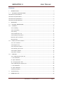
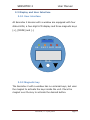
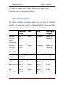
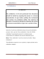
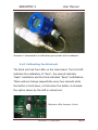
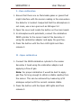
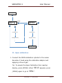
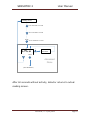
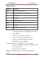
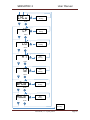
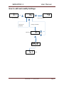
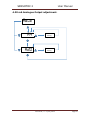
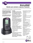
SENSOTOX 2 User Manual READ THE MANUAL BEFORE USING This manual should be carefully read by those who have or will have responsibility for use, maintenance or repair of the product. This product will perform properly only if used, maintained and repaired in accordance with the manufacturer's instructions. CAUTION Disconnect the power before removing the sensor. Remove the cover and the sensor from the unit only if the work area is known not to be dangerous. WARNING Calibration of all new unit should be checked by exposing the sensors to a known gas concentration before putting the instrument into service. For maximum safety, the accuracy of reading of the Sensotox2 should be checked every three months. SENSOTOX 2 User Manual Contents 1. 1.1 INTRODUCTION ....................................................................................................... 2 TECHNICAL SPECIFICATIONS .................................................................................. 4 Sensotox2 EC specifications ............................................................................................. 4 Sensotox2 IR specifications .............................................................................................. 5 Sensotox2 LIE specifications............................................................................................. 6 Sensotox2 PID Specifications............................................................................................ 7 2. OPERATION ............................................................................................................ 8 2.1 PHYSICAL DESCRIPTION ........................................................................................ 9 2.2 Installation ..........................................................................................................10 2.2.1 Installing .......................................................................................................10 2.2.2 Uninstalling ....................................................................................................11 2.2.3 Wiring ...........................................................................................................11 2.2.4 Installing the unit ...........................................................................................12 2.2.5 Earthing instructions .......................................................................................13 External earth connection .........................................................................................13 Internal earth .........................................................................................................13 2.3 Display and User Interface .....................................................................................14 2.3.1 User interface .................................................................................................14 2.3.2 Magnetic key ..................................................................................................14 2.3.3 Using the magnet ...........................................................................................15 2.3.4 Starting up the unit .........................................................................................15 2.3.5 Display readout ..............................................................................................15 2.3.6 Alarm contacts ...............................................................................................16 2.4 Calibration ...........................................................................................................17 2.4.1 Calibrating the blind unit ..................................................................................18 I - Zero calibration ..................................................................................................19 II - Span calibration ................................................................................................19 III - Changing Span value ........................................................................................20 2.4.2 Calibrating the display unit ...............................................................................20 I - Zero calibration ..................................................................................................20 II - Span calibration ................................................................................................22 2.5 Advanced Menu .................................................................................................23 3. Troubleshooting ......................................................................................................29 4. MODBUS/RS-485 ....................................................................................................30 Sensotran, s.l – 31/12/2014 Page 1 SENSOTOX 2 User Manual 1. INTRODUCTION Sensotox 2 EC uses an electrochemical sensor to detect oxygen and toxic gases. It works with voltages from 9 to 36 V dc with an analogue (4-20 mA) or digital (RS-485, ModBus) output. Sensotox2 is equipped with flameproof enclosure, and this may be blind or have a window with a display for reading the gas concentration, status LEDs and magnetic keys for configuration. Sensotox 2 IR uses a non-dispersive infrared sensor to detect combustible gases, carbon dioxide and other gases. It works with voltages from 9 to 36 V dc with an analogue (4-20 mA) or digital (RS-485, ModBus) output. Sensotox2 is equipped with flameproof enclosure, and this may be blind or have a window with a display for reading the gas concentration, status LEDs and magnetic keys for configuration. Sensotox 2 LIE uses a catalytic sensor with high resistance to contaminants for detecting combustible gases (LEL). It works with voltages from 9 to 36 V dc with an analogue (4-20 mA) or digital (RS-485, ModBus) output. Sensotox2 is equipped with flameproof enclosure, and this may be blind or have a window with a display for reading the gas Sensotran, s.l – 31/12/2014 Page 2 SENSOTOX 2 User Manual concentration, status LEDs and magnetic keys for configuration. Sensotox 2 PID uses a sensor to detect volatile organic compounds (VOCs). It works with voltages from 9 to 36 V dc with an analogue (4-20 mA) or digital (RS-485, ModBus) output. Sensotox2 is equipped with flameproof enclosure, and this may be blind or have a window with a display for reading the gas concentration, status LEDs and magnetic keys for configuration. Sensotran, s.l – 31/12/2014 Page 3 SENSOTOX 2 User Manual 1.1 TECHNICAL SPECIFICATIONS Sensotox2 EC specifications Size 190 mm x 150 mm x 140 mm Weight 1.6 kg Sensor Electrochemical Calibration 2 points IP IP-68 Power supply 9-36 V dc, max. 50 mA at 24 V dc Output Display 4 – 20 mA RS-485, at 4.8, 9.6 or 19.2 kB/s 7 segments, 4 digits and 6 LEDs (unit with window) Magnetic key, non-intrusive access for User interface calibration and adjustment (unit with a window). Internal calibration button (blind unit) Temperature -40 a 60 °C Humidity 0-95% RH (non-condensing) Pressure 0.9 – 1.1 Atm Relay contacts* 30 V, 2 A normally open. One for alarm 1 and one for alarm 2. * Consult Sensotran for other possibilities. Sensotran, s.l – 31/12/2014 Page 4 SENSOTOX 2 User Manual Sensotox2 IR specifications Size 190 mm x 150 mm x 140 mm Weight 1.6 kg Sensor Non-dispersive IR Calibration 2 points IP IP-68 Power supply 9-36 V dc, max. 50 mA at 24 V dc Output Display 4 – 20 mA RS-485, at 4.8, 9.6 or 19.2 kB/s 7 segments, 4 digits and 6 LEDs (unit with window) Magnetic key, non-intrusive access for User interface calibration and adjustment (unit with a window). Internal calibration button (blind unit) Temperature -40 a 60 °C Humidity 0-95% RH (non-condensing) Pressure 0.9 – 1.1 Atm Relay contacts* 30 V, 2 A normally open. One for alarm 1 and one for alarm 2. * Consult Sensotran for other possibilities. Sensotran, s.l – 31/12/2014 Page 5 SENSOTOX 2 User Manual Sensotox2 LIE specifications Size 190 mm x 150 mm x 140 mm Weight 1.6 kg Sensor Catalytic Calibration 2 points IP IP-68 Power supply 9-36 V dc, max. 50 mA at 24 V dc Output Display 4 – 20 mA RS-485, at 4.8, 9.6 or 19.2 kB/s 7 segments, 4 digits and 6 LEDs (unit with window) Magnetic key, non-intrusive access for User interface calibration and adjustment (unit with a window). Internal calibration button (blind unit) Temperature -40 a 60 °C Humidity 0-95% RH (non-condensing) Pressure 0.9 – 1.1 Atm Relay contacts* 30 V, 2 A normally open. One for alarm 1 and one for alarm 2. * Consult Sensotran for other possibilities. Sensotran, s.l – 31/12/2014 Page 6 SENSOTOX 2 User Manual Sensotox2 PID Specifications Size 190 mm x 150 mm x 140 mm Weight 1.6 kg Sensor Photoionization Calibration 2 points IP IP-68 Power supply 9-36 V dc, max. 50 mA at 24 V dc Output Display 4 – 20 mA RS-485, at 4.8, 9.6 or 19.2 kB/s 7 segments, 4 digits and 6 LEDs (unit with window) Magnetic key, non-intrusive access for User interface calibration and adjustment (unit with a window). Internal calibration button (blind unit) Temperature -40 a 60 °C Humidity 0-95% RH (non-condensing) Pressure 0.9 – 1.1 Atm Relay contacts* 30 V, 2 A normally open. One for alarm 1 and one for alarm 2. * Consult Sensotran for other possibilities. Sensotran, s.l – 31/12/2014 Page 7 SENSOTOX 2 User Manual 2. OPERATION The calibration of all new instruments acquired from Sensotran should be checked by exposing the sensor to a known concentration of gas before putting the instrument into service. For maximum safety, accuracy should be checked by exposing the sensor to a known concentration of gas over a period of time. Calibration must be checked daily during the initial period of use to ensure that there are no components in the atmosphere which might contaminate the sensor. Check the calibration using a known concentration of gas before use. Recalibrate if the error is excessive. Before shipment, Sensotox 2 instruments are calibrated and checked using Span gas. However, the user should check the operation before first use. Once the unit has been installed, leave it running for 24 hours and check it with gas. Sensotran, s.l – 31/12/2014 Page 8 SENSOTOX 2 User Manual 2.1 PHYSICAL DESCRIPTION The design of Sensotox 2 makes it easy to place and connect at a fixed location to monitor gas. Sensotran, s.l – 31/12/2014 Page 9 SENSOTOX 2 User Manual 2.2 Installation ATTENTION 1. At least 457 mm of armoured cable must be used between group A and B zones. 2. To prevent ignition in explosive atmospheres, the area must be free of flammable gases and the power supply to the detector must be disconnected before opening the cover. 3. For European applications, the installation must meet the requirements of EN 60079-14. 2.2.1 Installing Make 2 holes in the mounting surface 126 mm apart. Sensotran, s.l – 31/12/2014 Page 10 SENSOTOX 2 User Manual 2.2.2 Uninstalling Before dismantling, make sure that power is disconnected. 1. Unscrew the cover by rotating it anti-clockwise. 2. If the unit has a display, remove the four fixing screws and then the ribbon cable connector of the display. 3. Disconnect the power connectors and communication/relay connectors. 4. Disconnect the sensor connector. 5. Unscrew the four studs on the display. 6. Remove the main board. 7. Unscrew the sensor. 2.2.3 Wiring 1. Disconnect the two green connectors. 1 2 3 4 5 6 7 8 Sensotran, s.l – 31/12/2014 Page 11 SENSOTOX 2 User Manual 2. Connect the Sensotox 2 cables via the connection holes. The pins correspond to the following table: Terminal Block 1 Cable Common alarm (*) High/Low Alarm (*) Fault (*) RS485A RS485B Block 2 4-20 mA output Power supply Power supply + (9 a 36 V) (*) Only detectors with a window. Pin# 1 2 3 4 5 6 7 8 2.2.4 Installing the unit 1. Fit the connectors into their respective locations. Save an extra length of cable to allow mounting on the wall. 2. Screw the sensor into the box and place the 4-pin connector (LIE model) or 6-pin connector for other sensors. 3. On units with a window, fit the 16-contact flat cable and separators. 4. On units with a window, pit the display and relay board using four 4 mm screws. 5. Screw the cover on Sensotran, s.l – 31/12/2014 Page 12 SENSOTOX 2 User Manual 2.2.5 Earthing instructions External earth connection Crimp 4 mm2 cable into a 4 mm connector. Internal earth Use the same terminal as for the external earth connection. Sensotran, s.l – 31/12/2014 Page 13 SENSOTOX 2 User Manual 2.3 Display and User Interface 2.3.1 User interface All Sensotox 2 devices with a window are equipped with four status LEDs, a four-digit LCD display and three magnetic keys [+], [MODE] and [-]. ZERO OK SPAN FAULT LOW HIGH + Mode - 2.3.2 Magnetic key The Sensotox 2 with a window has no external keys, but uses the magnet to activate the keys inside the unit. Place the magnet over the key to activate the desired button. Sensotran, s.l – 31/12/2014 Page 14 SENSOTOX 2 User Manual 2.3.3 Using the magnet Briefly touch the magnet onto the MODE circle or the [+] and [-] triangles. Important! Do not drag the magnet, since two functions might be activated. 2.3.4 Starting up the unit Both the detector with a window and the blind one require a start-up time that depends on the built-in sensor. "init" is displayed on the detector with a window, alternating with a countdown. When the count reaches zero, the detector is operative. In both the detector with a window and the blind one, the analogue output current is 2 mA during the start-up time. When the start-up time has elapsed, and provided there is no fault condition, the 4/20 mA analogue output current will be proportional to the sensor reading. 2.3.5 Display readout In the detectors with window, once the detector goes into read mode, it starts an automatic check for possible faults and alarm conditions. If there is no fault or alarm condition, the green "Ok" LED is activated and the gas concentration is shown. Sensotran, s.l – 31/12/2014 Page 15 SENSOTOX 2 User Manual If a fault is shown, the "Faul" LED will lit. Each alarm condition has a corresponding LED. 2.3.6 Alarm contacts The alarm contacts or alarm relays can be used to activate acoustic or luminous alarms. External alarms have normally open contacts which close when there is an alarm. External alarm LED LCD Analogue output Exceeds the low alarm threshold Alarm ALM1 Low Reading Based on reading Exceeds the high alarm threshold Alarm ALM1 High Reading Based on reading Out of range Alarm ALM2 High 8888 22 mA Calibration fault Alarm ALM2 Fault E003 2 mA Sensor drift Alarm ALM2 Fault ADC saturated Fault Alarm ALM2 flashing E004 2 mA flashing E005 2 mA flashing Sensotran, s.l – 31/12/2014 Page 16 SENSOTOX 2 User Manual 2.4 Calibration ATTENTION The calibration of all unit purchased from Sensotran should be tested by exposing the sensor to a known concentration of gas before putting the instrument into service. For maximum safety, the accuracy of Sensotox 2 should be checked by exposing the sensor to a known concentration of gas over a period of time Sensotox 2 units are calibrated using a two point calibration process. First, use the "Zero calibration", then the "SPAN calibration" exposing the sensor to a reference gas concentration to establish the second calibration point. Note: "Zero calibration" must be carried out before "Span Calibration". The calibration requires a zero cylinder, a Span cylinder and a calibration adapter. Sensotran, s.l – 31/12/2014 Page 17 SENSOTOX 2 User Manual Sensotox 2 connected to a calibration gas cylinder with an adapter. 2.4.1 Calibrating the blind unit The blind unit has four LEDs on the main board. The first LED indicates the calibration of "Zero", the second indicates "Span" calibration and the third indicates "Span" modification. These options change sequentially every two seconds while the button is held down, so that when the button is released the option shown by the LED is carried out. Calibration LEDs Sensotox 2 blind. Sensotran, s.l – 31/12/2014 Page 18 SENSOTOX 2 User Manual I - Zero calibration 1. Ensure that there are no flammable gases or gases that might interfere with the sensor reading in the area where the detector is located. Suspected that the atmosphere is not clean, use a zero gas such as Nitrogen 5.0 2. Open the cover and locate the button on the main board. 3. In atmosphere with pollutants, connect the calibration ZERO cylinder to the sensor head of the Sensotox 2 using the calibration adapter and apply the gas flow. 4. Press the button until the Zero LED lights and then release it. II - Span calibration 1. Connect the SPAN calibration cylinder to the sensor Sensotox 2 head using the calibration adapter and applying a flow of gas. Note: For proper calibration it would be best to apply gas flow for long enough to obtain a stable reading from the sensor. This can be achieved by measuring 4/20 analogue output until the current remains stable. 2. Press the button until the Span LED lights and then release it. Sensotran, s.l – 31/12/2014 Page 19 SENSOTOX 2 User Manual III - Changing Span value 1. Press the button until the LED indicating Span modification (Cal. V) lights and then release it. 2. The span value is shown on the LEDs starting sequentially with units, so that first the units are displayed, then the tens and finally the hundreds. 3. Each press of the button increases the Span by one. Once the new value has been set it will be automatically saved if the button is not pressed again 2.4.2 Calibrating the display unit I - Zero calibration 1. Ensure that there are no flammable gases or gases that might interfere with the sensor reading in the area where the detector is located. Suspected that the atmosphere is not clean, use a zero gas such as Nitrogen 5.0 2. To accede to Calibration Menu, Press [MODE] from the actual reading screen. A “2ERO” message appears on the screen. Tip: To pass to Span Calibration, press [MODE]. To return to actual reading press [-]. Sensotran, s.l – 31/12/2014 Page 20 SENSOTOX 2 User Manual 3. In atmosphere with pollutants, connect the calibration ZERO cylinder to the sensor head of the Sensotox 2 using the calibration adapter and apply the gas flow. 4. Press [+] to start calibration. Zero LED will lit and “2ErO” message will be displayed alternatively with a countdown. Tip: Before countdown will finish, you can cancel calibration by pressing any key. 5. When countdown will be completed, LED and “2ERO” disappears and calibration data will be saved. Note: The machine returns to reading the display after 60 seconds of inactivity. When Zero Calibration will be finished, instrument will advance to Span Calibration. Sensotran, s.l – 31/12/2014 Page 21 SENSOTOX 2 User Manual Reading Mode MODE MODE 2ErO - MODE SPAn MODE + + (Countdown) (Countdown) (Display Value) (Display Value) - Reading Mode II - Span calibration 1. Connect the SPAN calibration cylinder to the sensor Sensotox 2 head using the calibration adapter and applying a flow of gas. Tip: To accede the Span Calibration from reading display, press [MODE]. When “2ERO” appears, press [MODE] again to go to “Span”. Sensotran, s.l – 31/12/2014 Page 22 SENSOTOX 2 User Manual 2. Press [+] to start calibration. “Span” LED will lit and “Span” will be displayed alternatively with a countdown. Calibration can be cancelled by pressing any key. 3. When countdown will be completed, LED and “Span” disappears and calibration data will be saved. If the sensor does not have sensitivity enough for being calibrated, “Fail” and “Span” messages will be displayed alternatively; that can suggest than sensor needs to be replaced. 4. To quit the Menu and return to actual reading screen, press [+]. If not, the instrument will return automatically to actual reading screen after a short period. 5. Close the gas valve. 2.5 Advanced Menu Sensotox2 Advanced Menu let you modify several configuration parameters. To enter into Advanced Menu, press the sequence [+], [-] and [MODE]. Display will show then CALu. Ø Pressing [MODE] will move to the next function. Ø Pressing [+] will enter into the setting and show the actual value. Ø Pressing [-] will leave the Advanced Menu. Sensotran, s.l – 31/12/2014 Page 23 SENSOTOX 2 User Manual Reading Screen + Press and hold 1 second - Press and hold 1 second MODE Press and hold 1 second CALu - + Edit Parameter MODE Advanced Menu (Next Parameter) After 60 seconds without activity, detector returns to actual reading screen. Sensotran, s.l – 31/12/2014 Page 24 SENSOTOX 2 User Manual Advanced Menu Display Setting CALu Span Calibration value FC Correction Factor LO Low Alarm HI Hi Alarm Id Instrument ID bAUd Transmission Speed Lite Backlight Aout Analogue output (for LEL & VOC only) (19200, 9600 or 4800) (4 / 20 mA) • To modify a setting, press [MODE] until desired value appears. • Press [+] to enter into the setting. • Press [+] to increase/change the value. • Press [-] to decrease/change the value. • When finished, press [MODE]. If the setting has been modified, new value will blink. • Press [-] or [MODE] to dismiss modifications and go to next setting. • Press [+] to save changes. “SAuE” will be displayed to confirm changes have been stored. Sensotran, s.l – 31/12/2014 Page 25 SENSOTOX 2 User Manual + CALu - MODE + CF - Edit Setting + Edit Setting + Edit Setting MODE Aout - + MODE bAUd - Edit Setting MODE Id - + MODE HI - Edit Setting MODE LO - Edit Setting + Edit Setting MODE Actual Reading Sensotran, s.l – 31/12/2014 Page 26 SENSOTOX 2 User Manual How to edit and modify Settings. 51 + Increased Value - 50 Decreased Value MODE (Setting non modified) 49 (Setting modified) - 51 (Blinking) MODE + SAuE 51 Value Sensotran, s.l – 31/12/2014 Page 27 SENSOTOX 2 User Manual 4-20 mA Analogue Output adjustment. Aout + - A4 + Edit Setting + Edit Setting MODE - A20 MODE Sensotran, s.l – 31/12/2014 Page 28 SENSOTOX 2 User Manual 3. Troubleshooting Error Description and solution E003 Description: Calibration error Solution: Make sure there is gas flow circulation and repeat calibration. If still fails, replace the sensor. E004 Description: Zero Drift Solution: Make sure sensor is in a clean ambient or alternatively, use Nitrogen to do zero calibration. E005 Description: Sensor Over range Solution: Call an Authorized Service Center. E006 Description: Wiring Error Solution: Verify wiring E007 Description: EEPROM Error Solution: Replace main board. Call an Authorized Service Centre. Sensotran, s.l – 31/12/2014 Page 29 SENSOTOX 2 User Manual 4. MODBUS/RS-485 Retrieving gas concentration data from Sensotox 2 through RS-485. The Sensotox 2 communicates by means of MODBUS RTU. All monitors provide 4-byte register value. Note: Gas concentration is the only value that can be retrieved. As example 34 hex = 52 decimal. 1. Communication Setting Transmission MODE:RTU Controller: PC or GasVisor Controller. Baud Rate: 4800, 9600, 19200 bps. Client ID: 1 to 32 2. Message Frame/Communication Procedure Sensotox 2 only support function code 0x03 (read holding registers), which only supports the “Get Reading Value” from the detector. Sensotran, s.l – 31/12/2014 Page 30 SENSOTOX 2 User Manual Requesting Message: Device Function Register Register Quantity Quantity CRC CRC Address Code Address Address of of Low High High Byte Low Byte Registers Registers Byte Byte High Byte Low Byte 00 02 CRC CRC CRC CRC Low High Byte Byte CRC CRC Client ID 03 00 02 Answering Message: Device Function Byte Address Code Count Client ID 03 Register Value 04 Reading Reading Reading Reading byte 4 byte 3 byte 2 byte 1 Note: Detector data length is 4 bytes. Example: Request: 01 03 00 02 00 02 CRC CRC Answer: 01 03 04 00 00 00 3A 7A 20 Note: The maximum distance should be less than 1 Km when using a 1.5 mm2 cable. Sensotran, s.l – 31/12/2014 Page 31 SENSOTOX 2 User Manual sensotran, s.l. Av. Remolar 31 BARCELONA - SPAIN Phone: +34 93 478 5842 Fax: +34 93 478 5592 www.sensotran.com e-mail: [email protected] Sensotran, s.l – 31/12/2014 Page 32