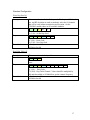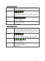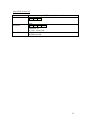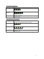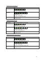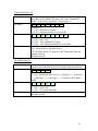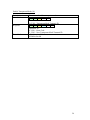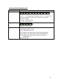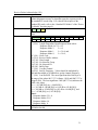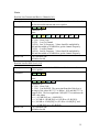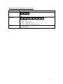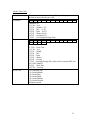
1
PTSS2003 Module and Test Board
User’s Manual
August 2003
Pegasus Technologies, Inc
254 Babbs Road
Lenoir City, TN 37771
(865) 483-7748 (Ph)
(775) 261-0914 (Fx)
[email protected]
IMPORTANT NOTICE
Pegasus Technologies, Incorporated and its subsidiaries (Pegasus) reserve the right to
make changes to their products or to discontinue any product or service without notice,
and advise customers to obtain the latest version of relevant information to verify, before
placing orders, that information being relied on is current and complete. All products are
sold subject to the terms and conditions of sale supplied at the time of order
acknowledgment, including those pertaining to warranty, patent infringement, and
limitation of liability.
Pegasus warrants performance of its products to the specifications applicable at the
time of sale in accordance with Pegasus’s standard warranty. Testing and other quality
control techniques are utilized to the extent Pegasus deems necessary to support this
warranty. Specific testing of all parameters of each device is not necessarily performed,
except those mandated by government requirements.
Customers are responsible for their applications using Pegasus components.
In order to minimize risks associated with the customer’s applications, adequate
design and operating safeguards must be provided by the customer to minimize inherent
or procedural hazards.
Pegasus assumes no liability for applications assistance or customer product design.
Pegasus does not warrant or represent that any license, either express or implied, is
granted under any patent right, copyright, mask work right, or other intellectual property
right of Pegasus covering or relating to any combination, machine, or process in which
such products or services might be or are used. Pegasus’s publication of information
regarding any third party’s products or services does not constitute Pegasus’s approval,
warranty or endorsement thereof.
By using this product, the customer agrees to these terms.
Copyright 2003, Pegasus Technologies, Incorporated
i
Table of Contents
Hardware Overview ........................................................................................................ 1
PTSS2003 Module ...................................................................................................... 1
PTSS2003 Test Board ................................................................................................. 1
Supporting Software........................................................................................................ 2
Networking ..................................................................................................................... 3
Overview .................................................................................................................... 3
Examples .................................................................................................................... 4
RF Communication Requirements................................................................................... 7
Power Up Modes............................................................................................................. 8
Standard PU Modes..................................................................................................... 9
Advanced PU Modes................................................................................................. 10
Range Testing ............................................................................................................... 12
Transparent Mode ......................................................................................................... 14
Serial Communication................................................................................................... 15
Serial Packet Communication.................................................................................... 15
Serial Packet Structure .............................................................................................. 15
Serial Command Groups ........................................................................................... 15
Standard Configuration ............................................................................................. 17
Data .......................................................................................................................... 25
Packet ....................................................................................................................... 26
Status ........................................................................................................................ 32
Custom...................................................................................................................... 36
FCC Information........................................................................................................... 37
iii
Hardware Overview
PTSS2003 Module
The PTSS2003 module is basically a hardware device used for transmitting serial data
over an RF link. It can communicate at several RF and serial baud rates. A block
diagram of the module is shown in Figure 1.
Figure 1: PTSS2003 Module Block Diagram
PTSS2003 Test Board
The PTSS2003 test board provides a mechanism for communicating with the
PTSS2003 module via a standard RS232 link. The test board connects directly to a host
system and has and antenna connector and status LED’s.
1
Supporting Software
Currently, the PTSS2003 is supported through a console application (PTSS2003TR),
which allows access to the majority of the functionality of the PTSS2003 module to be
demonstrated and tested. The console application can be run on Windows 9x machines
and required that the module be connected to a RS232 serial port through the PTSS2003
Test Board or compatible hardware.
2
Networking
Overview
There are several networking options with the PTSS2003 module. Each module has a
configurable network group, ID, and custom code. As implied, the network group can be
used to configure a common group of PTSS2003 modules to communicate amongst
themselves, ignoring messages from other groups. The network ID is the individual
PTSS2003 module’s network address within the group.
There is a specific group and ID that are reserved for group broadcasts. If a network
group of ‘0’ is used in the transmit message, all PTSS2003 modules will listen to the
message, regardless of their group ID. If a broadcast among a specific group is required,
the transmit message should contain the desired group with a network ID of ‘0’.
As additional protection, there is a network custom code. All received packets must
contain the same custom code as code as programmed on the module, regardless if there
is a group broadcasts.
There are 4 main types of transmitted packets: Encoded/Response, Encoded, No
Response, Not Encoded/Response, Not Encoded/No Response. In response messages
(auto reply), the transmitter sends a data packet and waits on a response. For
broadcasting, response messages are not allowed. Similarly, if a module transmits
outside of it’s group, response messages are not allowed as the responding module will
respond within it’s own group.
3
Examples
In the following example, there are 3 different groups. A diagram of the network is
shown in Figure 2.
Figure 2: Network Example
Internal Group Communication
All internal group communication requires that the network group be set to the same
group as the transmitting device. For example, if module G1.A wanted to communicate
with module G1.B, the network group of the transmit packet should be 185 and the
network ID should be set to the corresponding network ID of G1.B. In another example,
if module G1.C wanted to send an internal group broadcast message, the network group
of the transmit packet should be 185 and the network ID should be 0. With the exception
of internal group broadcasts, all internal group communication can auto reply.
4
External Group Communication
It is possible for a group to communicate with a member of another group as long as
the proper network group and ID are used. However, it will not be possible for the
member of that group to auto reply. For example, if module G1.A wanted to
communicate with module G2.B, the network group of the transmit packet should be 200
and the network ID should be set to the corresponding ID of G2.B.
Since the custom code is different, groups 1 and 2 will always ignore messages from
group 3 and vice versa.
5
RF Communication Requirements
In order for a transmitter and receiver to communicate with one another, the
following conditions must be met:
• Same RF baud rate and deviation,
• Same hop table (i.e., same hop table seed),
• Same network custom code,
• Same network group or network group of zero, and
• Rx network ID or network ID of zero.
In order for a transmitter and receive to transmit an auto reply packet, the previous
conditions must be met in addition to the following conditions:
• Transmission must be to a specific network ID within the transmitters network group,
• Transmission network group cannot be zero, and
• Target receiver network ID cannot be zero.
7
Power Up Modes
There are several specialty modes that the PTSS2003 can enter at power up. These
modes are set through the standard power-up (PU) control and parameter (serial
command 12) and the advanced PU control and parameter (serial command 66)
commands.
The standard PU mode contains the following functions:
• Change the serial message response mode,
• Wake or sleep at PU,
• Range Transmit or Receive at PU, and
• Receive at PU.
The advanced PU mode contains the following functions:
• Receive on specific channel at PU,
• Transmit a square wave on a specific channel at PU, and
• Transmit non-modulated data on a specific channel at PU.
In nearly all cases, the advanced PU mode will never be used and may void the FCC
certification if used incorrectly. Therefore, these commands are locked so that they
cannot be accidentally enabled.
8
Standard PU Modes
As mentioned previously, the standard PU modes are enabled through the serial
interface. Most of the standard PU modes are mutually exclusive. For example, the
range test transmit or receive mode cannot operate with the receive at PU mode. As soon
as the serial response is received, the selected power up mode immediately begins
operating.
The standard PU mode serial command data packet contains a 16-bit word.
Specific bits in the standard PU mode word indicate the power up mode.
Table 1: Standard PU Modes
Standard PU Control
7 (LSB)
6
Bit #
15 (MSB)
14
Byte 0
(LSB)
Byte 1
(MSB)
RX
(LSB)
(MSB)
RM2
5 (LSB)
13 (MSB)
4 (LSB)
12 (MSB)
3 (LSB)
11 (MSB)
RM1
RM0
Wake
2 (LSB)
10 (MSB)
1
9
(LSB)
(MSB)
0
8
(LSB)
(MSB)
Range Range Range
RX
TX
AL
Unused Unused Unused Unused Unused Unused Unused TM
Bits
8
7
6-4
Function
Transparent Mode
Receive at PU
Response Mode
3
Wake at PU
2
1
0
Range Rx at PU
Range Tx at PU
Range Activity Level
Description
The module goes into transparent mode after initialization.
The module goes into receive mode after initialization.
Type of serial response when a packet is received. The
following modes are valid:
0b000 RM0 – R0 Packet
(HL+DL+NG+NID+Data+RXPARAM)
0b001 RM1 – R1 Packet (HL+DL+NG+NID+Data)
0b010 RM2 – R2 Packet (HL+DL+NG+NID)
0b011 RM3 – R3 Packet (HL+DL)
0b100 RM4 – R3 Packet (HL+DL)
The module stays awake after initialization at opposed to
going to sleep and having to be awakened.
The module goes into range test receive mode.
The module goes into range test transmit mode.
Activity level of the range indicator.
9
Advanced PU Modes
As mentioned previously, the advanced PU modes are enabled through the serial
interface. All of the advanced PU modes are mutually exclusive.
The advanced PU mode serial command data packet contains two bytes of data. The
first byte is the advanced PU control. The second byte is the advanced PU parameter,
which indicates the channel in the hop table on which to transmit or receive.
Specific bits in the advanced PU mode byte indicate the power up mode.
Table 2: Advanced PU Modes
Advanced PU Control
MSB (Bit 7)
RSV7 Linear Tx
Tx
Rx
Range
NMOD Square on
Hop
Single
Channel
on
on
Table
Freq
Channel Channel
RX
Bits
7
6
Function
Reserved
Linear Hop Table
5
Transmit Non
Modulated Data on
Specified Channel
Transmit Square
Wave Data on
Specified Channel
Receive Data on
Specified Channel
4
3
2
1
0
Range Single
Frequency Rx at PU
Range Single
Frequency Tx at PU
Range Single
Frequency Activity
Level
Range
Single
Freq
TX
LSB (Bit 0)
Range
Single
Freq
AL
Description
Not Used
When enabled, the hop table is initialized with 50
channels evenly spaced from 903 MHz to 927 MHz.
Otherwise, the hop table is generated in the normal
manner.
The module turns on transmitter for the specified channel
after initialization but does not transmit any data.
The module turns on transmitter for the specified channel
after initialization and continuously transmits a square
wave pulse (0b10101010).
The module turns on receiver for the specified channel
after initialization. However, the receive data is not
processed.
The module goes into range test single frequency receive
mode.
The module goes into range test single frequency transmit
mode.
Activity level of the range indicator.
10
Advanced PU Parameter
MSB (Bit 7)
CH7
CH6
CH5
Bits
7-0
Function
Channel
CH4
CH3
CH2
CH1
LSB (Bit 0)
CH0
Description
Specified channel in the hop table on which to transmit or
receive. There are 50 channels in the hop table. If
transmission on the lowest frequency (903 MHz), middle
frequency (915 MHz), or upper frequency (927 MHz) is
desired, the advanced PU parameter should be loaded with
0xFD, 0xFE, and 0xFF, respectively.
11
Range Testing
The PTSS2003 module has built in range test capability. The host system can set up
modules to be a transmitter or receiver and the activity level of the indication LEDs. This
configuration will remain in effect until it is disabled by the host system.
The transmitter will send packets approximately every 300 milliseconds. This message is
broadcast to network group 0, network id 0. Just as in normal operation, the network
custom code should be the same in the transmitter and receiver.
Table 3 shows the PTSS2003 output pins used by the range transmitter test and Table
4 shows the PTSS2003 output pins used by the range transmitter test.
The activity level indicates the active level of the outputs. If the activity level is 1, a
pin will assert a 1 when the indicated condition occurs and default back to 0 at the end of
the condition. If the activity level is 0, a pin will assert a 0 when the indicated condition
occurs and default back to 1 at the end of the condition.
Table 3: Range Test Transmitter Pin Assignments
Range Test Transmitter Pin Assignments
Description
Tx/Rx Line:
Indicates whether the module is configured as a transmitter
or receiver where
0==receiver and 1==transmitter (Activity Level Low) OR
1==receiver and 0==transmitter (Activity Level High)
Packet Transmitted:
Indicates when a packet was transmitted where
0==packet transmitted (Activity Level Low) OR
1==packet transmitted (Activity Level High)
PTSS2003
Module
J1.8
PTSS2003
Test Board
P2.0
J1.7
P2.1
12
Table 4: Range Test Receiver Pin Assignments
Range Test Receiver Pin Assignments
Description
Tx/Rx Line:
Indicates whether the module is configured as a transmitter
or receiver where
0==receiver and 1==transmitter (Activity Level Low) OR
1==receiver and 0==transmitter (Activity Level High)
Packet Received:
Indicates when a packet was received where
0==packet transmitted (Activity Level Low) OR
1==packet transmitted (Activity Level High)
RSSI Range 0 () where
0==RSSI within Range 0 (Activity Level Low) OR
1==RSSI within Range 0 (Activity Level High)
RSSI Range 1 () where
0==RSSI within Range 1 (Activity Level Low) OR
1==RSSI within Range 1 (Activity Level High)
RSSI Range 2 () where
0==RSSI within Range 2 (Activity Level Low) OR
1==RSSI within Range 2 (Activity Level High)
RSSI Range 3 () where
0==RSSI within Range 3 (Activity Level Low) OR
1==RSSI within Range 3 (Activity Level High)
RSSI Not Measured where
0==RSSI not measured (Activity Level Low) OR
1==RSSI not measured (Activity Level High)
PTSS2003
Module
J1.8
PTSS2003
Test Board
P2.0
J1.7
P2.1
J1.6
P2.2
J1.5
P2.3
J1.4
P2.4
J1.3
P2.5
J1.2
P2.6
13
Transparent Mode
The PTSS2003 module has a special mode that allows data written to the serial port
to be automatically loaded and transmitted without the use of loading the buffer and
instructing the module to transmit. This mode, transparent mode, is good in situations
where the user wants to transmit data from a source which is outputting serial data
packets (such as a GPS receiver) and does not want to create a packet, load the buffer,
and send the data. However, there are some downfalls to this mode of operation. The
user will receive no RF status data (such as RSSI). Also, this mode does not transmit
auto reply packets; therefore there is no way of the transmitter knowing if the packet was
received.
In order to exit transparent mode, the ASCII escape sequence of “+++” should be
used. If this escape sequence unsuitable for the application, please contact Pegasus for a
custom firmware package.
The transparent mode module can be setup to transmit packets to a specific module or
all modules within it’s group.
Packets are transmitted based upon a character delay of 10 characters based upon the
baud rate. If no new characters are received or if 80 characters have been written to the
module, the module will automatically transmit the packet. The character delays are
shown in Table 5.
Table 5: Transparent Mode Transmit Delay
Serial Baud Rate
(bits per second)
Bit Time
(seconds)
Byte Time*
(seconds)
1200
0.00083300
2400
0.00041700
4800
0.00020800
9600
0.00010400
19200
0.00005210
38400
0.00002600
57600
0.00001740
115200
0.00000868
* Includes Start and Stop Bits for a Total of 10 Bits
0.0083330
0.0041670
0.0020830
0.0010420
0.0005210
0.0002600
0.0001740
0.0000868
Transmit Delay
(seconds)
0.083333
0.041667
0.020833
0.010417
0.005208
0.002604
0.001736
0.000868
14
Serial Communication
Serial Packet Communication
The serial interface on the PTSS2003 module is relatively simple. The default baud
rate is 38400 with no parity, 8 data bits, and a stop bit. However, the baud rate can be
changed through the serial interface. Since there is no flow control, the only required
serial signals are Rx and Tx. Essentially, the host system sends a command and the
PTSS2003 module processes the command and replies. All commands will receive a
reply to let the host system know that the indicated operation was performed. Figure 3
shows the basic communication flow between the host and the PTSS2003 module.
Figure 3: Host-PTSS2003 Communication
Serial Packet Structure
The serial packets are variable length, where the first two bytes are the length of the
packet (packet length parameter). Many commands are fixed length, and therefore the
length is easy to determine. However, other packets (such as the data packets), are quite
often not the same length. Care should be taken to ensure that the packet length
parameter is the proper value. If the packet length parameter is too small, the entire
received data packet will not be processed. Consequently, if the packet length parameter
is too large, the serial interface will wait until it receives the total number of bytes
indicated by the packet length and the serial interface will appear to hang. The next byte
of the packet is the command ID. In a response message, the following byte is the
command error code.
In situations where the packet parameters are the more than one byte in length, the
parameters should be loaded from LSB to MSB.
Serial Command Groups
There are several commands that the host can send to the module. The commands are
grouped based upon functionality. These groups are shown in Table 6.
15
Table 6: Serial Command Groups
Command Group
Standard
Configuration
Advanced
Configuration
Data
Packet
Status
Custom
Description
Configuration of the PTSS2003:
• Writing the hop seed,
• Reading the hop table,
• Changing the RF baud rate,
• Changing the RF deviation,
• Stopping all RF activity,
• Reading the board information,
• Placing the PTSS2003 in sleep mode,
• Waking the PTSS2003 from sleep mode,
• Changing the network group,
• Changing the network ID,
• Changing the network custom code,
• Changing the standard PU mode,
• Changing the serial baud rate, and
• Enabling transparent mode.
Advanced Configuration of the PTSS2003:
• Unlocking the advanced configuration commands,
• Writing and reading the XE1202 registers,
• Calculating the frequency adjustment,
• Turning on the transmitter and receiver on the first channel
(903 MHz), middle channel (915 MHz), last channel (927
MHz), or a specified channel,
• Starting a flash program sequence,
• Writing or reading a flash program segment,
• Turning on the transmitter for frequency adjustment,
• Transmitting modulated data on the first channel (903
MHz), middle channel (915 MHz), last channel (927 MHz),
or a specified channel,
• Transmitting square wave data on the first channel (903
MHz), middle channel (915 MHz), last channel (927 MHz),
or a specified channel, and
• Changing the advanced PU mode.
Read and Write Packet Data
Controls Transmission and Reception of Packets
Status of the PTSS2003:
• Last channel information and
• Last Rx RSSI Value.
• Read and Write the Time
Custom Commands Developed By Pegasus for a Custom
Application
16
Standard Configuration
Write Hop Seed (1)
Description
This command writes the 16-Bit hop seed. The hop seed, RF baud
rate, and RF deviation are used to randomly select the 50 channels
that will be used in data transmission and reception. On the
PTSS2003 module, there are 50 available channels.
Command
5
0
1
P1 P1
Parameters à
P1 (U16): 16-Bit Hop Seed
Response
6
0
1
EC P1
Parameters à
EC (U8) : Error Code
P1 (U16): New Hop Seed
0 à Operation OK
All Others Invalid
Error Code
P1
Read Hop Table (2)
Description
Command
Response
Error Code
This command reads the hop table.
3
0
2
Parameters à
None
104 0
2
EC C1 C1 … C50 C50
Parameters à
EC (U8) : Error Code
CX (S16): Hop Table Channel. Values should be multiplied by
500 and then added to 915000000 to get the channel frequency.
0 à Operation OK
All Others Invalid
17
Change the RF Baud Rate (3)
Description
This command changes the RF baud rate. When the RF baud rate is
changed, the RF deviation is automatically changed to the optimal
value for the new RF baud rate.
Command
4
0
3
P1
Parameters à
P1 (U8) : Baud Rate Selection where 0 == 4.8 kb/s; 1 == 9.6 kb/s;
2 == 19.2 kb/s; 3 == 38.4 kb/s; 4 == 76.8 kb/s and all others
invalid.
Response
5
0
3
EC P1
Parameters à
EC (U8) : Error Code
P1 (U8) : New Baud Rate
0 à Operation OK
1 à Baud Rate Out of Range
All Others Invalid
Error Code
Change the RF Deviation (4)
Description
This command changes the RF deviation. The RF deviation can
never be less than the RF baud rate. For example, if a RF baud rate
of 19.2 kb/s is selected, the RF deviation cannot be 5 or 10 kHz. In
this instance, the RF deviation will not be changed and will return
an error code of 2.
Command
4
0
4
P1
Parameters à
P1 (U8) : Deviation Selection where 0 == 5 kHz; 1 == 10 kHz;
2 == 20 kHz; 3 == 40 kHz; 4 == 100 kHz and all others invalid.
Response
5
0
4
EC P1
Parameters à
EC (U8) : Error Code
P1 (U8) : New Deviation
0 à Operation OK
1 à Deviation Out of Range
2 à Deviation Less Than Baud Rate
All Others Invalid
Error Code
18
Stop All RF Activity (5)
Description
Command
Response
Error Code
This command stops all RF activity (Receive or Transmit).
3
0
5
Parameters à
None
4
0
5
EC
Parameters à
EC (U8) : Error Code
0 à Operation OK
All Others Invalid
19
Read the Board Information (6)
Description
Command
This command reads the board information.
Response
50 0
6
EC P1 P1 P1
P2 P3 P3 P3 P3 P4 P4
P5 P5 P6 P6 P6 P6 P7
P8 P9 P10 P11 P11 P12 P12
P15 P15 P16 P17 P18 P19
Parameters à
EC (U8) : Error Code
P1 (U32) : Software Revision
P2 (U32) : Software Revision Code
P3 (U32) : Hardware Revision
P4 (U32) : Hardware Revision Code
P5 (U32) : Serial Number Prefix
P6 (U32) : Serial Number
P7 (U32) : Calibration Frequency
P8 (U16) : Hop Seed
P9 (U8) : RF Baud Rate
P10 (U8) : RF Deviation
P11 (U16): Network Group
P12 (U16): Network ID
P13 (U16): Network Custom Code
P14 (U16): Standard PU Control
P15 (U16): Transparent Mode Transmit ID
P16 (U8) : Advanced PU Control
P17 (U8) : Advanced PU Parameter
P18 (U8) : Serial Baud Rate
P19 (U8) : Hop Table Channels
0 à Operation OK
All Others Invalid
Error Code
3
0
6
Parameters à
None
P1
P4
P7
P13
P2
P4
P7
P13
P2
P5
P7
P14
P2
P5
P8
P14
20
Put the Board in Sleep Mode (7)
Description
Command
This command places the board in sleep mode.
Response
4
0
7
EC
Parameters à
EC (U8) : Error Code
0 à Operation OK
All Others Invalid
Error Code
3
0
7
Parameters à
None
Wake the Board from Sleep Mode (8)
Description
This command wakes the board from sleep mode. If the board is in
sleep mode, the board will not reply with a response.
Command
3
0
8
Parameters à
None
Response
4
0
8
EC
Parameters à
EC (U8) : Error Code
0 à Operation OK
All Others Invalid
Error Code
21
Change the Network Group (9)
Description
Command
This command changes the network group.
Response
6
0
9
EC P1 P1
Parameters à
EC (U8) : Error Code
P1 (U16): New Network Group
0 à Operation OK
All Others Invalid
Error Code
5
0
9
P1 P1
Parameters à
P1 (U16): 16-Bit Network Group
Change the Network ID (10)
Description
Command
This command changes the network ID.
Response
6
0
10 EC P1 P1
Parameters à
EC (U8) : Error Code
P1 (U16): New Network ID
0 à Operation OK
All Others Invalid
Error Code
5
0
10 P1 P1
Parameters à
P1 (U16): 16-Bit Network ID
Change the Network Custom Code (11)
Description
Command
This command changes the network custom code.
Response
6
0
11 EC P1 P1
Parameters à
EC (U8) : Error Code
P1 (U16): New Network Custom Code
0 à Operation OK
All Others Invalid
Error Code
5
0
11 P1 P1
Parameters à
P1 (U16): 16-Bit Network Custom Code
22
Standard PU Mode (12)
Description
This command changes the standard PU mode. For a detailed
description of the standard PU mode, refer to the “Standard PU
Modes” of the “Power Up Modes” Section (page 9).
Command
7
0
12 P1 P1 P2 P2
Parameters à
P1 (U16): Standard PU Control
P2 (U16): Transparent Mode Tx Network ID
Response
8
0
12 EC P1 P1 P2 P2
Parameters à
EC (U8) : Error Code
P1 (U16): New Standard PU Control
P2 (U16): New Transparent Mode Tx Network ID
0 à Operation OK
1 à Advanced Power Up Mode Active
2 à Rx Mode, Range Tx, Range Rx, and Transparent Mode are
mutually exclusive
All Others Invalid
Error Code
Serial Baud Rate (13)
Description
This command changes the serial baud rate. The module will
respond at the old baud rate before switching to the new baud rate.
Command
4
0
13 P1
Parameters à
P1 (U8) : Serial Baud Rate where 0 == 9600 bps, 1 == 19200 bps,
2 == 38400 bps, 3 == 57600 bps, 4 == 115200 bps and all others
invalid.
Response
5
0
13 EC P1
Parameters à
EC (U8) : Error Code
P1 (U8) : New Serial Baud Rate
0 à Operation OK
All Others Invalid
Error Code
23
Enable Transparent Mode (14)
Description
Command
This command enables transparent mode.
Response
6
0
13 EC P1 P1
Parameters à
EC (U8) : Error Code
P1 (U8) : New Transparent Mode Transmit ID
0 à Operation OK
All Others Invalid
Error Code
4
0
14 P1 P1
Parameters à
P1 (U16): Transparent Mode Transmit ID.
24
Data
Write Data to the Transmit Buffer (81)
Description
Command
This command writes data to the transmit buffer.
Response
4
0
81 EC
Parameters à
EC (U8) : Error Code
0 à Operation OK
All Others Invalid
Error Code
X+7
81 P1 P1
Parameters à
P1 (U16): Buffer Address
P2 (U16): Length
DX (U8): Buffer Data
P2
P2
D1
…
DX
Read Data from the Transmit Buffer (82)
Description
Command
This command reads data from the transmit buffer.
7
0
82 P1 P1
Parameters à
P1 (U16): Buffer Address
P2 (U16): Length
P2
P2
Response
X+4
82 EC D1
Parameters à
EC (U8) : Error Code
DX (U8): Buffer Data
0 à Operation OK
All Others Invalid
…
DX
Error Code
Read Data from the Receive Buffer (83)
Description
Command
This command reads data from the transmit buffer.
7
0
83 P1 P1
Parameters à
P1 (U16): Buffer Address
P2 (U16): Length
P2
P2
Response
X+4
83 EC D1
Parameters à
EC (U8) : Error Code
DX (U8): Buffer Data
0 à Operation OK
All Others Invalid
…
DX
Error Code
25
Packet
Transmit Packet (Encoded/Response) (121)
Description
Command
This command transmits an encoded packet listens for a response.
Response
4
0
121 EC
Parameters à
EC (U8) : Error Code
0 à Operation OK
1 à Length Cannot be Zero
2 à No Response Received
3 à Response Not Allowed on External Group Broadcast
4 à Response Not Allowed on Internal Group Broadcast
5 à Response Not Allowed on External Group Board
Communication
6 à Cannot Transmit more than 128 bytes at 4800 bps (FCC)
All Others Invalid
Error Code
10 0
121 P1 P2 P2 P3 P3 P4 P4
Parameters à
P1 (U8) : Use different network group where 1 == use specified
network group and all others are use stored network group
P2 (U16): Length
P3 (U16): Network Group
P4 (U16): Network ID
26
Transmit Packet (Encoded/No Response) (122)
Description
Command
This command transmits an encoded packet.
Response
4
0
122 EC
Parameters à
EC (U8) : Error Code
0 à Operation OK
1 à Length Cannot be Zero
2 à No Response Received
3 à Response Not Allowed on External Group Broadcast
4 à Response Not Allowed on Internal Group Broadcast
5 à Response Not Allowed on External Group Board
Communication
All Others Invalid
Error Code
10 0
122 P1 P2 P2 P3 P3 P4 P4
Parameters à
P1 (U8) : Use different network group where 1 == use specified
network group and all others are use stored network group
P2 (U16): Length
P3 (U16): Network Group
P4 (U16): Network ID
27
Transmit Packet (Response) (123)
Description
Command
This command transmits a packet and listens for a response.
Response
4
0
123 EC
Parameters à
EC (U8) : Error Code
0 à Operation OK
1 à Length Cannot be Zero
2 à No Response Received
3 à Response Not Allowed on External Group Broadcast
4 à Response Not Allowed on Internal Group Broadcast
5 à Response Not Allowed on External Group Board
Communication
All Others Invalid
Error Code
10 0
123 P1 P2 P2 P3 P3 P4 P4
Parameters à
P1 (U8) : Use different network group where 1 == use specified
network group and all others are use stored network group
P2 (U16): Length
P3 (U16): Network Group
P4 (U16): Network ID
28
Transmit Packet (No Response) (124)
Description
Command
This command transmits a packet.
Response
4
0
124 EC
Parameters à
EC (U8) : Error Code
0 à Operation OK
1 à Length Cannot be Zero
2 à No Response Received
3 à Response Not Allowed on External Group Broadcast
4 à Response Not Allowed on Internal Group Broadcast
5 à Response Not Allowed on External Group Board
Communication
All Others Invalid
Error Code
10 0
124 P1 P2 P2 P3 P3 P4 P4
Parameters à
P1 (U8) : Use different network group where 1 == use specified
network group and all others are use stored network group
P2 (U16): Length
P3 (U16): Network Group
P4 (U16): Network ID
29
Receive Packet (125)
Description
Command
This command receives a packet.
Response
4
0
125 EC
Parameters à
EC (U8) : Error Code
0 à Operation OK
All Others Invalid
Error Code
3
0
125
Parameters à
None
30
Receive Packet Acknowledge (126)
Description
This command acknowledges that a packet has been received. The
acknowledgement message is dependent upon the response mode in
the standard PU mode setup. For a detailed description of the
standard PU mode, refer to the “Standard PU Modes” of the “Power
Up Modes” Section (page 9).
Command
3
0
126
Parameters à
None
Response
L+8
126 EC P10 P10 P20 P20 P31 P31 P41
P41 D12 … DX2 P53 P63 P63 P73
Parameters à
L (U16): Length Dependent Upon Response Mode where
Response Mode 4 or 3, L==0;
Response Mode 2,
L==4;
Response Mode 1,
L==X+4; and
Response Mode 0,
L==X+8;
EC (U8) : Error Code
P1 (U16): Receive Buffer Address
P2 (U16): Data Length
P3 (U16): Rx Network Group
P4 (U16): Rx Network ID
DX (U8): Buffer Data
P5 (U8): Last Rx Channel
P6 (S16): Last Rx Frequency. Values should be multiplied by
500 and then added to 915000000 to get the channel frequency.
P7 (U8): Last Rx RSSI. The most significant bit of this byte is
the range of the where 0b1?????? is Range 1 (R1) and 0b0?????? is
Range 0 (R0). The least significant 2 bits (0b?????xx) indicates the
RSSI value where
0== (<-105 dB [R0]) or (<-90 dB [R1]),
1== (-105 dB to -100 dB [R0]) or (-90 dB to -85 dB [R1]),
2== (-100 dB to -95 dB [R0]) or (-85 dB to -80 dB [R1]), and
3== (>-95 dB [R0]) or (>-85 dB [R1]).
Notes:
0
Response Modes 3,2,1,0
1
Response Modes 2,1,0
2
Response Modes 1,0
3
Response Mode 0
0 à Operation OK
All Others Invalid
Error Code
31
Status
Read the Last Transmit and Receive Channels (161)
Description
This command reads the last channel index and channel number of
the last successful transmit and receive packet.
Command
3
0
161
Parameters à
None
Response
10 0
161 EC P1 P2 P2 P3 P4 P4
Parameters à
EC (U8) : Error Code
P1 (U8) : Last Tx Channel
P2 (S16): Last Tx Frequency. Values should be multiplied by
500 and then added to 915000000 to get the channel frequency.
P3 (U8) : Last Rx Channel
P4 (S16): Last Rx Frequency. Values should be multiplied by
500 and then added to 915000000 to get the channel frequency.
0 à Operation OK
All Others Invalid
Error Code
Read the Last Rx RSSI Level (162)
Description
This command reads the last RSSI level of the last successful
receive packet.
Command
3
0
162
Parameters à
None
Response
5
0
162 EC P1
Parameters à
EC (U8) : Error Code
P1 (U8): Last Rx RSSI. The most significant bit of this byte is
the range of the where 0b1?????? is Range 1 (R1) and 0b0?????? is
Range 0 (R0). The least significant 2 bits (0b?????xx) indicates the
RSSI value where
0== (<-105 dB [R0]) or (<-90 dB [R1]),
1== (-105 dB to -100 dB [R0]) or (-90 dB to -85 dB [R1]),
2== (-100 dB to -95 dB [R0]) or (-85 dB to -80 dB [R1]), and
3== (>-95 dB [R0]) or (>-85 dB [R1])
0 à Operation OK
All Others Invalid
Error Code
32
Read the Temperature and Battery Voltage (163)
Description
Command
This command reads the temperature and battery voltage.
Response
8
0
163 EC P1 P1 P2
Parameters à
EC (U8) : Error Code
P1 (U16): Temperature in °C
P2 (U16): Battery Voltage in milliVolts
0 à Operation OK
All Others Invalid
Error Code
3
0
163
Parameters à
None
P2
33
Set the Time (164)
Description
This command sets the module time. The date and time are
checked to ensure that they are valid.
Command
11 0
164 P1
P1 P2 P3
Parameters à
P1 (U16): Year
P2 (U8) : Month (1-12)
P3 (U8) : Day (1-31)
P4 (U8) : Hour (0-23)
P5 (U8) : Minute (0-59)
P6 (U8) : Second (0-59)
P7 (U8) : Use Daylight Savings Time
Response
15 0
164 EC P1 P1 P2 P3 P4 P5 P6
P7 P8 P9 P9
Parameters à
EC (U8) : Error Code
P1 (U16): Year
P2 (U8) : Month
P3 (U8) : Day
P4 (U8) : Hour
P5 (U8) : Minute
P6 (U8) : Second
P7 (U8) : Daylight Savings Time where bit0 is currently DST and
bit1 is DST enabled.
P8 (U8) : Week Day
P9 (U16): Year Day
0 à Operation OK
1 à Invalid Month
2 à Invalid Day
3 à Invalid Hour
4 à Invalid Minute
5 à Invalid Second
All Others Invalid
Error Code
P4
P5
P6
P7
34
Read the Time (165)
Description
Command
Response
Error Code
This command reads the module time.
3
0
165
Parameters à
None
15 0
165 EC P1 P1 P2 P3 P4 P5 P6
P7 P8 P9 P9
Parameters à
EC (U8) : Error Code
P1 (U16): Year
P2 (U8) : Month
P3 (U8) : Day
P4 (U8) : Hour
P5 (U8) : Minute
P6 (U8) : Second
P7 (U8) : Daylight Savings Time where bit0 is currently DST and
bit1 is DST enabled.
P8 (U8) : Week Day
P9 (U16): Year Day
0 à Operation OK
All Others Invalid
35
Custom
Pegasus can write custom commands for the PTSS2003 module. Similarly,
depending upon the application, the PTSS2003 module can be modified to work without
any serial interface to make the entire system design self confined to the PTSS2003
module. There are resources for items such as touch pad scanning and analog sampling.
Contact Pegasus for information on PTSS2003 customization.
36
FCC Information
RF Transceiver Installation Instructions
The PTSS2003 Transceiver Frequency Hopping Spread Spectrum transceiver. This
transceiver should only be installed by qualified service personnel. The transceiver
detects level, low battery or other data signals from the external binary inputs and
broadcasts that data to the system's host receiver.
MOUNTING LOCATION
The PTSS2003 Transceiver is a module as defined by the FCC and therefore must be
mounted to another host device in order to function.
This device is intended only for OEM integrators under the following conditions:
1) The integrator must position this device in any end product such that the antenna to
user/bystander distance is greater than 20 cm when the transmitter is functioning
(excluding hands, wrists, feet and ankles).
2) The transmitter module may not be co-located with any other transmitter or antenna.
As long as the 2 conditions above are met, further transmitter testing will not be required.
However, the OEM integrator is still responsible for testing their end-product for any
additional compliance requirements required with this module installed (for example,
digital device emissions, PC peripheral requirements, etc.).
IMPORTANT NOTE: In the event that these conditions can not be met (for example
applications where the antenna to user distance is < 20 cm or to be co-located with
another transmitter), then the original FCC authorization is no longer considered valid
and the FCC ID can not be used on the final product. In these circumstances, the OEM
integrator will be responsible for re-evaluating the end product (including the transmitter)
and obtaining a separate FCC authorization.
NOTICE TO CUSTOMER
Any Pegasus Technologies customer incorporating the PTSS2003 transceiver module
into its own product must have an external notice affixed to its product. This notice must
be placed in a conspicuous location and can use wording such as: “Contains FCC ID:
QLBPTSS2003” or “Contains Transceiver Module FCC ID: QLBPTSS2003”. Any
similar wording that expresses the same meaning may be used.
NOTE: The end user should NOT be provided any instructions on how to remove or
install the device.
RF Exposure Manual Information That Must be Included to End User
The users manual for end users must include the following information in a prominent
location "IMPORTANT NOTE: To comply with FCC RF exposure compliance
requirements, the antenna used for this transmitter must be installed to provide a
37
separation distance of at least 20 cm from all persons and must not be co-located or
operating in conjunction with any other antenna or transmitter."
INSTALLATION INSTRUCTIONS
1. Supply the transceiver with DC power by inserting a 3.6 Volt battery into the battery
holder on the customers host application circuit board.
2. The unit will come pre-programmed with a Network ID and Hop Seed. However, the
customer does have the option of field programming the unit.
3. If possible, avoid installing the PTSS2003 in areas near large metallic objects such as
air conditioners, heaters, screens and heaters.
CAUTION:
This device is required to comply with FCC RF exposure requirements for mobile and
fixed transmitting devices. The FCC requires that the antenna used for this transmitter
must be installed to provide a separation of at least 20 cm (8 inches) from all persons (not
including hands, wrists, feet, and ankles) and must not be co-located or operating in
conjunction with any other antenna or transmitter.
FCC NOTICE
The Model PTSS2003 transceiver generates and uses radio frequency energy. If not
installed and used in accordance with the manufacturer's instructions, it may cause
interference to radio and television reception. The transceiver has been tested and found
to comply with the specifications in Part 15 of FCC Rules for Spread Spectrum
Intentional Radiators and FCC Part 15 Subpart C, Specifications.
If this equipment causes interference to radio or television reception - which can be
determined by turning the equipment on and off - the installer is encouraged to correct
the interference by one or more of the following measures: 1) Reorient the antenna of the
radio/television. 2) Connect the AC transformer to a different outlet so the control panel
and radio/television are on different branch circuits. 3) Relocate the control panel with
respect to the radio/television.
If necessary, the installer should consult an experienced radio/television technician for
additional suggestions, or send for the "Interference Handbook" prepared by the Federal
Communications Commission. This booklet is available from the U.S. Government
Printing
Office, Washington, D.C., 20402, stock number 004-000-00450-7.
CAUTION: No field changes or modifications to the PTSS2003 should be made unless
they are specifically covered in this manual.
All adjustments must be made at the factory under the specific guidelines set forth in our
manufacturing processes. Any modification to the equipment could void the user's
38
authority to operate the equipment and render the equipment in violation of FCC Part 15,
Subpart C, 15.247.
This device complies with Part 15 of the FCC Rules. Operation is subject to the following
two conditions: (1) this device may not cause harmful interference, and (2) this device
must accept any interference received, including interference that may cause undesired
operation.
LIMITED WARRANTY
THERE ARE NOT WARRANTIES, EXPRESS OR IMPLIED, OF MERCHANTABILITY OR FITNESS FOR A
PARTICULAR PURPOSE OR OTHERWISE, WHICH EXTEND BEYOND THE DESCRIPTION ON THE FACE
HEREOF. In no case shall Seller be liable to anyone for any consequential or incidental damages for breach of this or
any other warranty, express or implied, or upon any other basis of liability whatsoever, even if the loss or damage is
caused by Seller's own negligence or fault.
39