1
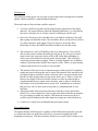
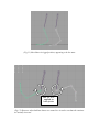
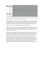
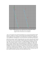
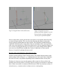
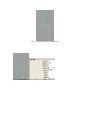
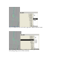
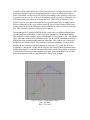
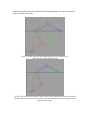
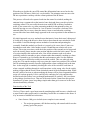
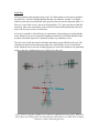
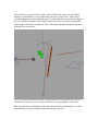
INNOVATIONS REPORT
AUTOMATATED BIPED CHARACTER SKELETON
AND CONTROL RIG GENERATION in Maya
By James Nicholl
Abstract
This paper looks at the processes used in creating an auto rigging procedure for use in
Maya, using the in built language MEL. In order to better understand what was required
for this task research into rigging techniques and practices was undertaken. These include
general practices adopted when creating bone chains to help both the rigger and the
animator who will use the rig. In addition there was an in-depth exploration of specific
techniques such as IK/FK switching.
What is a rig/rig generator and its uses
A character rig can be defined as a skeleton and set of controls which are used to move
and deform a character mesh. These controls will be used by animators in order to create
character animation. The process of creating a character rig can be a time expensive
process. The purpose of a rig generator is to cut down the time needed to create a full rig
ready for animation. However it should be noted that a tool such as a rig generator is not
a complete solution to rigging. It’s not a replacement for a good character rigger and
couldn’t be used every time. Not every character is going to have the same needs, the
production may need to create a character with four arms each with 6 fingers and one leg.
This would require a specified rig that would be very hard to script as it is highly unique.
It wouldn’t be very practical to create a script for this either as it probably won’t be often
you’ll encounter the need to rig a character such as this. If a production needed a number
of characters of the same height and build then the 1 rig could be built and applied to
many characters. However if the proportions varied wildly this method would not be
appropriate. This would then result in someone creating various rigs to match the
requirements of each character mesh. This process can be sped up with the use of an auto
rig tool. The best application for an auto rig is something that creates a good generic base
or starting point for further development. It also has other useful applications such as
when multiples of similar character needs to be rigged quickly. If a script can be created
to generate something that is in between what is needed it should be quick to adapt this to
all the characters. This is a lot quicker than making 100 characters from scratch each
time. It is also very useful for people with no rigging skills. They might have a character
they have modelled but not be able to animate it. Using an auto rig would mean it would
be very quick for them to get to that stage.
Challenges set
The challenge of this project was to create a script in Maya that could generate a skeleton
and the controls needed for a modelled biped character.
The main features of this tool that would be required –
•
To create a solid base rig that could be adapted to the proportions of any biped
character. The output character should be adaptable and robust, e.g. not break the
first time a character uses it. Or have controls so baffling it can’t be used.
•
Ease of use for the user, they shouldn’t have to be bothered with any of the stuff
that is going on behind the scenes. They should be able to use the tool even if they
very little experience with rigging. They will, however, need some basic
knowledge of what is IK and FK and which would be best for their setup.
•
The inclusion of a sense of flexibility to the rig creation process. Users will be
able to make choices which will modify the out put rig. E.g. the type of control
made for the body such as the choice of IK or FK for the arms depending on
which is the most suitable for the task at had. Stretchy limbs. This will require
researching current trends in rigging. What is currently thought to be as standard
within a rig and what other features users require or like. There’s no point writing
a function that will never be used as it is not needed.
•
The interface of the tool is also an important aspect of the tool itself. It should be
simple and concise allowing the user to tap the full potential of the tool while still
providing all that is needed. In certain cases tools can be very powerful but if the
interface is badly designed the user may not be able to use it. There is a fine line
between too simple so the user has little control over what is produced and so
complicated that the user cannot create what they want or where it would have
been simpler to do it manually than to use the tool. It should also be created so
that processes can’t be done in the wrong order e.g. implementation of error
checking.
Split up repeatable tasks into many functions so that they can be called when
needed. E.g. create a function to create a single arm which could then be attached
to a pre-existing rig which was armless. This makes the tool more useful as it
could be used for multiple tasks rather than just creating one whole finished rig.
•
•
Creation of a visually clear and helpful bone placement system.
The method I chose
The approach taken with this project is perhaps a little different than generally expected.
A conscious decision was made not to look at any current auto rigging tools at the
beginning of the project. I felt that I needed to do this so as to give myself a chance to try
and develop the tool from my own understanding of what was needed. I have found from
previous experience that when I have researched something I tend to get hooked into the
method that that person used and end up either modifying that for my needs or sometimes
just copying it because I find that it is already a proficient method. In the case of this
project I wanted a chance to create my own theories on how to achieve effects that I
wanted and once I had finished the project I would go back find some examples of how
others had tackled this problem and how our methods compared. This way I feel like I
have actually gained more from doing the project. I did however research into rigging
techniques used at present as this was needed to see what would be demanded of the rig
that was generated. Doing this would help me to create a much more rounded tool as I
know what is required of the rig. Coding wise it forced me to delve into MEL
programming a lot more. Sometimes it can take longer trying to figure something out
yourself and you may not create something as efficient as someone else’s but when you
go back you have a better understand of the problem itself. You know what others have
had to try and solve and why. This gives you I find a better grounding in understanding
how they will have gone about creating their solution.
Most of my knowledge gained is in the rigging techniques I was not aware of before
Basics Rules of Rigging learned
There are some practices that should be observed when creating a bone chain for a rig
that some users may not be aware of. These, while not set in stone are good guidelines as
they will ease work later on in productions. A couple of the most important are:
•
•
•
Bone Orientation
Rotation Order of Bones and controls
How these effect the rigger and the user e.g animator of the rig
One of the most important things to be aware of is the orientation of bones when they are
created. When bones are created in a chain they align themselves in certain ways
automatically to point towards the child. However sometimes this aligning can go awry.
A good example is when creating a bone chain for the spine. If your bones had various
orientations when you wrote a script to rotate all the bones in the x axis to give a nice
bend to the spine you may find that your bones rotate in opposite directions. Creating a
common orientation throughout your rig can help the rigger themselves and the animators
also as errors are less likely to occur when controls are created.
Another good reason for is for the animators benefit. For example if they had one leg
chain that rotated backwards in the knee in negative z and the other in positive z it could
cause some issues. The animator would still be able to use a control to individually move
a leg, key it and then go to the next frame and key it and so on. If they tried to rotate both
the joints at once in the z-axis it would be found that the legs would rotate in opposite
directions.
(Fig 1.1) Knee Bones in rigged position, appearing to be the same
Rot -85 in Z
applied to
both joints
(Fig 1.2) However when both knee bones are rotated in z it can be seen that the rotations
are actually inversed.
While this problem could be avoided by moving each chain individually or might be
overlooked because the legs are never moved together another problem would arise when
it came to editing the timing of the piece. In the graph editor it would be hard to discern
the true movement of the bones. The legs of the character might be moving the same way
in the view port but in the graph editor the animation curves for both legs would actually
be opposite. This could cause confusion for the animator as they might not have realised
that the bones rotations are actually the inversed. From their perspective in the graph
editor the animation curve is telling them that one leg is rotating in the opposite direction
to the other. Even if they had realised that this was just because the bones were orientated
differently it still makes if difficult to retime the animation using the curves as they
couldn’t be modified at the same time. Each curve would need to be modified separately
basically meaning twice the amount of time and effort and this would not be good for the
production in general as it would delay it just because of this small oversight in the rig.
Fig (1.3) View of the local rotation axis
Fig (1.4) The bones in this diagram appear to
have been rotated by equal amounts.
Fig(1.5) & Fig(1.6) Actually looking in the channel boxes shows that the rotation values
in Y are actually different
Fig (1.7) Animation curves of the knees above. As they are opposite retiming could take
twice as long as keys will need to be moved individually
Another common practice that ties in with this is making sure rotation values are set to 0
by default. It makes it a lot easier for a user if they can get back to the default position of
the joint by just entering 0 rather than a completely irrelevant number such as 62. Again
it makes it a lot easier to compared animation curve in the graph editor if everything
starts from 0 as it is easier to relate and compare things to each other.
Although the concerns listed may seem inconsequential and a mild inconvenience for the
rigger at creation time it can be seen that in actually fact these tiny things can cause a lot
of trouble. When creating a rig the fundamental thing is to make something that is easy
and robust for the end user.
Having uncovered the above information when creating the auto rig I came across some
problems when creating the script for generating the skeleton of the rig. Initially I had
planed that the user could place a locator object where they wanted the bones for their
character to be created. However, when the bones where created in place by the script it
became apparent that none of the bones orientation had been calculated evaluated
correctly The bones had been created with their local orientations aligned to that of world
space instead of each bone looking to where the next one was. This caused some huge
problems when trying to actually use the bones for driving the character as can be seen in
the image below. No matter which axis you rotated around it was unable to create
correction direction of rotation that matched the way the bones should be going. See fig
(2.1).
Fig(2.1) Comparison of a correct and incorrectly orientate bone chain
Left side bone chain with incorrect orientated.
Right side bone chain with correct orientation.
The re-orient joints tool was used but found that it gave varying and inconsistent results.
Therefore a method was needed to create the bones in the positions defined by the user
while keeping the correct orientations. One method tried s was through a combination of
vector mathematics. By finding the vector between the start joint and end joint the plane
defined between these could be found and therefore the normal to that plain which should
have given me all the vectors I needed to align the joints local rotation axis. However the
user doesn’t have to have placed the knee in a straight alignment with the hip and foot
joints. They could have made it so the knee was turned out slightly. This I knew could
still be solved by maths but it got a bit to confusing for me and therefore I fell back on
using a technique I had developed for IK/FK switching (described later). By creating an
IK handle between the foot and the leg it could move the position of the leg while the IK
would keep everything in perfect alignment. The pole vector of this IK is controlled by a
control object which is positioned at the knee. Once this is done the bones are now in the
correct alignment defined by the user and also orientated correctly e.g the bones have all
been created on the plane defined by the locators placed by the user.
Fig(2.2) Original bone chain and locators
Fig(2.3) Top bone in correct
positions and bone aligned correctly
however bones not long enough to
correctly fix to positions defined.
However these bones weren’t placed in the exact places as I now didn’t know how long
to create the bones initially. This was solved by measuring the distance between the
locators using the distanceBetween node in Maya. After both these methods had been
combined I could now place a bone chain of any size and shape in the correct positions
with correct local rotation axis. While this method works I am not completely happy with
it as it seems a bit sluggish and long as it requires me to create multiple nodes which in
most cases are deleted almost straight after creation. I think that is a little wasteful.
However I reused it for placing the arms as well.
Rotation Orders and splitting the control between joints
Another common problem is that of rotation orders. The standard default rotation order
when creating a bone in Maya is x y z. Although it doesn’t arise much I have found that
this order can cause you problems depending on the orientation chosen for the joints.
The hips of a character are an area that needs to able to rotate in all axis as this is the
freedom of movement you have in real life. However trying to get one bone to control all
three of these movements is extremely difficult because of the way rotations are done. If
a bone has an x y z rotation order it evaluates axis in a certain priority.
Fig (3.1) Starting point, all rotations 0
Fig (3.2) Rotation in z, only z gains any value.
Fig (3.3) Rotate in the y axis, only y gets any. Value z stays the same.
Fig (3.4 Lastly when adding a rotation in x only x gets a value.
Everything thing seems to work normally.
However once you try and rotate again in y or x you will find that all 3 rotation values
start to change. In fact if you had rotated in x first and then y you would have also found
that all 3 axis would have started gaining values. This problem can be alleviated by
changing the rotation order of the bones if you were only requiring two of the axis. With
3 though the same value breaks occur. In situations like this it is best to create a second
bone with which two split the rotations between. This can be placed in exactly the same
position of the other bones and can be used to take control of one of the axis. Therefore
one bone controls 1 axis while the other controls the other two. Giving all 3 rotations
without the problems listed before. This is exactly what I have done on the spine
generated by the script. The root controls the y and x axis of the hip movement while the
hips control the twisting motion. This was required because the spine twisting controls 2
clusters further above it. When I started rotating the root with all 3 axis it would come to
a point where the spine would twist when it was not expected or wanted. Splitting the
control between the root bone and hip bone was the perfect solution.
A method of IK/FK switching arms without using blends
One aspect of the rig which is fiercely regard this day is the need for IK/FK switching
arms and was something I was keen to look into. This method of rigging implies having
both IK (Inverse Kinematics) and FK (Forward Kinematics) system in place to be used
by the animator. With the increasing demand of motion required from an animator this
system is almost a prerequisite. IK is generally used when part of the body say the hands
needs to be fixed in space while the animator has the freedom to move the rest of the
body without effecting the position of the hand. A good example of this would be if a
character needed to place their hands on a table and have them stay there though the rest
of their body was moving. If the animator was using an FK system for this sequence it
would be extremely difficult and time consuming, as the body moved the hand would
travel with it. Therefore for every keyframe the hand would need to be repositioned to be
in contact with the table and be in as close to the position it was in the last keyframe. This
matching of position is the time consuming part and a degree of sliding from frame to
frame is inevitable. On the reverse, FK has major advantages when creating a walk cycle
or gesturing. In the case of a walk cycle the animator needs to be able to create nice arcs
of motion for the arms as they move beside the body. With an FK system this is very
simple as you can just rotate around the elbow to give the hand a nice swinging motion.
However doing this in IK is very difficult as the IK solver effects all bones in the chain,
meaing when you move the IK handle both the hand and the elbow will move at the same
time. This can make it hard to create nice arcs of motion.
The fundamentals of creating an IK/FK switch system isn’t very difficult although there
are many different solutions for it. One of the most common is a 3 bone chain method.
This method as it name suggests, uses a combination of 3 bone chains, 1 FK, 1 IK and the
bones chain that will be used to deform the mesh. The IK and FK bones both control the
deformation bone chain through orientation constraints. This is where one of the major
problems of this method arises. The orientation constraints weighting is what controls
which bone has control over the deformation rig at any time. E.g. when the IK bone’s
weighting is 1 and the FK’s 0 then the IK bone has full control of the deformation bones
and the when the FK is 1 and IK 0 then the FK has full control. The problem or irritation
is when u switch from one control method to the other your deformation bone will slide
between the positions of the 2 controlling bones. Below is an example.
Fig (4.1) Green = Deformation Chain
Red = IK chain
Blue = FK chain
In this picture IK bone has full control of the deformation bones. As it is moved the FK
bones stay in the same place.
Fig(4.2) As the control of the deformation chain is switched it will
slide between the IK and FK chains
Fig (4.3) FK now has full control of bone. However the FK bone will need to be moved
into the same position before keying otherwise the deformation joint will jump from one
position to the other.
When the user decides they need FK control the deformation bone moves back to the
position of the FK bones, which isn’t very desirable. The animator must now move the
FK into a position to catch up with the current position of the IK bones.
This process will need to be repeated each time the control is switched, making the
animator keep a constant tab on the inactive bone chain and always catch it up before
switching control. This was really the main issue with IK/FK switching I wanted to
tackle. It just seems to be very time consuming method for the animator as they are
basically moving two sets of bones for 1 set of motion. It would be a lot better if the
animator didn’t have to worry about the inactive bone set and when the switching
occurred the other bone chain simply appeared in the correct position for the animator to
use.
My initial approach was to try and make sure that inactive bone chain wasn’t being used
it would move along with the active bone chain so that when the user switched it would
be available. I tried this through various methods of constraints and parenting but
eventually found this method was flawed as it caused cyclic errors where 2 joint were
dependant on each other. After further research I found that one solution was to use
scripts. This script at run time would check the position of the currently active bones and
move the inactive bones into the same position and then switch the bone control. The use
of a script simplifies this task much more. Now all the animator needs to do when
switching control is remember to press a button rather than manually catching up a bone.
However I wanted to go a bit further than this and attempt to make it so the animator
didn’t even have to do this but could just switch the control. This was achieved using
script jobs. This ran the catch up script every time the control was switched. This worked
fine for animating but actually caused a slight problem when scrubbing back in the time
line. As the script job is constantly checking the value of the switch for each frame it
when u stopped scrubbing through it could sometimes set the wrong value for the switch,
making it appear that the inactive bone chain had control of the deformation chain. While
this isn’t much of an issue as when rendering the frames will be played sequential and the
script will evaluate properly I felt it could be a bit confusing for a user and therefore
decided to take this feature out even though fundamentally it worked. I felt it was better
to keep things clear than clever. That one of the main lessons I learnt from this project.
Sometimes it is better just to keep things simple rather than go for seems to be the most
advanced and flashy solution.
Functionality of the Tool
I feel as if I have made a good start towards something that could become a valuable tool
to myself and to other people and it is something I would like to continue in the future. It
is by no means a finished tool at this time.
•
Some features I did get to include (more complete in user manual)
o The script can generate a full skeleton and rig with controls which was the
primary goal of the project
o Can create a full rig using the default settings and placement extremely
quickly with minimum user input.
o The rigs, while all for a biped, can vary wildly proportionally.
o All controls generated for the rig will always be roughly the correct size
for any size rig created.
o Some freedom of choice as to the type of rig it will create eg user can
choose what type of arm controls they want IK FK or both, number of
bones created for the spine, stretchy leg IK.
o All driven keys for feet and hands are pre-set by the script and assigned to
control objects.
o Ability to choose to create only parts of the body rather than a full body.
o IK/FK switch without blending, did that because seems like a demand and
good idea
At the present time the flexibility of the tool is far inferior to what I would have liked.
Although I may be being a bit harsh on myself as I actually found creating the main
functionality of the tool more work and required more scripting than I had initially
foreseen. I am still quite disappointed that I couldn’t get it to a stage where people could
customize the rig created better to them. At the moment everything is quite fixed to my
way of working which is something that I didn’t want. The user should feel like they
have made this rig and therefore would feel more comfortable using it but I don’t feel this
is achieved. For example the naming conventions are catered to me using the rig rather
than someone else and it could cause some hassle for the user to find a joint that they may
have named differently had they creating the rig themselves from scratch. It would have
been very helpful if the user could have a choice in customizing the naming as it would
make it feel more personal. I think, people are more happy to work with something they
have created for themselves, it feels more familiar, they know why that is called that
because they made it like that and so on, nothing alien can pop up to confuse them.
I also didn’t get as far as to make the tool able to create controls for a skeleton that had
already been created. This is another reason I feel my tool is quite inflexible in place.
Again it makes it more personal and familiar to a user if they feel they are working on top
of something they have created themselves. I did foresee that this was a feature I would
want at some point even if it wasn’t available for the hand in and therefore the code is
actually split the way it is so that this function could be added to the tool fairly easy. At
the moment it would requite adding a large amount of new code. I would need to modify
the tool interface to allow the user to input there bone chain names and then have the
functions for creating the controls working on those. I would also need to redesign the
main user interface as it would need to have all new text fields for entering the names of
pre existing bones. I’d also still need to keep my defaults I have now just in case a user
didn’t want to create there own names.
Think I have accurately pre-empted people’s needs and requirements function wise. This
done through combination of looking at what other rigs at the time offer, from personal
experience and from asking people what they would want from a tool like this. The final
rig created is fairly robust and useable.
Future Functions Wanted
•
•
•
•
•
•
Would like to develop the tool further. It seems like something that would be
worth while doing.
Ability to create the rig facing in any direction. At the moment it can only
generate rigs facing in the positive z.
Extra tool set to help making rigging easier. For modelling you now have
features such as select edge loops and ring loops. It could be useful to create
some mini tools that might useful to speed up rigging of some tasks. For
example one thing I find frustrating is adding a bone between 2 existing bones
that are linked. The new bone needs to be created with an orientation that is
going to match with the 2 current bones. The method I use for this can take a
while and you can have to do it quite frequently. to do so I can see an opening
to create a tool to simplify this task.
Would like to look further into more advanced rig techniques, such as space
pinning, broken hierarchy, palm IK, IK fingers. These are all things that I read
about while during researching but weren’t really a necessity for this early
version of the tool and I also don’t have the necessary knowledge to
implement them into the tool at this time.
Thumb needs making still. I just couldn’t figure out exactly how it would need
to be made.
Wrist broke
User Interface/Interaction
I think one of the major downfalls of my tool at the moment is the user interaction. It’s
not as easy to use as I would have liked. I didn’t really realise this until I gave it to some
people to test. My primary goal was to get the main functions creating the rig working
first and the interface was more of a secondary thought. This turned out to be more
challenging than I had expected or at least a lot more involved to get things working as I
wanted. Therefore the interface got very little time and I think the tool as a whole has
suffered from this lack of research and detail.
The visuals of the bone placement needs a lot more work. There need to be a lot more
universally recognisable visuals to help with the placement of the bones. The current
system is better than just the locators as these had the problem of being quite confusing. I
tried to counter this by creating the locators in the formations of the bone parts they were
going to be used for e.g. creating the leg locators in a rough leg formation. However as
there we no connections between them it could just look like a series of random placed
locators in space. Another problem with locators is they all look the same. This could
cause problems where locators could swap positions and the user might not realise. For
example you could move the shoulder locator to the position of the elbow and the elbow
to the shoulder position and visually there would be no hint that this had occurred. To try
and counter this I have added connections between locators so that you can see if you
have flipped stuff. From feedback by some test users they said that the new connections
were defiantly an improvement but I have only put them on certain parts of the body and
therefore continuing the theme would be a lot of help. Especially on the spine area which
is still just a group of locators. However even this method is still flawed some parts of the
body would still look the same if swapped. I think that more time needs to be spent over
discussing with users how they would feel most comfortable using the tool. Getting user
feedback earlier in the project is something I now wish I had done as it probably would
have meant for a more rounded tool but I know for certain that a clearer method for
placing the bones is now needed.
Coding
The general standard and understanding of coding has improved during the course of the
project. As I have been going back and tidying up the code I have found that this means
the standard of the code varies from function to function. There is still a lot of room for
improvement and some of the code seems quite verbose. Also forgot there was a vector
class in MEL so I kept on creating my own arrays to store 3d positions. In a lot of places
things are hard coded in despite my best intentions. As a result to add more functionality
too the code as I have stated would probably require a good deal of rewriting the code.
User feedback
The tool was given to a few people to try to use, so as to gain information on various
accpects
“The general idea of the tool is a good one but the interface is a bit hard to follow and
isn’t very well commented”
“The controls created around the hand aren’t very clear as to what they do. Also there are
so many controls around the hand that it becomes to crowded and hard to select what you
want”
“Its quite hard to determine what the layout of the skeleton should be, perhaps an
example of how it should look would be a good idea.
“The tool wouldn’t work for me, the placement pipes were made in the wrong place away
from the other controls”
Generally the main problem at the moment seems to be that the interfaces are badly
designed and the user is unable to understand how to use the tool as I had feared and
stated above. Effectively the interface is actually stopping people being able to use the
tool.
Major Bug
One big problem at the moment is bug I can’t fix which makes it so the tool is unusable
by some users. At first I had thought that this bug was limited to version 6.5 of Maya
which was not discovered until late in the project as the tool was developed in Maya 7.0.
However 1 out of the 4 users, who were all using Maya 7.0, I got to test the tool had the
same bug. After some research the cause of the error has been found but there does not
seem to be any way to solve it at this time.
As far as I can deduce so far this bug is a consequence of generating curves through the
script. When the curves are generated something essential is overlooked and this results
in errors when other objects are connected in some way with these curves.
The first error is with the visuals of the bone placement system utilised by the user. The
cylinders used between the placement spheres are controlled by curves created by the
script. When the curves are not evaluated properly it causes the cylinders to be generated
in the wrong place, hindering the user’s ability to use the tool.
Fig (5.1) Due to bug the cylinders are created in compleltly the wrong place. While this
won’t effect the working of the tool when the placement spheres are moved the cylinders
still move visually distracting the user.
The second error occurs when the spine is created. The spine consists of an IK Spline
which is created based on a curve generated by the script. As the curve, again, is not
evaluating properly it means when the spine is created using the curve it does not align to
the curve properly. Instead of following the path of the curve as would be expected the
spine chain is created in a straight line. This is obviously unusable and renders the spine
function of the tool useless.
Fig (5.2) Spine created incorrectly due to bug. Green arrow is the path of the curve it
should have followed and the red arrow indicates the wrong alignment it has taken
This will need to be something that will need to be looked into in the future as it would
be unfeasible to create a tool that could not be used by ever user.
Future Project Thoughts
•
Better planning of what functions will be needed, how to structure them within
the code so there is a better flow. Efficient, less repeating code. Initially I just
thought about the splitting the code into the main body parts I would be
generating. E.g. an arm or a leg. This however looking in hind sight wasn’t a great
way to start it. I ended up spending more time trying to combine all these codes
into one tool and have them interact with each other well. Also once this was done
I had to adapt them all again so that they would work well with the interface and
making sure I could make them work for both sides of the body. Concatenating
took me a long time. If I had planned out my work flow a bit better I think I could
have avoided so much re-coding and inconsistency in the code. I should have
planned for the flexibility from the beginning.
•
Should really sit down and think what I will be needing. What does the user want
and why, how can I make this task easy for them. Need to keep an over view of
how functions will need to be interacting with each other later on. Take more time
thinking about the users needs. Keep it simple and usable not flashy and
overcomplicated.
•
Orientation extremely important. Things can get very broken otherwise as I have
already demonstrated. This is something I wasn’t really aware of before this
project but is something I will take into account when making future rigs.
•
Visuals are very important. Designing an interface requires time to create and is
defiantly something not to be over looked. The tool could be very capable but
can’t be used by the user because it has been over complicated. Make sure it does
the job it was designed to do first and foremost and that the interface can take full
control of this.
•
Reverse foot lock with bones is not a great approach, it can cause problems where
it is not adaptable enough for future development or updating. This something I
will need to look into a bit more in the future. Try to create a setup in the rig
and/or in the tool which makes it easy to update. It’s not good if to change the
way one bit works you need to delete all that you had before and rework it all.
•
I feel that the code is quite verbose in places. I know that it could be cut down in
places quite easily. Lack of some maths knowledge is frustrating as it has severely
hindered some of the coding as I have had to do things the long way. It ends up
feeling quite sluggish. If I looked up the maths I could probably make it more
efficient. For example I have cases where I create 3 or 4 nodes which are used
very briefly and then completely deleted very shortly afterwards, when in reality
there is probably a method that required me not o make them in the first place.
•
Lack of the choice of orientation methods. XYZ , ZYX and so on.
Conclusion
In conclusion I feel the project has been successful providing better grounding in rigging
techniques and practices that will be an aid when continuing this tool at a later date. By
approaching the project without looking at any previous auto rigging tools, it is now, at
the end, when I feel ready to look at what is already available. Although I feel the
approach may have slowed progress in some cases where solutions to problems were not
easily discovered. From the exploration taken in this project I know what base knowledge
has had to be gained in order to better understand the problems of creating an auto
rigging script. When comparing the project tool to a finished auto rigging tool now I feel
I will be able to draw better conclusions as to why a particular method was used in favour
of another and possibly see that how my tool has been created was not actually the best
way. A major part I am now interested in is how the creators have tailored it to the end
user as this is the part of the project that fell short and needs the most effort put back into
it. In short the tool that has been created during the project has turned out to be a
prototype, even though it was not intended as such, which has helped me gain the
information I need to go away and create a complete tool.
References
Books
Ritche Kiaran, Callery Jake, Biri Karim
The Art of Rigging – Volume 1, CgToolkit
Articles
Shcliefer, Jason - AWGUA Maya Master Class August 2001
Integrating an animation rig into a creature pipeline
Shcliefer, Jason
Fast Animation Rigs – Bridging the gap between speed and functionality
Bell, Steven
Writing your innovations report
Obtained online from : http://ncca.bournemouth.ac.uk/sbell/notes
Websites
Ncca Forum – Online cg Forum
Available from :www.nccaforum.co.uk
Accessed daily from Jan 2006
Schliefer, Jason – Online Rigging Forum
Available from : http://jonhandhisdog.com/forum/index.php?showforum=4 –
Accessed weekly from Feb 2006