1
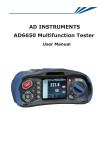
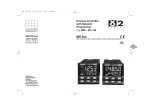
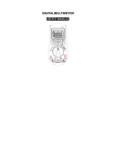
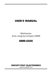
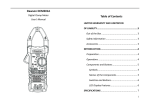
APS-9301 & APS-9501 & APS-9102 User’s Manual
APS-9301 & APS-9501 & APS-9102 User’s Manual
Contents
1.
2.
3.
4.
5.
6.
7
8.
9.
9.1
9.2
Safety terms and symbols……………………….……….
Installation………………………….………………………..
Operation……………………………………………………..
Panel Description…………………………………………..
Calibration …………………………………………….…..
Circuit Principle……………………………………………
Block Diagram……………………………………………...
Specification…………………………………………………
Maintenance…………………………………………………
1
2
4
8
11
14
15
16
18
Cleaning…………………………………………………….. 18
Troubleshooting…………………………………………… 18
1. SAFETY TERMS AND SYMBOLS
These terms may appear in this manual or on the product:
WARNING:Warning statements identify condition or practices
that could result in injury or loss of life.
Caution:Caution statements identify conditions or practices that
could result in damage to this product or other property.
The following symbol may appear in this manual or on the product:
Attention refer to Manual.
1
APS-9301 & APS-9501 & APS-9102 User’s Manual
2.
APS-9301 & APS-9501 & APS-9102 User’s Manual
5.The size of input wire and output wire.
Installation
1.Before installation, please make sure the AC input voltage is correct.
a.The AC input voltage of APS-9301/9501 is either 115V or 230V,
which can be selected. The select switch is located on the rear panel.
Model
APS-9301/9501
APS-9102
Input Wire Size
115V
230V
AWG#14
0.75mm2
AWG#12
Output Wire Size
AWG#18
2* AWG#18
6.An AC power cord is packaged in the unit of APS-9301/9501 as
accessory.
sel ect swi t ch
V
0
3
2
7.The Selection of Output Test Lead:
b. The AC input voltage of APS-9102 is fixed either at 115V or 230V,
For safety reason,Do not make any change by you own to avoid
damaging the instrument.
2.Before plugs input power cord to the suitable outlet or connects the
input wires, please make sure all the APS-9301/9501/9102’s breakers
are turned off. It will avoid the unnecessary accident or damage to
APS-9301/9501/9102.
3.Plugs the input power cord to the suitable outlet or connects the input
wires/cable to the input terminal block which is located inside panel of
APS-9301/9501/9102. Please make sure the connections are very tight
which may avoid some problem happening.
4.Please make sure the input tolerance of this APS-9301/9501/9102 is
within ±15% of rated voltage (see figure 1)
Max
Output
Voltage
For safety assurance, please select the
lead according to the following list:
UL
Conductor
(CSA) Wire Component Cross Outer
Model No.
pc/mm Section Diameter
Area
AWG
mm
2
(mm)
24
22
20
18
16
14
12
10
1015
TEW
(Twisted
Wire)
11/0.16
17/0.16
21/0.18
34/0.18
26/0.254
41/0.254
65/0.254
65/0.32
0.22
0.34
0.53
0.87
1.32
2.08
3.29
5.23
0.64
0.78
0.95
1.21
1.53
2.03
2.35
3.00
adequate output test
Maximum
Conductive
Resistor
Ω/km
88.6
62.5
39.5
24.4
15.6
9.90
6.24
3.90
Permissible
Current
A(amp)
7.64
10.0
13.1
17.2
22.6
30.4
40.6
55.3
Remark:
1.
150/300
120/240
120/240
2.
100/200
3.
100
85
90
95
115
The ambient temperature of “Permissible Current” is at
40℃, the withstanding temperature of conductor is at
105℃ according to the condition of the distributed
single wire.
The permissible current listed as above is suggested to
be used under 70%.
When the current value exceeds above suggestive list,
can select more wires used in parallel according to
above list.
% of Rate
Input Voltage
Figure 1.
2
3
APS-9301 & APS-9501 & APS-9102 User’s Manual
APS-9301 & APS-9501 & APS-9102 User’s Manual
h. If any key mentioned above is not pressed for 2 seconds continuously,
APS-9301/9501/9102 would go back to the normal operation and
the voltage display could show the reading value automatically.
3. Operation
1.Voltage Setting:
Voltage setting contents ‘110V ’, “ 220V ’, ‘▲’ and ‘▼’ four keys.
a. When any one of the keys mentioned above is pressed, the voltage
display will flash one time, the APS9301/9501/9102 will go to the
setting mode and show the voltage setting value.
b. If the ‘110V’ Key is pressed, the output voltage will be adjusted to
110V immediately. Meanwhile, the voltage display will switch back
to the reading mode automatically.
c. If the ‘220V’ key is pressed for 0.2 seconds continuously ( for safety
reason, must be), the output voltage will be adjusted to 220V.
Meanwhile, the voltage display will switch back to the reading mode
automatically.
Note: It would not work if the output voltage is setting on low range.
(0~150V output)
d. If either “▲” or “▼”key is pressed for 0.5 seconds continuously, the
output voltage will be adjusted. If either “▲” or “▼” is pressed twice
continuously, the output voltage will be adjusted immediately.
e. The adjusting rates are 0.1V/step on fine adjust mode and 1V/step on
coarse adjust mode.
f. The first six steps of adjustment will be spent 0.25 seconds per step. If
the key “▲” or “▼” is pressed continuously, it will spend 0.13 second
per step for the rest steps. If the key is released, the voltage
adjustment would be stopped and go back to the original adjustment
speed (0.25 seconds per step) automatically.
g. If the output mode is setting ON ( the indicator ‘OUTPUT’ would light),
the output voltage could follow the setting voltage simultaneously
Caution: When you adjust the voltage at “▲” or “▼” mode, it is
better to switch off the output to avoid unnecessary damage
because of accidental voltage adjustment.
4
2.Frequency Setting:
Frequency setting contents ‘50Hz’, ‘60Hz’, ‘▲’ and ‘▼’ four keys.
a. Either the key ‘50Hz’ or the key ‘60Hz’ is pressed, the frequency will be
changed immediately to 50Hz, 60Hz respectively. Meanwhile the
output frequency will be changed coincidentally.
b. The frequency ranges from 45Hz to 99.9Hz can be adjusted by 0.1 Hz
per step in fine adjustment mode and 1 Hz per step in coarse adjustment
mode. The frequency ranges from 100Hz to 500Hz can be adjusted by 1
Hz per step in fine adjustment and 10Hz per second in coarse
adjustment mode.
c. The other setting are same as voltage setting.
3.High / Low Voltage range selection:
Press the key of ‘RANGE’, if the indicator lights, the output voltage
would be setting on the high voltage range, otherwise, the system
would be setting on low voltage range. The changed range would not
cause the setting voltage to change, however, there is a 20ms
interruption during the voltage range changing. The non-reasonable
range changing (For example, the voltage sets 200V but the range is
changed to the low range) is not acceptable by APS-9301/9501/9102.
Note: High range voltage 0 ~ 300V
Low range voltage 0 ~ 150V
4.Instrumentation selection:
a. Press the key of ‘A’, the indicator of current will light and the LED
display will show the value of current.
b. Press the key of ‘W’, the indicator of power will light and the LED
display will show the value of wattage.
c. Press the key of ‘PF’, the indicator of power factor will light and the
LED display will show the value of power factor.
5
APS-9301 & APS-9501 & APS-9102 User’s Manual
APS-9301 & APS-9501 & APS-9102 User’s Manual
5.Output Enabled and Disabled Operation:
Press the key of ‘OUTPUT’. If the indicator of output lights, the output of
APS-9301/9501/9102 is enabled, all the LED display will show the output
value (reading value). Otherwise, the output function is disabled, and the
LED display will show the setting value. Press the ‘OUTPUT’ key again
to change the mode.
6.Lock Function:
Press the key of ‘LOCK’. If the indicator of lock lights, all the keys are
Locked (except the alarm reset). This function is good for avoiding any
mistakes of key pressed during operation. Press again to change the mode.
7.Alarm Reset:
If there is over current happened, APS-9301/9501/9102 would be shut
down and buzz immediately. You must press the key of ‘ALARM
RESET’ to clear the fault of over current and stop the buzz. In addition,
the key of ‘OUTPUT’ have to be pressed to get the normal output voltage
again.
8.Memory Function:
As APS-9301/9501/9102 is equipped with EEPROM, the latest setting will
be memorized after the unit is turned off. If the APS-9301/9501/9102 is
turned on again, the latest setting will be displayed.
9.Save/Recall Function:
Press the key of ‘S/R’, if the indicator of SAVE/RECALL doesn’t light,
Press any one of keys ‘MEM1’ ‘MEM2’ ‘MEM3’ and ‘MEM4’ for 0.2
seconds, the current output setting will be saved. If the indicator of
SAVE/RECALL lights, press any one of keys ‘MEM1’ ‘MEM2’ ‘MEM3’
and ‘MEM4’ for 0.2 seconds, the setting saved last time via the same key
will be recalled as current settin
6
7
APS-9301 & APS-9501 & APS-9102 User’s Manual
APS-9301 & APS-9501 & APS-9102 User’s Manual
4. Panel Description
(12)Output Voltage LED Display
If the ‘OUTPUT’ Key is not pressed, the indicator doesn’t light, and the
setting value will be displayed on the Output Voltage LED Display. If the
‘OUTPUT’ key is pressed, the indicator lights, and the output value will be
displayed on the Output Voltage LED Display.
(1) ‘ALARM RESET’ Key
Reset key to cease the buzz and reset the output.
(2) ‘S/R’ Key
Save or Recall function selecting key.
(3) SAVE/RECALL indicator
In the mode to save setting, the indicator doesn’t light. In the mode to
recall setting, the indicator lights.
(4) .(5) .(21). (22) ‘MEM1’ ‘MEM2’ ‘MEM3’ ‘MEM4’ keys
When the SAVE/RECALL indicator is off, the four keys are for saving
four different settings. When the indicator are on, the keys are for recalling
the saved settings.
(6).(23) ‘50Hz’、‘60Hz’Keys
One touch key for 50Hz and 60Hz output respectively.
(7) Output Frequency LED Display:
If the ‘OUTPUT’ key isn’t pressed, the indicator doesn’t light, and the
setting frequency value will be displayed on the output frequency LED
display. If the ‘OUTPUT’ key is pressed, the indicator light, and the output
frequency value will be displayed on the output frequency LED display.
(8).(24). ‘▲’ 、‘▼’ Keys
The two keys are for frequency setting, to increase or decrease the
frequency value respectively every time they are pressed. The adjusting
rate depends on the ‘COARSE’ key and the frequency value itself.
(9) Coarse Indicator
If the coarse adjustment mode is selected, the coarse indicator will light.
If the fine adjustment mode is selected, the coarse indicator does not light.
(10)High / Low Range Indicator of Output Voltage
If this indicator lights, the output voltage is in the range 0 ~ 300V. If this
Indicator does not light, the output voltage is in the range 0 ~ 150V.
(11).(27). ‘ 110V ’, ‘ 220V ’ Keys
One touch key for 220V and 110V output respectively.
8
(13).(28). ‘▲’、‘▼’ keys
The two keys are for voltage setting, to increase or decrease the voltage
value respectively every time they are pressed. The adjusting rate depends
on the ‘COARSE’ key.
(14)Function of Ammeter Indicator
If ammeter’s indicator lights, the value of output current will be displayed
On the multimeter LED display.
(15)Function of Wattage Meter Indicator
If wattage meter’s indicator lights, the value of output wattage will be
displayed on the multimeter LED display.
(16) Multimeter LED Display
The value of output current, wattage or power factor will be displayed by
respective key from ‘A’, ‘W’, to ‘PF’.
(17) Function of Power Factor Meter Indicator
If power factor meter’s indicator lights, the value of output power factor
will be displayed on the multimeter LED display.
(18) ‘OUTPUT’ Key
Output function enabled/disabled selection key.
(19)Output Indicator
When output is enabled, the output indicator will light.
(20)Power Switch
To turn on /off APS9301/9501.
(25) ‘ COARSE ’Key
Coarse/Fine adjustment selection key.
(26) ‘ RANGE ’ Key
For the high / low output voltage’s range selection.
9
APS-9301 & APS-9501 & APS-9102 User’s Manual
APS-9301 & APS-9501 & APS-9102 User’s Manual
(29) ‘A ’Key
Ammeter selection key of multimeter LED display
5. Calibration
(30) ‘W ’ Key
Wattage meter selection key of multimeter LED display.
(31) ‘PF’ Key
Power factor meter selection key of multimeter LED display.
(32) ‘LOCK’ Key
Lock / Unlock keyboard selection key.
(33)Lock Indicator
The lock indicator lights to indicate the keyboard is locked. All other keys
Except ‘RESET’ are disabled.
(34)Outlet
Output socket
Caution:
The maximum AC voltage is up to 300V. Do not touch the
output sockets when the OUTPUT indicator appears lit.
The calibration of APS-9301/9501/9102 has been done in the factory. If it
is necessary to do the calibration again, the procedures can be followed as:
1.Check if the APS-9301/9501/9102 works normally. Then turn off the
APS-9301/9501/9102.
2.Press the ‘LOCK’ key continuously meanwhile turn on the APS9301/9501. The key of ‘LOCK’ must be pressed for 2 seconds at least
until the LED Display steady. Then APS-9301/9501/9102 is in the
calibration mode.
3. Selection of APS-9301,APS-9501 and APS-9102
Use the ‘▲’ key of frequency to choose the correct mode of APS series.
The numbers are as following:
00: means APS-9301
01: means APS-9501
02: means APS-9102
4. Voltmeter Calibration
a. Press the ‘PF’ key , the APS-9301/9501/9102 will offset the voltmeter
and provide a approximate 240V’s output voltage.
b. Connect a standard true RMS voltmeter to the output socket of APS9301/9501/9102
c. Use the key ‘ ▲ ’ and ‘ ▼ ’ of voltage to adjust the APS9301/9501/9102’s output voltage till to 240V exactly.
d. Press the key ‘LOCK’, the calibration is completed.
5.Ammeter Calibration
There are low and high ranges calibration for ammeter
A. Low range calibration
1) Make sure the Coarse indicator is extinguished. If the coarse indicator
appears lit, press ‘COARSE’ key to put out the indicator.
2) Press the key ‘A’, APS-9301/9501/9102 will offset the low range of
ammeter and provide a 110V’s output voltage automatically.
10
11
APS-9301 & APS-9501 & APS-9102 User’s Manual
APS-9301 & APS-9501 & APS-9102 User’s Manual
3) Connect a standard true RMS ammeter and variable resistor to the
output socket of APS-9301/9501/9102.
Note: The closer the voltage sensing point of wattage meter is to the
Output socket, the better.
4) Adjust the APS-9301/9501/9102’s output voltage or the variable
resistor till to get 1.8A exactly seen from the true RMS ammeter.
4) Adjust the APS-9301/9501/9102’s output voltage or the variable resistor
till to get 300W seen from standard RMS wattage meter exactly.
5) Press the key ‘LOCK’, the calibration of the low range of ammeter of
APS-9301/9501/9102 is completed.
5) Press the key ‘LOCK’, the calibration of the low range of wattage meter
of APS-9301/9501/9102 is completed.
B. High range calibration
B. High range calibration
1) Make sure the Coarse indicator appear lit. If not, press the key
‘COARSE’ to turn on the indicator.
1) Make sure the coarse indicator appear lit. If not, press the key
‘COARSE’ to turn on the indicator.
2) Press the key ‘A’, APS-9301/9501/9102 will offset the high range of
ammeter and provide a 110V’s output voltage automatically.
2) Press the key ‘W’, APS-9301/9501/9102 will offset the high range of
wattage meter and provide a 110V’s output voltage automatically.
3) Connect a standard true RMS ammeter or a variable resistor to the output
socket of APS-9301/9501/9102.
3) Connect a standard true RMS wattage meter and a variable resistor to the
output socket of APS-9301/9501/9102.
Note: The closer the voltage sensing point of wattage meter is to the
Output socket, the better.
4) Adjust the APS-9301/9501/9102’s output voltage or the variable resistor
till to get 2.5A(9301) /4A(9501) /8.0A(9102) seen from the true RMS
ammeter.
5) Press the key ‘LOCK’, the calibration of the high range of ammeter of
APS-9301/9501/9102 is completed.
4) Adjust the APS-9301/9501/9102’s output voltage or the variable resistor
till to get 300W(9301) / 450W(9501) /900W(9102) seen from the
standard RMS wattage meter exactly.
5) Press the key ‘LOCK’, the calibration of the high range of wattage
meter of APS-9301/9501/9102 is completed.
6. Wattage Meter Calibration
There are low and high ranges calibration for wattage meter
A. Low range calibration
7. Turn off the input circuit breaker of APS-9301/9501/9102 after the
calibration is completed. Then turn on the input circuit breaker again, the
APS-9301/9501/9102 will operate normally.
1) Make sure the Coarse indicator is extinguished, if not, press key
‘COARSE’ to put out the indicator.
8. Each function of calibration is independent. If only one or two items need
to be calibrated, it is not necessary to calibrate all the items.
2) Press the key ‘W’, APS-9301/9501/9102 will offset the low range of
wattage meter and provide a 240V’s output voltage automatically.
9. If the calibration have to be interrupted during the calibration procedure,
you can press the key of ‘PF’, ‘A’, or ‘W’ of the voltmeter, ammeter, or
wattage meter respectively to stop the calibration.
3) Connect a standard true RMS wattage meter and a variable resistor to the
output socket of APS9301/9501/9102.
12
10. If the calibration can not be processed, please call for service.
13
APS-9301 & APS-9501 & APS-9102 User’s Manual
APS-9301 & APS-9501 & APS-9102 User’s Manual
6. Circuit Principle
7. Block Diagram
The APS series products are controlled by CPU and operated via keyboard.
The APS series are fully digital controlled.
I/P
Keyboard
The input isolate transformer has bee applied to isolate the city power from
the APS series. And step down the input voltage for appropriate applications.
The main AC power is rectified and filtered to become a very smooth DC
source for power amplifier. Sine ware form is generated by the digital
synthesizer and filtered by a very high impedance filter. Therefore, the sine
ware form will be very stable and the distortion will be reduced.
For easy operation, the APS series equips a memory of EEPROM. The
EEPROM will memorize the latest settings data automatically after the APS
Series have been switched off. If the APS series is switched on again, the
CPU could read all the data from the EEPROM and provide the output value
same as the previous setting. It is unnecessary to reset the data after APS
series are switched off.
Power
Amplifier
Voltage
Control
Sine wave
Synthesizer
C
Frequency
Control
Output
Transformer
P
U
Frequency
Sensor
Current &
Voltage
Feedback
Memory
A/D
14
Rect. /
Filter
Display
The APS series have two voltage feedback systems. One is analog feedback
system for quick response(within 100us), and the regulation will be located In
the range of ±5%. The other is digital feedback system. The system will read
the output voltage and compare with the settings. The accuracy of Output
voltage will be limited in the range of ±0.1V.
The sine wave signal is amplified by power amplifier. The power amplifier
provides a very clean and low distortion sine ware to the output of APS series
through the output transformer. The offset and calibration data of
instrumentation are stored in the EEPROM. The instrumentation would be
Calibrated automatically when the APS series is switched on. True RMS
circuit is applied for the voltmeter and ammeter. The value of LED display
is true RMS value.
Isolated
Transformer
Current &
Voltage
Sensor
15
O/P
APS-9301 & APS-9501 & APS-9102 User’s Manual
APS-9301 & APS-9501 & APS-9102 User’s Manual
8. Specifications
Digital Display:
This section contains a table of APS-9301/9501/9102 characteristics.
Frequency Counter
Table 1: Specification
RMS Voltmeter
Specification
Description
Output
Frequency
(45.0~500Hz)
Digital setting via keys, Resolution: 0.1Hz
Accuracy: ±0.1Hz
RMS Ammeter
Output Voltage
(AC0.0 ~
300.0V)
Digital setting via keys, Resolution: 0.1Vrms
Accuracy: ±0.1%rdg+1digit
Wattage Meter
Output Capacity
Low voltage range: 0.0 ~ 150Vac
High voltage range: 0.0 ~ 300Vac
Output Power
300VA(9301); 500VA(9501); 1KVA(9102)
Maximum
Current
APS-9301: 2.6A(0~150V), 1.3A(0~300V)
APS-9501: 4.2A(0~150V), 2.1A(0~300V)
APS-9102: 8.4A(0~150V), 4.2A(0~300V)
Line Voltage
Regulation
Load Regulation
Protection
Frequency
Stability
Power Factor
Meter
Line Input
Requirement
Calibration
AC Power
consumption
Operation
Environment
±0.1%
±(0.5%+0.1V)
Accessory
Key Lock, OCP, Short Circuit Protect,OTP
Dimensions
Weight
≦100PPM
Measuring Range:0.0~999Hz
Resolution:0.1Hz
Accuracy:±0.1Hz
Measuring Range:AC0.0 ~ 380V
Resolution:0.1Vrms
Accuracy:±1% rdg+1digit
Measuring
Range:
0.000~2.000A
1.80 ~ 35.00A
Resolution:
1mA (<360W)
0.01A
Accuracy:±1% rdg+5digits
±1% rdg+2digit s
Measuring
Range:
0.0~360W (<2A) 320 ~ 3500W
Resolution:
0.1W
1W
Accuracy:±1.5% rdg+5digits ±1.5% rdg+1digits
Measuring Range:0.000 ~ 1.000
Resolution:0.001
Accuracy:±2% rdg + 2 digits
115/230Vac±15 %, 47-63Hz, 1 phase
Front Panel Software Calibration
Maximum 2.8KW
Indoors
Rated Temperature:+100C ~+35 0C
Operating Temperature: +0 0C ~+40 0C
Storing Temperature:-100C ~+70 0C
Relative Humidity:<80%
Operation manual……………..x1
Line cord………………………x1
(APS-9301/9501)
APS-9301/9501:137mm(H) x 430(W) x 500mm(D)
APS-9102:225mm(H) x 430(W) x 500mm(D)
Approximate 20/25/35kg (APS-9301/9501/9102)
Wave Distortion ≦0.5%THD.(Resistance Load)
16
17
APS-9301 & APS-9501 & APS-9102 User’s Manual
9. Maintenance
This section includes the basic maintenance information for APS9301/9501/9102
9.1 Cleaning
To clear APS-9301/9501/9102, use a soft cloth moistened with a small
amount of Water or mild detergent, Do not spray cleaner directly onto the
instrument,since it may leak into the cabinet and cause damage.
Do not use chemicals containing benzine, benzene, xylene, acetone, toluene,
or similar solvents.
Do not use abrasive cleaners on any portion of this equipment.
9.2 Troubleshooting
Troubleshooting here of the APS-9301/9501/9102 is limited to check the
input power fuse. If you have other difficulties of operation with your APS9301/9501/9102, please contact the Good-Will representative for help.
Warning:To avoid electrical shock,the power cord protective
Grounding conductor must be connected to ground.
18