1
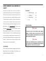
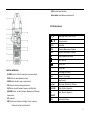
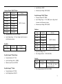
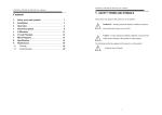
Dawson DCM201A Digital Clamp Meter Table of Contents User’s Manual LIMITED WARRANTY AND LIMITATION OF LIABILITY .............................................................3 Out of the Box ........................................................ 3 Safety Information ................................................. 3 Accessories ............................................................. 3 INTRODUCTION........................................................4 Preparation ............................................................ 4 Operations ............................................................. 4 Components and Buttons ....................................... 5 Symbols .............................................................. 5 Names of the Components................................. 5 Switches and Buttons ......................................... 6 LCD Display Features .......................................... 6 SPECIFICATIONS ......................................................... 7 1 1.3.1 General Specifications ................................... 7 Continuity ............................................................. 15 Technical Specifications .......................................... 7 Capacitance Measurement .................................. 15 USING THE METER ................................................. 10 Display Hold ......................................................... 10 MAINTENANCE ...................................................... 15 Manual Measurement ......................................... 10 General Maintenance .......................................... 15 Frequency and Duty Ratio .................................... 10 Battery Replacement............................................ 15 Setting MAX/MIN Recording ................................ 10 Test Leads Replacement ....................................... 16 REL/INRUSH Measurement .................................. 11 CONTACT DAWSON ................................................ 16 Backlight and clamp light..................................... 11 FEATURES ................................................... Back Page Auto Power Off ..................................................... 11 Measuring Preparations ...................................... 11 Current (AC/DC) Measurements........................... 12 Voltage (AC/DC) Measurements .......................... 12 Frequency and Duty ............................................. 13 Resistance Measurement ..................................... 14 Diodes Measurement ........................................... 14 2 LIMITED WARRANTY AND LIMITATION OF LIABILITY This instrument from Dawson Tools Inc. will be free from defects in Accessories workmanship and material for three years from the date of original purchase. 1000V 10A Test Leads 1pc This warranty does not cover defects resulting from damage caused by the User’s Manual 1pc user such as drops, neglect, misuse, unauthorized alteration, usage outside 6F22 9Volt Battery 1pc of specified conditions, contamination, or improper repair/maintenance. Case 1pc To receive service on the instrument if it becomes necessary during the warranty period, contact your nearest Dawson authorized service center at (800) 898-6991 or visit www.DawsonTools.com to obtain a return authorization (within the US only). A return authorization is necessary before returning any instrument to Dawson; no service will be provided without a return authorization. The user is responsible for properly packing the unit and charges such as shipping, freight and insurance charges. The Safety Information WARNING TO REDUCE THE RISK OF FIRE, ELECTRICAL SHOCK, PRODUCT DAMAGE OR PERSONAL INJURY, PLEASE FOLLOW THE SAFETY INSTRUCTIONS DESCRIBED IN THE USER MANUAL. READ THE USER MANUALS BEFORE USING THE METER. extent of Dawson's liability is limited solely to the repair/replacement of the instrument. The above warranty in its entirety is inclusive and no other warranties, written or oral, are expressed or implied. Out of the Box WARNING TO ENSURE SAFE OPERATION AND LIFE OF THE METER, DO NOT PLACE THE METER IN ANY ENVIRONMENT WITH HIGH PRESSURE, HIGH TEMPERATURE, DUST, EXPLOSIVE GAS OR VAPOR. Check the Meter and accessories thoroughly before using the Meter. Contact your local distributor if the Meter or any components are damaged or malfunction. 3 The DCM201A meter meets GB/T 13978-92 Digital Clamp Multimeter General technical requirements standard, GB4793.1-1995 (IEC-61010-1, IEC-61010-2-032) electronic measuring instrument safety standard,pollution 2 standard,with Over-Voltage categories of CAT IV 600 and CAT III 1000V. Preparations: Users must follow the standard safety instructions while using the meter: 1. Once the Meter is out of the package, check for any damage to the Meter before using. 2. Double check the Meter to make sure the components are in good condition. 3. Check the test leads before operation. Leads must be in good condition, check if leads are well covered by insulator; wires should not be exposed. 4. Use the original test leads included in the package for best performance and safety, if necessary, use the compatible leads with same specifications of the originals. Safety Symbols Important safety message Conforms to relevant European Union directives Warning Symbols WARNING Caution Risk of danger; Important information. See User’s Manual Statement identifies conditions and actions that failure to follow the instructions could result in false readings, damage the Tester or the equipment under test Operations: 1. Introduction 2. Overview 3. DCM201A is a portable, hand-held yet professional meter that features an LCD with backlight, overload protection and low battery indicator. These Meters are easy to use with one hand, 4. 5. suitable for professional users or amateurs, and ideal for school or home use. 6. Make sure to set the meter to the correct functions and measuring range. Do not use the Meter on a circuit where the measuring range is over the capable range specified in the User’s manual. Do not touch the tips of test leads when performing measurement. If the measurement is above 60V DC or 30V AC, make sure keeping hands below the tactile barrier and finger guards. Do not use the Meter on a circuit if the voltage is above 750V AC. In Manual Mode, if the circuit value is unknown, start the 4 7. 8. 9. 10. 11. 12. 13. Meter from maximum range and then adjust accordingly. Remove the leads from the circuit first before switching between functions. Do not power the circuit when measuring resistance, capacitance or diodes. Do not measure the capacitance before the capacitor is discharged. Do not operate the Meter near explosive gas, vapor or under dust. Stop the operation if the Meter or test leads appeared damaged or do not function properly. Unless the battery cover and the Meter case are firmly closed, do not use the Meter. Do not expose the Meter to direct sunlight, heat, or moisture. Components and Buttons Names of the Components 1. 2. 3. 4. 5. 6. 7. 8. 9. 10. 11. 12. 13. 14. Clamp Jaws:Measure Current Clamp Light Panel Clamp trigger Function Button (FUNC) Relative Button (REL) Frequency/Duty Ratio Button (Hz/%) LCD Display Common Input Terminals Resistance, Capacitance, Voltage, Frequency, Diodes and continuity Input Terminal Min Max Button(MAX/MIN) Display Hold / Back Light Button(B.L/ HOLD) Rotary Switch NCV Indicator Symbols Risk of danger. (Important information. See User’s Manual) May be used on hazardous live conductors. Double insulation(type II) CAT III Conforms to IEC-61010-1Over-Voltage categories III. standard Conforms to relevant European Union directives Earth ground 5 COM: Common Input Terminals Rotary Switch: switch between measurements LCD Display Features AC、DC 、 Alternating Current, Direct Current Diode, Continuity AUTO Auto Mode MAX Maximum Measurement Displayed MIN Minimum Measurement Displayed REL Relative Measurement Mode Auto Power Off Battery Low Switches and Buttons B.L/HOLD button: to hold the reading or to turn on backlight FUNC button: to switch between functions RANGE button: to switch range in manual mode REL button: for relative reading measurement Hz/% button: to switch between Frequency and Duty Ratio. MAX/MIN button: to switch between Maximum and Minimum measurement. OFF: power off INPUT: Resistance, Capacitance, Voltage, Current, Frequency, Diodes and continuity Input Terminal H Display Hold % Percentage (Duty Ratio) mV, V MilliVolt, Volt (Voltage) A Amp (Current) N,μF,mF Nanofarads, Microfarads, Millifarads Ω,kΩ, MΩ Ohms, Kilohms, Megaohms Hz kHz,MHZ Hertz, Kilohertz, Megahertz NCV Non-Contact Voltage 6 Specifications Technical Specifications The Meter should be calibrated annually between 18℃ ~ 28℃ and a relative humidity less than 75%. Temperature: 235℃ Relative Humidity: <75% 1.3.1 General Specifications Manual and Auto Mode Power Overload Protection Maximum Voltage Between Circuit and Ground: 1000V DC or 750V AC Maximum Working Height: 2000m Display: LCD Maximum Display Number: 5999 Auto Polarity Indication, ‘-’Indicates Negative Overload Indication: ‘0L’ Or ‘-0L’ Sampling Frequency: 3 Times / Sec Units Display: Display Functions and Units. Auto Power Off: 15 Minutes Input Power : 9V DC AC Current Low Battery Indication: LCD Display” ” Working Environment Temperature: 18℃ ~28℃ Storage Temperature:-10℃ ~50℃ Size:238×92×50mm Weight: ~420g (Include Battery) Resolution 60A 0.01A 600A 0.1A 1000A 1A Accuracy (2.5% + 8 Counts) Maximum Input Current: 1000A AC or 1000A DC Frequency Range @ 0~600A : 40 ~ 400Hz ; @ 600A~1000A : 40 ~60Hz DC Voltage Battery Type: 9V NEDA 1604, 6F22 Range Range Resolution 60mV 0.01mV 600mV 0.1mV 6V 0.001V 60V 0.01V 600 0.1V 1000V 1V Accuracy (0.5% + 5 Counts) (0.8% + 4 Counts) Input Resistance: 10M Maximum Input Voltage: 750V AC (RMS) or 1000V DC 7 Attention: During small voltage measurements, the Meter may display fluctuating readings when the test leads are not connected to the circuit. This is normal due to the high sensitivity of the Meter and will not affect the measurement. Frequency Frequency Through Clamp Measuring (A Mode) AC Voltage Range Resolution 60mV 0.01mV 600mV 0.1mV 6V 0.001V 60V 0.01V 600V 0.1V 750V 1V Accuracy (0.6% + 5 Counts) Range Resolution 99.99Hz 0.01Hz 999.9Hz 0.1Hz Accuracy (1.5% + 5 Counts) Measure Range: 10Hz ~ 1kHz Input Range: ≥ 20A AC (RMS) Input current should increase as circuit frequency increase Maximum Input Current: AC 1000A(RMS) Frequency Through “V” mode (0.8% + 4 Counts) Input Resistance: 10M Maximum Input Voltage: 750V AC (RMS) or 1000V DC Frequency Range: 40 ~ 400Hz Attention: During small voltage measurements, the Meter may display fluctuating readings when the test leads are not connected to the circuit. This is normal due to the high sensitivity of the Meter and will not affect the measurement. Range Resolution 99.99Hz 0.01Hz 999.9Hz 0.1Hz 9.999kHz 0.001kHz Accuracy (1.5% + 5 Counts) Range: 10Hz~ 10kHz Input Range: ≥ 20mV AC (RMS) Input voltage should increase as circuit frequency increase Input Resistance:10M Maximum Input Voltage:750V AC (RMS) 8 Frequency Through “HZ/DUTY” Mode Range Resolution 9.999Hz 0.001Hz 99.99Hz 0.01Hz 999.9Hz 0.1Hz 9.999kHz 0.001kHz 99.99KHZ 0.01kHZ 999.9KHZ 0.1KHZ 9.999MHZ 0.001MHZ Accuracy (0.3% + 5 Counts) Duty Ratio through “HZ/DUTY” Mode Frequency Response:10 ~10MHz Input Voltage Range: ≥ 2V AC (RMS) Input voltage should increase as circuit frequency increase Maximum Input Voltage: 250V AC (RMS) Resistance Overload Protection: 250V DC or AC (RMS) Input Voltage Range: ≥ 2V Input voltage should increase as circuit frequency increase 0.1 – 99.9% Resolution 0.1% Duty Ratio through “A” Mode (Clamp) Frequency Response: 10 ~ 1kHz Input Current Range: ≥20A AC(RMS) Maximum Input Current: AC 1000A Duty Ratio through “V” Mode Frequency Response: 10 ~10kHz Input Volatage Range: ≥ 60mV AC Range Resolution 600 0.1 Accuracy 6k 0.001k 60k 0.01k 600k 0.1k Accuracy 6M 0.001M (1.2% + 3 Counts) 0.3% 60M 0.1M (2.0% + 5 Counts) Duty Ratio Range Input Resistance: 10M Maximum Input Voltage: 750V AC (RMS) (0.8% + 3 Counts) Open Circuit Voltage: ~0.4V Over-voltage protection: 250V DC/AC (RMS) Continuity Function Resolution Description 0. 1 The Meter will beep if measure less than 50. Over-voltage protection: 250V DC or AC (RMS) 9 Using the Meter Capacitance Range Resolution 9.999nF 0.001nF 99.99nF 0.01nF 999.9nF 0.1nF 9.999F 0.001F 99.99F 0.01F 999.9F 0.1F 9.999mF 0.001mF 99.99mF 0.01mF Accuracy Display Hold During the measuring, press the “B.L./HOLD” button once to hold the reading, press again to release hold. (3.0% + 5 Counts) Manual Measurement When switching between positions on the rotary switct, the default range type is Auto. Press “RANGE” button to enter Over-voltage protection: 250V DC or AC (RMS) Manual mode. Each press increases the measuring range and will return to minimum range after maximum has been reached. Hold “RANGE” for 2 seconds to switch back to Auto mode. Diodes Symbol Resolution 0.001V Description Attention: Manual Measurement Mode is disabled when performing capacitance or frequency measurement. Display voltage reads Forward biased AC current: 1mA Backward AC Voltage: 3.3V Over-Voltage Protection: 250V DC or AC (RMS) Frequency and Duty Ratio When the Meter is on AC Voltage or AC Current Mode. Press “Hz/%” button once to measure the frequency of the circuit. Press “Hz/%” button again to measure the duty of the circuit. If the Meter is on HZ/DUTY mode, “Hz/%” button will switch between Hz and Duty. Press“Hz/%” button again to measure voltage or current 10 Attention: “Hz/%” is off when the Meter is measuring Max/Minimum of the circuit. Setting MAX/MIN Recording 1. Press “MAX/MIN” button once to measure the maximum, press “MAX/MIN” button again to measure the minimum, press “MAX/MIN” button a third time to show the difference between maximum and minimum. Press “MAX/MIN” button again to go back to maximum measurement, and repeat. 2. In Max/Min mode, measurement is saved automatically. 3. Press “MAX/MIN” button for 2 seconds to set the Meter back to normal measurement. Attention: The Meter is set to Manual mode when using Max/Min measurement. The Meter cannot perform Max/Min measurements when it is in Frequency/Duty Mode. Switching Between Functions When rotary switch is on Resistance, Diode, and continuity mode, press “FUNC” button to switch between those three. When rotary switch is on Voltage and Current mode, press “FUNC” button to switch between AC and DC. REL/INRUSH Measurement 1. Press “REL” button to enter relative measurement mode. When in this mode the current reading will be stored and the display shows the difference of the current reading and the stored reading; i.e. REL△(Output) = (current reading) – (reading when button is pressed) . 2. “REL” only performs in manual mode. Backlight and clamp light 1. Press “B.L/HOLD” button for 2 seconds to turn on display backlight, the backlight will stay on for 30 seconds before it is automatically turned off. 2. When backlight is on, hold “B.L/ HOLD” button for 2 seconds to manually turn off backlight. 3. In Current Mode, turning on backlight will also trigger the clamp light. Attention: The Meter uses an LED as a backlight; even though the light is set to auto off after 30 seconds, use only when needed to conserve the power. When battery voltage is less than 7.2V, the Meter will display “ ” to indicate low voltage. This “ ” may also appear when backlight is on. This is normal as backlight consume extra power, no battery change is necessary. (when “ ” is on, accuracy of reading is not guaranteed) Change the battery when “ ” is on without backlight is on. 11 Auto Power Off 1. When not in use, the Meter will automatically turn off after 15 minutes. The Meter will beep 5 times 1 minute before it turns off and a long beep right before it turns off. 2. After Auto Off, press any button to bring power back on. 3. To disable Auto Off, hold “FUNC” when turning on the Meter. Measuring Preparation Turn on the Meter by turning the rotary switch. If “ ” appears, replace the battery. “ ” indicates input voltage or current should not exceed the indicated value; this is to protect the Meter from damage. Turn the rotary switch to the proper position. When connecting to the circuit, connect COM input first before connecting to power. Remove the power lead first when disconnecting from the circuit. Current (AC/DC) Measurements WARNING TO AVOID ELECTRICAL SHOCK AND INJURY, PLEASE REMOVE TEST LEADS BEFORE MAKING CURRENT MEASUREMENTS. 1. Turn the rotary switch to AC current “A” 2. Choose “A 1000” range first if the target value is unknown. Adjust the range if necessary. 3. When measuring AC current, the measured wire should be properly seated within the clamp jaws and centered within the clamp. Also note that currents moving in different directions will cancel each other, so one wire must be measured at a time for a correct measurement. 4. Read the measurement on the LCD Display. Attention: Measure two or more wires together will cause false reading. The wire being measured should be centered within the clamp. “ ” indicates the maximum input AC Current is 1000 A。 For higher accuracy, when measuring DC current if Display shows none zero, press “REL” button to reset the reading to zero. Voltage (AC/DC) Measurements WARNING USE CAUTION WHEN MEASUREING HIGH VOLTAGE CIRCUITS TO AVOID ELECTRICAL SHOCK AND INJURY. DO NOT MEASURE INPUT VOLTAGES HIGHER THEN 750V AC. 1. Insert the black test leads into “COM” Input and red test lead into “INPUT” input, choose proper range. 2. Turn the rotary switch to or . This indicates DC voltage measurement; to measure AC voltage, press “FUNC” button once to enter AC Voltage measurement. 3. Connect the test leads to voltage source or load. 4. The Meter reading appears on the display. 12 Attention: When measuring low voltage sources, the reading will fluctuate on the display when the test leads are not connected to the circuit. This is normal due to the high sensitivity of the Meter. The Meter will display correct reading once the leads are connected to the circuit. In relative mode, auto measuring cannot be used. “ ”indicates the maximum input voltage is 750V AC or 1000V DC. In “mV” range, the maximum input voltage is 600mV DC or AC. The Meter will beep if the reading is greater than 750V RMS AC. Frequency and Duty Clamp Jaws Measurement (Current Mode) : WARNING REMOVE THE TEST LEADS FROM THE METER WHEN PERFORMING A CURRENT MEASUREMENT WITH THE CLAMP JAWS TO AVOID ELECTRICAL SHOCK AND INJURY. 1. Turn the rotary switch to “A” (current) mode. 2. Open the jaws by holding the trigger, place the wire in the jaws. 3. Press “Hz/%” button to measure frequency. 4. Read the measurement from the display. 5. Press “Hz/%” again to measure duty. Attention: Measuring two or more wires together will cause false readings. The accuracy of the reading is guaranteed between 10Hz ~ 1kHz. Below or above this range is still measurable, but the reading is not guaranteed. Duty range is10 ~ 95%. “ ”indicates the maximum input current is 1000A AC (RMS). Measuring in Voltage Mode: WARNING DO NOT MEASURE INPUTS OF MORE THAN 750V AC TO AVOID ELECTRICAL SHOCK AND INJURY. 1. Insert the black lead into “COM” input and the red lead into “INPUT” input. 2. Turn the rotary switch to or ,press “FUNC” button to enter AC Voltage mode. 3. Press “Hz/%” button to switch to frequency mode. 4. Connect the test leads to the voltage source or between loads. 5. Read the measurement from the display. 6. Press “Hz/%” button to switch to duty mode. Attention : The accuracy of reading is guaranteed between 10Hz ~ 10kHz. Below 10Hz a “00.0” will show, above 10kHz range is still measurable, but the reading is not guaranteed. Range of Duty is 10 ~ 95%. 13 “ ”indicates the maximum input voltage is 750V AC (RMS). Measuring in “HZ/DUTY” Mode: WARNING DO NOT MEASURE INPUTS OF MORE THAN 250V AC TO AVOID ELECTRICAL SHOCK AND INJURY. 1. Insert the black lead into “COM” input and the red lead into “INPUT” input. 2. Turn the rotary switch to “HZ”. 3. Connect the test leads to the voltage source or between loads. 4. Read the measurement from the display. 5. Press “Hz/%” button again to switch to duty mode. Attention: The accuracy of reading is guaranteed between 10Hz ~ 10kHz. Below 10Hz a “00.0” will show. Above 10kHz range is still measurable, but the reading is not guaranteed. Resistance Measurement WARNING AVOID ELECTRICAL SHOCK AND INJURY. POWER OFF THE CIRCUIT AND DISCHARGE THE CAPACITANCE BEFORE MEASURING THE RESISTANCE. 2. Turn the rotary switch to , this mode measures the resistance. 3. Connect the test leads across the circuit or resistors. 4. Read the measurement from the display. Attention: When the circuit is open, the Meter displays “OL”. The Meter will take several seconds to give a reading if the circuit has a resistance of more than 1MΩ. Diode Measurement 1. Insert the black lead into “COM” input and the red lead into “INPUT” input. 2. Turn the rotary switch to . 3. Press “FUNC” button twice to switch to Diode ( ) mode. 4. Connect the black lead to the cathode (-) and the red lead to the anode (+). 5. Read the measurement from the display. Attention: The Meter displays the forward biased value. If the diode is connected backwards or is an open circuit, the Meter will display “OL”. 1. Insert the black lead into “COM” input and the red lead into “INPUT” input. 14 Continuity WARNING AVOID ELECTRICAL SHOCK AND INJURY. POWER OFF THE CIRCUIT AND DISCHARGE THE CAPACITANCE BEFORE MEASURING THE CONTINUITY. 3. Place leads at the terminals of the capacitor after it is discharged. 4. Read off the measurement from the display. Attention: To improve the accuracy of measurements below 10nF, subtract 1. Insert the black lead into “COM” input and the red lead into “INPUT” input. 2. Turn the rotary switch to the distributed capacitance of the meter and cable. . 3. Press “FUNC” button to switch to continuity ( ) mode. 4. Connect leads to the circuit terminals. 5. The Meter will beep if the reading is below 50. 6. Read the measurement from the display. Maintenance General Maintenance To avoid possible electric shock or personal injury, repairs or servicing not covered in this manual should be performed only Attention: The Meter displays “OL” if the circuit is open or resistance is larger than 600. by qualified personnel. To avoid electrical shock, remove any input signals before cleaning. Capacitance Measurement WARNING AVOID ELECTRICAL SHOCK AND INJURY. DISCHARGE THE CAPACITOR BEFORE PERFORMING THE MEASURING. 1. Insert the black lead into “COM” input and the red lead into “INPUT” input. 2. Turn the rotary switch to . To avoid false readings that could lead to possible electric shock, replace the batteries as soon as the low battery indicator “ ” appears. Clean the instrument case with a damp cloth and mild detergent. Do not use aromatic hydrocarbons or chlorinated solvents for cleaning. 15 Turn the rotary switch to “OFF” and remove the test leads from the terminals when not used. Remove the battery if meter is not going to be used for long Attention: Double check the polarities of the battery. Test Leads Replacement WARNING REPLACE THE TEST LEADS WITH IDENTICAL OR COMPATIBLE LEADS. LEAD SPEC:1000V 10A. periods. Replace new leads if the current leads are worn. Battery Replacement WARNING REMOVE THE TEST LEADS FROM THE METER BEFORE REMOVING THE BATTERY CASE TO AVOID ELECTRICAL SHOCK AND INJURY. Contact Dawson Dawson Tools, Inc. 1142 S. Diamond Bar Blvd., #858 1. Replace new batteries if the Meter displays “ ”. 2. Loosen the battery compartment door screw and remove the door from the case bottom. 3. Remove and replace the battery. Diamond Bar, CA 91765 Phone: (310) 728-6220 www.DawsonTools,com Do not recycle 4. Reattach the battery compartment door to the case bottom and tighten the screw. 16 (Back Page) Features LCD Display Jaw Opening Auto Ranging Auto Power Off Relative Measurement Diode Test Continuity Buzzer MAX/MIN Data Hold Work Light Back Light Low Battery Indicator True RMS Non-Contact Voltage Detector 17