1
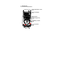
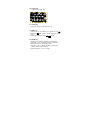
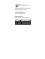
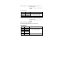
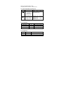
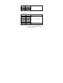
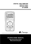
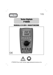
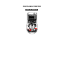
DIGITALMULTIMETER
USER’S MANUAL
C
C
CONTENTS
1. GENERAL INSTRUCTIONS…………………………… 1
2. DESCRIPTION ………………………………………… . 4
3. TECHNICAL SPECIFICATIONS ………………………. 7
4. OPERATING INSTRUCTION …………………………..13
5. MAINTENANCE ………………………………………….18
1. GENERAL INSTRUCTIONS
This multimeter has been designed according to IEC1010
concerning electronic measuring instruments with an
overvoltage category (CAT II 1000V, CAT III 600V) and
pollution 2.
To get the best service from this instrument, read carefully
this user's manual and respect the detailed safety
precautions.
1.1 Precautions safety measures
1.1.1 Preliminary
* When using this Multimeter, the user must observe all
normal safety rules concerning:
― protection against the dangers of electric current.
― protection of the Multimeter against misuse.
* For your own safety, only use the test probes supplied with
the instrument. Before use, check that they are in good
condition.
1.1.2 During use
* If the meter is used near noise generating equipment, be
aware that display may become unstable or indicate large
errors.
* Do not use the meter or test leads if they look damaged.
* Use the meter only as specified in this manual; otherwise,
the protection provided by the meter may be impaired.
* Use extreme caution when working around bare
conductors or bus bars.
* Do not operate the meter around explosive gas, vapor, or dust.
* Check the main function dial and make sure it is at the
correct position before each measurement.
* When the range of the value to be measured is unknown,
check that the range initially set on the multimeter is the
highest position.
* To avoid damages to the instrument, do not exceed the
maximum limits of the input values.
* Caution when working with voltages above 60Vdc or 30Vac
rms. Such voltages pose a shock hazard.
* When using the probes, keep your fingers behind the finger
guards.
* Before changing functions, disconnect the test leads from
the circuit under test.
* Disconnect circuits power and discharge all high-voltage
capacitors before testing resistance, continuity or diode.
* Before attempting to insert transistors for testing, always be
sure that test leads have been disconnected from any
measurement circuits.
* Components should not be connected to the hFE socket
when making voltage measurements with test leads.
* Before measuring current, turn off power to the circuit
before connecting the meter to the circuit.
* Change the battery when the
symbol appears to
avoid incorrect data.
1.1.3 Symbols:
Symbols used in this manual and on the instrument:
Caution: refer to the instruction manual. Incorrect use may
result in damage to the device or its components.
Earth
This instrument has double insulation.
Fuse: F 500mA/250V
1.1.4 Instructions
* Before opening up the instrument, always disconnect from
all sources of electric current and make sure you are not
charged with static electricity, which may destroy internal
components.
* Any adjustment, maintenance or repair work carried out on
the meter while it is live should be carried out only by
appropriately qualified personnel, after having taken into
account the instructions in this present manual.
* If any faults or abnormalities are observed, take the
instrument out of service and ensure that it can not be used
until it has been checked out.
* If the meter is not going to be used for a long time, take out
the battery and do not store the meter in high temperature
or high humidity environment.
* For continue protection against fire, replace fuse only with
the specified voltage and current rating: F500mA/250V.
* Never use the meter unless the back cover and battery
cover are in place and fastened fully.
2. DESCRIPTION
2.1 Instrument Familiarization
1 EF-DETECT Area
2 LCD display
3 Keypad
4 Back light key
C
5 Rotary switch
C
6 Terminals
2.2 LCD Display
3 3/4 digit, 18 mm high LCD.
2.3 ON/OFF key
¥ This key is used to turn the meter on or off
2.4 FUNC. key
¥ Selection of the dc (default) or ac mode and the
(default) or
mode: press on the key, the beep sounds
briefly.
¥ This key is operative in A and
( ) ranges.
2.5 RANGE key
¥ Selection of the automatic (default) or manual mode:
short press < 1 sec. on the key, the beep sounds briefly.
¥ Switch from manual to autoranging mode:
long press > 1 sec. on the key, the beep sounds briefly.
¥ In manual mode, ranges selection:
press successively < 1 sec. on the key.
¥ This key is operative in V and Ω ranges.
2.6 HOLD key
¥ Fixes the display on the current value and memories it
(short press).
¥ A second short press returns the meter to normal mode.
2.7 REL key
¥ Selection of the Relative measurement mode, press on the
key, the beep sounds briefly.
¥ This key is operative in V, A, Ω and CAP ranges.
2.8 Back light key
¥ This key is used to turn the back light on or off. Press the
key >2 sec. the backlight will be turned on. Press the key
again , the backlight will be turned off.
¥ the key is’t operative in
range.
2.9 Rotary switch
This switch is used to select functions and desired ranges .
There are different functions and 11 ranges provided.
2.10 Terminals
¥ VΩ
ΩHz℃
℃
: Terminal receiving the red lead for voltage,
resistance, capacitance, temperature, frequency, diode and
continuity measurements.
¥ COM:Terminal receiving the black lead as a common
reference.
¥ uAmA : Terminal receiving the red lead for uAmA
measurement..
¥ 10A : Terminal receiving the red lead for 10A
measurement.
3. TECHNICAL SPECIFICATIONS
3.1 General specifications
¥ Environment conditions:
600V CAT.III and 1000V CAT.Ⅱ
Pollution degree: 2
Altitude < 2000 m
Operating temperature:
0~40 OC, (<80% RH, non-condensing)
Storage temperature:
-10~60 OC, (<70% RH, battery removed)
¥ Temperature Coefficient:
0.1×(specified accuracy) / OC (<18 OC or >28 OC)
¥ MAX. Voltage between terminals and earth ground:
750V AC rms or 1000V DC
¥ Fuse Protection:
uAmA: F 500mA/250V ∅5×20
¥ Sample Rate: 3 times/sec for digital data.
¥ Display: 3 3/4 digits LCD display with max. reading 3999,
Automatic indication of functions and symbols.
¥ Range selection: automatic and manual.
¥ Over Range indication: LCD will display "OL".
¥ Low battery indication:
The "
" is displayed when the battery is under the proper
operation range.
¥ Polarity indication: "−" displayed automatically.
¥ Auto power off:
If there is no key or dial operation for 15 minutes, the meter
will power itself off to save battery consumption.
One minute before power off, the beeper will sound 5
sounds. The beeper will sound again before power off.
¥ Power source: 4.5V battery
¥ Dimensions: 156(L)×82(W)×29(H) mm.
¥ Weight: 220g. Approx. (battery included).
¥ Accessories: User's manual. Test leads. Carry case.
“K” type thermocouple
3.2 Measurement specifications
* Accuracy: ±(% of reading + number of digits) at 18OC to
28OC (64OF to 82OF) with relative humidity to 80%.
3.2.1 No contact AC Voltage detector
Sensitivity
Frequency
distance
>50V
50Hz
< 150mm
3.2.2 DC Voltage
Range
Resolution
Accuracy
400mV
0.1mV
±(0.8% of rdg +3 digits)
4V
1mV
40V
10mV
400V
100mV
1000V
1V
±(1.0% of rdg +3 digits)
Input impedance: 10MΩ
Maximum input voltage: 1000V dc or 750V ac rms.
3.2.3 AC Voltage
Range
Resolution
4V
1mV
40V
10mV
400V
100mV
Accuracy
±(1.0% of rdg +3 digits)
750V
1V
±(1.2% of rdg +3 digits)
Input impedance: 10MΩ
Maximum input voltage: 1000V dc or 750V ac rms.
Frequency Range: 40Hz-400Hz,
Response: Average, calibrated in rms of sine wave
3.2.4 DC Current
Range
Resolution
Accuracy
4000uA
1µA
400mA
0.1mA
±(1.2% of rdg +3 digits)
10A
10mA
±(2.0% of rdg +8digits)
Overload protection: F 500mA/250V fuse for uAmA range.
Maximum input current: 400mA dc or 400mA ac rms for µA
and mA ranges.
10A dc or 10A ac rms for 10A
ranges.
3.2.5 AC Current
Range
Resolution
Accuracy
4000uA
1µA
400mA
0.1mA
±(1.5% of rdg + 5 digits)
10A
10mA
±(3.0% of rdg + 8 digits)
Overload protection: F 500mA/250V fuse for uAmA range.
Maximum input current: 400mA dc or 400mA ac rms for µA
and mA ranges.
10A dc or 10A ac rms for 10A
ranges.
Frequency Range: 40Hz-400Hz,
Response: Average, calibrated in rms of sine wave
3.2.6 Resistance
Range
Resolution
400Ω
0.1Ω
4kΩ
1Ω
40kΩ
10Ω
400kΩ
100Ω
4MΩ
1kΩ
40MΩ
10kΩ
Accuracy
±(1.2% of rdg +3digits)
±(2.0% of rdg +5 digits)
Open circuit voltage: approx. 0.25V
Overload protection: 250V dc or 250V ac rms.
3.2.7 Diode and Audible continuity Test
Range
description
Test Condition
Open circuit voltage:
approximate 0.5V
Built-in buzzer
sounds if
resistance is less
than approx.40Ω
Forward DC Current:
approx. 1mA
Reversed DC Voltage:
approx. 1.5V
Display read
approx. forward
voltage of diode
Overload protection: 250V dc or 250V ac rms.
3.2.8 Temperature
Range
Resolution
Accuracy
-20℃ to 0℃
1℃
±(5% of rdg +4 digits)
0℃ to 400℃
1℃
±(1% of rdg +3 digits)
400℃ to 1000℃
1℃
±(2% of rdg +3 digits)
Overload protection: 250V dc or 250V ac rms.
3.2.9 Capacitance
Range
Resolution
Accuracy
4nF
1pF
±(5.0% of rdg +5 digits)
40nF
10pF
±(3.0% of rdg +5 digits)
400nF
100pF
4µF
1nF
40µF
10nF
200µF
100nF
Overload protection: 250V dc or 250V ac rms.。
3.2.10 Frequency
Range
Resolution
9.999Hz
0.001 Hz
99.99Hz
0.01 Hz
999.9Hz
0.1 Hz
9.999kHz
1Hz
99.99kHz
10Hz
199.9kHz
100Hz
Accuracy
±(0.1% of rdg +1 digit)
>200kHz
100Hz
Unspecified @ >200kHz
Overload protection: 250V dc or 250V ac rms.
Input Voltage range: 0.6V-3V ac rms (Input voltage must be
enlarged with increasing frequency
under measurement)
4. OPERATING INSTRUCTION
4.1 No contact AC Voltage detector
There is no auto power off function. And the
backlight is’t
operative in this range.
¥ Set rotary switch to the
range. Then the green LED
of the LED indicator is bright.
¥ Put the EF-DETECT AREA close to the lead or the power
socket , if AC electrical voltage is present , the red LED
indicator which in the top of the meter will flash and the
audible warning will sound,and the figure
will be
displayed on the LCD.
4.2 Voltage measurement
To avoid electrical shock and/or damage to the
instrument, do not attempt to take any voltage
measurement that might exceeds 1000Vdc or
750Vac rms. Do not apply more than 1000Vdc or
750Vac rms between the common terminal and
the earth ground.
¥ Set rotary switch to the V (ACV or DCV) range.
¥ Press "RANGE" key to select manual range
¥ Connect the black and red test leads to the COM and V
terminals respectively
¥ Connect the test leads to the circuit being measured
¥ Read the displayed value. The polarity of red test lead
connection will be indicated when making a DC
measurement.
4.3 Resistance measurement
To avoid electrical shock and/or damage to the
instrument,
disconnect
circuit
power
and
discharge all high-voltage capacitors before
measuring resistance.
¥ Set the rotary switch to Ω range.。
¥ Connect the black and red test leads to the COM and VΩ
terminals respectively.
¥ Connect the test leads to the circuit being measured and
read the displayed value.
¥ In order to ensure the best accuracy in measurement of
low resistance, short the test leads before measurement
and memory the test probe resistance in mind. This
necessary to subtract for the resistance of the test leads.
NOTE:
¥ For measuring resistance above 1MΩ, the meter may take
a few seconds to stabilize reading. This is normal for high
resistance measuring.
¥ When the input is not connected, i.e. at open circuit, the
figure "OL" will be displayed for the overrange condition.
4.4 Continuity measurement
To avoid electrical shock and/or damage to the
instrument, disconnect circuit power and
discharge all high-voltage capacitors before
testing for Continuity.。
¥ Set the rotary switch to
( ) range.
¥ Press "FUNC." key to select
measuring mode.
¥Connect the black and red test leads to the COM and Ω
terminals respectively.
¥ Connect the test leads to the resistance in the circuit being
measured.
¥ When the test lead to the circuit is below 40Ω, a continuous
beeping will indicate it.
Note: continuity test is available to check open/short of the
circuit.
4.5 Diode measurement
To avoid electrical shock and/or damage to the
instrument, disconnect circuit power and
discharge all high-voltage capacitors before
testing diodes.
¥ Set the rotary switch to
( ) range.
¥ Press "FUNC." key to select
measuring mode.
¥ Connect the black and red test leads to the COM and Ω
terminals respectively.
¥ Connect the red test lead to the anode, black test lead to
the cathode of the diode under testing.
¥ The meter will show the approx. forward voltage of the
diode. If the lead connection is reversed, only figure "OL"
displayed.
4.6 Capacitance measurement
To avoid electrical shock and/or damage to the
instrument, disconnect circuit power and
discharge all high-voltage capacitors before
measuring capacitance. Use the dc voltage
function to confirm that the capacitor is
discharged.
¥ Set the rotary switch to
range.
¥ Connect the black and red test leads to the COM and
terminals respectively.
¥ Connect the test leads to the capacitor being measured
and read the displayed value.
NOTE:
¥ The meter may take a few seconds (200µF range, 30
seconds) to stabilize reading. This is normal for high
capacitance measuring.
¥ To improve the accuracy of measurements less than 4nF,
subtract the residual capacitance of the meter and leads.
4.7 Frequency measurement
¥ Set the rotary switch to Hz range.
¥ Connect the black and red test leads to the COM and Hz
terminals respectively.
¥ Connect the test leads across the source or load under
measurement, and read the displayed value.
Note:
¥ Reading is possible at input voltages above 3V rms, but
the accuracy is not guaranteed.
¥ In noisy environment, it is preferable to use shield cable for
measuring small signal.
4.8 Temperature measurement
To avoid electrical shock, do not connect the
thermocouples with the electriferous circuit.
¥ Set the rotary switch to ℃ range. And the LCD display will
show the current environment temperature.
¥ Connect the red lead of“K” type thermocouple
into the ℃ jack and the black lead of“K”type
thermocouple into the “COM” jack.
¥ Contacting the object be measured with the
thermocouple probe.
¥ Read temperature value on the LCD display.
4.9 Current measurement
To avoid damage to the meter, check the meter's
fuse before proceeding. Use the proper terminals,
function, and range for your measurement.
¥ Set the rotary switch to the 4000µA, 400mA or 10A range.
¥ Press "FUNC." key to select DCA or ACA measuring mode.
¥ Connect the black test lead to the COM terminal and the
red test leads to the mA terminal for a maximum of 400mA.
For a maximum of 10A, move the red test lead to the 10A
terminal.
¥ Connect test leads in series with the load in which the
current is to be measured.
¥ Read the displayed value. The polarity of red test lead
connection will be indicated when making a DC
measurement.
¥ When only the figure "OL" displayed (Buzzer will sound
continually), it indicates overrange situation and the higher
range has to be selected.
4.10 Misplug Alarm
To avoid damage to the meter,the meter
provide “Misplug Alarm” function. When the
meter alarm , please check the range and the
terminal of the lead.
Following operation will bring alarm:
¥ Set the rotary switch to the any range expect A and
range , Connect the test lead to the uAmA or 10A terminal,
meter alarm.
¥ Set the rotary switch to the uA or mA range, Connect the
test lead to the 10A terminal, meter alarm.
¥ Set the rotary switch to the 10A range, Connect the
test lead to the uAmA terminal, meter alarm.
5. MAINTENANCE
5.1 General Maintenance
To avoid electrical shock or damage to the meter,
do not get water inside the case. Remove the test
leads and any input signals before opening the
case。
Periodically wipe the case with a damp cloth and mild
detergent. Do not use abrasives or solvents. Dirt or moisture
in the terminals can affect readings.
To clean the terminals:
¥ Turn the meter off and remove all test leads.
¥ Shake out any dirt that may be in the terminals.
¥ Soak a new swab with a cleaning and oiling agent (such as
WD-40).
¥ Work the swab around in each terminal. The oiling agent
insulates
the
terminals
from
moisture-related
contamination.
5.2 Fuse replacement
Before replacing the fuse, disconnect test leads
from any circuit under test.
To prevent damage or injury, replace the fuse only
with specified ratings.
¥ Set the meter to OFF state.
¥ Disconnect test leads from any inputs terminals.
¥ Use a screwdriver to unscrew the three screws secured on
the back cover and the battery cover , then unscrew the
two screws under the battery cover.
¥ Separate the back cover from the top case.
¥ Replace the fuse only with specified ratings:
F 500mA/250V ∅5×20.
¥ Replace the back cover and secure by the screws.
5.3 Battery replacement
Before replacing the battery, disconnect test
leads from any circuit under test, turn the meter
off and remove test leads from the input
terminals.
Use the following procedure:
¥ When the battery voltage drop below proper operation
range the
symbol will appear on the LCD display and
the battery need to be replaced.
¥ Set the meter to OFF state.
¥ Disconnect test leads from any inputs terminals.
¥ Use a screwdriver to unscrew the two screws secured on
the battery cover.
¥ Replace the battery with three new 1.5V batteries(AAA).
¥ Replace the battery cover by the two screws.