1
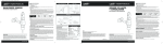
I N S TA L L AT I O N
B lac k I S O G rips f or 1 " bars
6340
CUSTOMER SERVICE
877.370.3604 (toll free)
PartS Included
1
1
2
1
1
4
1
1
1
2
1
1
4
2
1
Right (Throttle) Side Grip Assembly Including:
ISO Grip Out cage
Right Rubber Inserts
Chrome Accent Ring
End Cap
4-40 x 3/8” SHCS 18-8
Plastic Spacer Material
Left (Clutch) Side Grip Assembly Including:
ISO Grip Out cage
Left Rubber Inserts
Chrome Accent Ring
End Cap
4-40 x 3/8” SHCS 18-8
Tubes of Adhesive
Installation Instructions
INSTALLATION QUESTIONS
[email protected]
or call 715.247.2983
LIMITED WARRANTY
Küryakyn warrants that any Küryakyn products sold
hereunder, shall be free of defects in materials and
workmanship for a period of one (1) year from the
date of purchase by the consumer excepting the
following provisions:
• Küryakyn shall have no obligation in the event
the customer is unable to provide a receipt showing
the date the customer purchased the product(s).
• The product must be properly installed,
maintained and operated under normal conditions.
• Küryakyn makes no warranty, expressed or
implied, with respect to any gold plated products.
• Küryakyn shall not be liable for any consequential
and incidental damages, including labor and
paint, resulting from failure of a Küryakyn product,
failure to deliver, delay in delivery, delivery in
nonconforming condition, or for any breech of contract or duty between Küryakyn and a customer.
Please read and understand entire instructions before starting installation.
Thank you for choosing Küryakyn!
In order to protect you and others from possible injury
and/or property damage or loss, please pay close attention to all
instructions, warnings, cautions and attention notes regarding
the use and care of this product.
WARNING! THIS INDICATION ALERTS YOU TO THE FACT THAT IGNORING THE CONTENTS
DESCRIBED HEREIN CAN RESULT IN POTENTIAL DEATH OR SERIOUS INJURY.
CAUTION!
This indication alerts you to the fact that ignoring the contents described herein can
result in potential injury or material damage.
ATTENTION! This indication alerts you to the fact that ignoring the contents described herein may
negatively affect product performance and functionality.
Razor Blade, Sandpaper, Electrical Tape
Strictly observe the following guidelines in order to use the
product properly and avoid potentially dangerous accidents.
• Küryakyn makes no warranty of any kind in
regard to other manufacturer’s products distributed
by Küryakyn. Küryakyn will pass on all warranties
made by the manufacturer and where possible, will
expedite the claim on behalf of the customer,
but ultimately, responsibility for disposition of the
warranty claim lies with the manufacturer.
ABOUT OUR CATALOG
Be sure to ask your local dealer about other
Küryakyn ® products, the motorcycle parts and
accessories designed for riders by riders.
©2005 Küryakyn USA® All Rights reserved.
Procedure
STEP 1 Read and understand all steps in the instructions before starting the installation. Park the
motorcycle on a hard, level surface; turn off the ignition and allow the engine to cool.
IMPORTANT If your bike has an open end throttle sleeve you must be very careful not to get
glue between the sleeve and the bar. This will permanently glue the bar to the sleeve leaving it
inoperative.
6340-11MC-0910
• Küryakyn electrical products are warranted for
one (1) year from the date of purchase by the consumer. Components of Küryakyn products containing
L.E.D.s will be warranted for defects in materials and
workmanship for 3 years from the date of purchase.
You’ll find all our innovations for H-D, GL and
Metric Cruisers in our annual catalogs. Order
online today–select the ”CATALOGS” icon. Each
Küryakyn® product comes with a Proof-of-Purchase
good for a complimentary catalog.
Details in packaging.
Tools Suggested
The following instructions are written for closed ended throttle sleeves.
• Küryakyn products are often intended for use
in specific applications. Küryakyn makes no
warranty if a Küryakyn product is used in
applications other than intended.
-cont.-
STEP 2 Remove the existing grips from the handlebars. If unsure of procedure to remove grips, consult
the appropriate factory service manual. When cutting away the existing grips, be certain to not cut
through the throttle sleeve on the throttle side grip.
STEP 3 With sandpaper or emery cloth remove all grip and adhesive residue from both the throttle
PIC. 1
sleeve (right side) and exposed handlebar (left side). If your throttle sleeve has ribbed marks or other
protrusions, it will have to be sanded or ground smooth to allow the grip to slide into place. The
surface should be completely clean and slightly roughed from the sanding. With alcohol or similar
degreasing agent and a clean rag, wipe off the throttle sleeve and exposed handlebar.
STEP 4 Test fit each side. The throttle side grip has a slightly larger inside diameter than the clutch
side grip. The grips should slide into place with slight resistance. If the grips slide on too loosely,
make a “barber pole” wrap around the bar or throttle sleeve with electrical tape (PIC.1).
INSTALLATION OF CLUTCH SIDE GRIP
STEP 1 Some motorcycles have the switch housings “pinned” in place making it impossible to
relocate them. If the exposed handle bar on the clutch side is shorter than the length of the ISO-Grip,
the end rubber will not be fully supported once installed. Measure the length of exposed handlebar on
the clutch side. Measure the depth of the left grip. Subtract the length of the handlebar from the depth
of the grip; this will give you the length of the spacer required. Using a hack saw or utility knife, cut the
spacer to length and deburr. Insert the spacer into the grip and slide it down as far as possible with your
finger. Slide the grip onto the handlebar to push the spacer all the way to the end.
STEP 2 With the left side grip still in place, rotate the grip to determine the orientation that is most
comfortable. Make a mental note of the location or make a non-permanent mark on the grip and/or
switch housing. Remove the grip.
CAUTION! USE EXTREME CARE WHEN USING THE GLUE INCLUDED IN THIS KIT. READ ALL
PRECAUTIONS AND AVOID CONTACT WITH SKIN OR EYES. IT IS ALSO A GOOD IDEA TO COVER
ANY AREA OF THE BIKE WHERE GLUE COULD POSSIBLY DRIP DURING INSTALLATION.
STEP 3 With alcohol or similar degreasing agent and a clean rag, wipe off the exposed handlebar and
the inside of the grip to remove any contaminates. Take the supplied tube of adhesive and squeeze a
good amount of glue onto the throttle tube
IMPORTANT The adhesive supplied sets up ALMOST INSTANTLY in the absence of air. There is enough
time to slide the grip into place, but once it stops moving, it cannot be adjusted.
STEP 4 In one smooth motion, slide the grip onto the end of the bar all the way into position. Rotate
it back and forth slightly as you slide it on to help distribute the glue evenly and keep the grip from
“plowing” the glue up against the switch housing. Once in place, squeeze the grip firmly to press the
rubber against the bar and hold for 15 seconds.
INSTALLATION OF THROTTLE SIDE GRIP
STEP 1 Decide if you want the grip’s pads to match the clutch side when the bike is at rest or
underway with the throttle slightly opened. Without adhesive, slide the grip into place and determine
itsposition. Make a mental note of the location or make a non-permanent mark on the grip and/or
switchhousing.
STEP 2 Remove the grip and give it and the throttle sleeve a quick wipe to ensure they are free of
contaminates. Take the second supplied tube of adhesive and squeeze a good amount of glue onto the
throttle tube.
STEP 3 Slide the grip into place, rotating it clockwise as you slide it on to help distribute the glue
evenly and keep the grip from “plowing” glue up against the switch housing. Be prepared to quickly
wipe away any excess glue being “plowed” up by the grip that could be forced up against the switch
housing. Once in place, squeeze the grip firmly to press the rubber against the bar and hold for 15
seconds.
B lac k I S O G rips f or 1 " bars
Page
2
INSTALLATION