1
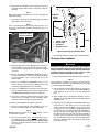
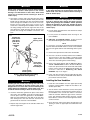
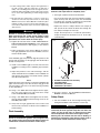
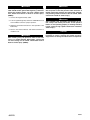
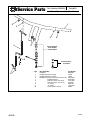
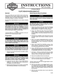
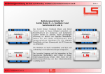
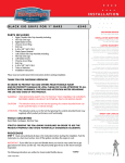
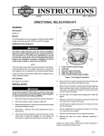
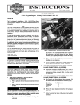
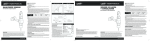
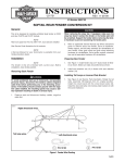
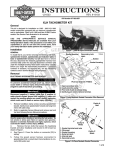
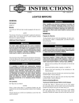
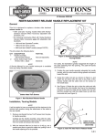
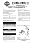
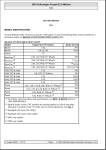
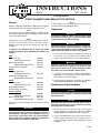
INSTRUCTIONS
®
REV. 8-04-03
-J02970
Kit Number 56369-03
STREET SLAMMER HANDLEBAR KIT FOR SOFTAILS
General
This kit is designed for installation on 2000 and later FX Softail
(except FXSTS), FLSTF and FLSTC model motorcycles.
NOTE
This kit does not fit with Heated Handgrips, Softail Nacelle Kit
part number 67907-96, Hydraulic Clutch Kits or Mini Tach Kits
on any of the above models.
NOTE
Installing this kit also requires installing new hand grips,
which are sold separately. Refer to the latest HarleyDavidson Parts and Accessories Catalog for a selection of
hand grips.
In addition to the Handlebar Kit, for each of the Softail
models listed below, these additional part numbers are
required:
FXST
Black clutch cable
OR Braided clutch cable
Black throttle/idle cable
OR Braided throttle/idle cable
Front directional mounting kit
FXSTB
Stock black clutch cable
OR Braided clutch cable
Stock black throttle/idle cable
OR Braided throttle/idle cable
38664-00
56414-03
56431-98
56345-03
68266-03
56411-03
56345-03
FXSTD
Black clutch cable
OR Braided clutch cable
Braided throttle/idle cable
Front directional mounting kit
38665-00
56411-03.
56392-03
68266-03.
FLSTF and FLSTC
Black clutch cable
OR Braided clutch cable
Black throttle/idle cable
OR Braided throttle/idle cable
38665-00
56411-03
56431-98
56345-03
See the Service Parts illustration for a list of items contained
in this kit.
1WARNING
A Service Manual is required to install this kit. The rider's
safety depends upon the correct installation of this kit. If
the procedure is not within your capabilities or you do
not have the correct tools, have any Harley-Davidson
dealer perform the installation. Improper installation of
this kit could result in death or serious injury.
NOTE
A Service Manual for your model motorcycle can be purchased from any Harley Davidson dealer.
Preparation
1WARNING
To prevent accidental vehicle start-up, which could
cause death or serious injury, disconnect battery cables
(negative cable first) before proceeding.
1WARNING
Disconnect negative (-) battery cable first. If positive (+)
cable should contact ground with negative (-) cable connected, the resulting sparks can cause a battery explosion,
which could result in death or serious injury. (00049a)
1. Refer to the Service Manual and follow the instructions
to remove the seat and disconnect the battery cables,
negative cable first. Retain all seat mounting hardware.
1WARNING
Gasoline is extremely flammable and highly explosive.
When servicing the fuel system, do not smoke or allow
open flame or sparks in the vicinity. Inadequate safety
precautions can result in death or serious injury.
2. Loosen the fuel tank. Refer to FUEL TANK-PARTIAL
REMOVAL in the appropriate section (Carbureted or
EFI Engine) of the Service Manual.
3. Bleed the brake fluid from the front brakes. See BLEEDING HYDRAULIC BRAKES in the Service Manual.
Removing the Stock Handlebar
CAUTION
Cover the front fender and the front of the fuel tank with
clean shop towels to prevent scratching. Damage to the
finish could result.
CAUTION
Damaged banjo bolt surfaces will leak when reassembled. Prevent damage to seating surfaces by carefully
removing brake line components.
1. Remove the brake line that runs from the front-brake
master cylinder to the front-brake caliper. See FRONT
BRAKE MASTER CYLINDER in the Service Manual.
2. Using a T27 TORX® drive head, remove the front-brake
master cylinder and clutch-lever assemblies (refer to
CLUTCH CABLE in the Service Manual) from the stock
handlebar.
1 of 6
3. Disconnect the handlebar control wiring from the gray
and black 6-place main harness connectors under the
fuel tank.
NOTE
When performing the following step, note left and right turn
signal wire routing.
4. See Figure 1. Separate the left and the right turn signal
Amp 2-place connector halves.
i04845C
1
3
All Models
Except
FXSTD
2
NOTE
Prior to performing the following step, make a note of connector pin socket location (number) with regard to wire color
of each pin.
i04802
4
Right Turn Signal
2-Place Connector
4
1
2
3
4
Clamp screw (4)
Upper clamp
Handlebar
Handlebar risers
FXSTD
Figure 2. Removing the handlebar cover
13. Bind the loose pin-terminal ends of each of the switchwire bundles and the turn signal wire bundles with tape.
Wiring the New Handlebar
Figure 1. Turn Signal 2-Place Amp Connector
5. Following instructions under Amp Electrical Connectors
in Service Manual, remove pins from right turn signal 2place connector. Repeat this step for the left turn signal
connector.
6. Refer to the RIGHT HANDLEBAR SWITCH section of
the Service Manual for removal of the right-side switch
housing assembly. This is necessary to access the
throttle cables.
7. Refer to the THROTTLE CONTROL section of the
Service Manual to disconnect the throttle cables from
the existing right grip/throttle sleeve assembly.
8. Using a T25 TORX drive head, remove the switch housings and attached wiring from the stock handlebar. Refer
to HANDLEBAR SWITCHES in the Service Manual.
9. See Figure 1. Remove and discard the four hex socket
head screws (1) holding the stock handlebar upper
clamp (2). Remove the upper clamp and discard.
10. Remove the handlebar (3) from the motorcycle.
11. Remove and discard the stock handlebar risers (4).
Save the remaining hardware for later installation.
NOTE
DO NOT remove the wires from the male Deutsch connectors behind the fuel tank.
12. Note the wire positions in the female Deutsch connectors leading from the switches. Refer to the wiring diagram and the DEUTSCH ELECTRICAL CONNECTORS
section in the Service Manual. Remove the wires from
the connectors.
-J02970
1WARNING
Grommets in each of the wiring holes in the handlebar
must be in position after routing the switch and turn signal
wiring through the handlebar. Switch operation without the
grommets in place may damage the wires, causing a short
circuit which could result in death or serious injury.
1. Remove the wiring retainers from both switch harnesses.
NOTE
The grommets installed in the next step will later be
maneuvered into position in the handlebar after the wiring
is routed through the handlebar.
2. See the Service Parts illustration. Slide one large grommet (2) onto each of the switch-wire bundles. Slide one
small grommet (3) onto each of the turn signal wire
pairs.
3. Apply a light spray of all-purpose lubricant, such as
WD-40®, to the right-side switch wire bundle and turn
signal wire pair.
4. Take two pieces of string that are approximately 3.5 feet
long and tie a small spare nut to one end of both
strings. Place the new handlebar so that the riser ends
are upward. Insert the nut with the strings attached into
the right side riser wiring hole and tip the handlebar so
that the nut slides out the right grip end of the handlebar. Remove the spare nut from the strings and with a
tweezers, fish one string out through the switch wiring
hole, and the other string out the turn signal wiring hole.
Ensure the opposite ends of the strings are still extending out the riser hole.
2 of 6
1WARNING
1WARNING
Wiring in the switch housings must be routed carefully
and exactly as shown. Pinch points in the switch
housings can short-circuit or sever wires, which could
cause loss of vehicle control resulting in death or
serious injury.
Avoid the pinch points shown in Figure 3. Pinch points
in the switch housings can short-circuit or sever wires,
which could cause loss of vehicle control resulting in
death or serious injury.
5. See Figure 3. Tie the end of the string from the switchwire hole to the switch-wire bundle. Gently feed the wire
bundle into the right-side wire hole and pull the bundle
down through the handlebar and out the riser hole.
Ensure the turn signal string stays in place as the
switch-wire is fed through the handlebar. Tie the end of
the string coming from the turn signal wire hole to the
turn signal wire. Gently feed the wire into the hole and
pull the wire through the handlebar and out the riser
hole.
1WARNING
Grommets in each of the wiring holes in the handlebar
must be in position after routing the switch and turn
signal wiring through the handlebar. Switch operation
without the grommets in place may damage the wires,
causing a short circuit which could result in death or
serious injury.
8. Loosely fasten the brake-lever and clutch-lever clamps
to the new handlebar.
9. Loosely fasten the handlebar-switch housings to the
new handlebar.
i04486a
Position the
inside switchedge pinch
point above
wires and
handlebar
hole
Upper switchhousing screw
10. ON FXST and FXSTD models, install the Front
Directional Mounting Kit part number 68266-03.
NOTE
It is necessary to install the Front Directional Mounting Kit
onto the FXST and FXSTD models to avoid contact between
the front turn signals and the fuel tank during vehicle operation.
11. Remove the tape from the ends of the wire bundles.
12. Check for electrical continuity between the handlebar
and each wire in the wire bundles. Continuity would
indicate a short circuit, which would require examination
of the wires and routing in the switch housing.
Keep wires
clear of pinch
points near
threaded post
Lower switchhousing screw
Figure 3. Switch-Housing wire routing
(Right-Side Housing Shown)
1WARNING
Carefully pull the control wires through the hole in the
riser of the handlebar to prevent stripping the wires.
Stripped wires can cause short circuits and damage the
vehicle electrical components, which could cause loss
of vehicle control resulting in death or serious injury.
6. Insert the switch-wire grommet into place in the switchwire hole in the handlebar. Insert the turn signal grommet into place in the turn signal hole in the handlebar.
Slide one large grommet (2) onto both of the wire bundles sticking out of the riser wire hole and insert the
grommet into the riser hole in the handlebar.
7. Repeat steps 3 through 6 for the left-side switch wires
and turn signal wires.
-J02970
13. Refer to the wiring diagram and the DEUTSCH ELECTRICAL CONNECTORS section in the Service Manual.
Insert each pin-connector from the left-side wire bundle
into the correct cavity of the GRAY female Deutsch pin
connector removed in Removing the Stock
Handlebar, step 12, on Page 2.
14. Insert each pin-connector from the right-side wire bundle into the correct cavity of the BLACK female Deutsch
pin connector removed earlier.
Installing the New Handlebar
1. Install the new handlebar onto the upper triple clamp
using the saved hardware. Torque the riser bolts to 2530 ft-lbs (34-41 Nm).
2. See the Service Parts Illustration. Connect the 6-place
Deutsch connectors coming from the bottom-center of
the handlebar to the correct main harness connectors
under the fuel tank. Match the gray harness connector
to the gray left-hand switch-control connector, and the
black harness connector to the black right-hand switchcontrol connector.
3. Route both turn signal wires down through large oval
opening in center of upper triple tree behind front riser
cover.
3 of 6
4. Follow routing noted in earlier step (left turn signal wires to
left side of frame; right turn signal wires to right side of
frame), route until wiring arrives near turn signal connector.
Install clips and/or wire guides saved in earlier step. Use wire
ties to secure turn signal wiring to switch wiring along the
route.
CAUTION
To avoid leakage, verify that the washers, banjo bolt,
brake line and caliper bore are completely clean.
1. See Figure 4 and the Service Parts illustration.
Use the stock banjo bolts and new brake-line gaskets
(items 6 and 7) from the kit to fasten the new braided
front brake line assembly (4) between the front-brake
master cylinder and the front-brake calipers.
5. On right side turn signal 2-place connector, follow notes
saved from removal step and instructions under Amp
Multilock Connectors in Service Manual to install two 2-place
terminals to Amp connector. Connect male and female connector halves. Repeat this step for the left turn signal wiring
and connector.
Replace the stock “P”-clamps with the new clamps (8
and 9) from the kit. Route the brake line through the
new clamps and adjust as necessary.
1WARNING
Gasoline is extremely flammable and highly explosive.
When servicing the fuel system, do not smoke or allow
open flame or sparks in the vicinity. Inadequate safety
precautions can result in death or serious injury.
Torque the banjo bolts to 17-20 ft-lbs (23-30 Nm).
Torque the brake line manifold screw to 10-15 ft-lbs
(13.6-20.3 Nm).
i04849
6. Tighten the fuel tank. Refer to FUEL TANK-INSTALLATION (AFTER PARTIAL REMOVAL) in the appropriate
section (Carbureted or EFI Engine) of the Service
Manual.
3
7. Follow instructions in the Service Manual to install a
new right grip/throttle sleeve to the handlebar, and connect the throttle cables.
3
NOTE
If the handlebar grips are patterned, align the pattern on the
left grip with the pattern on the right grip with the throttle in
the fully closed position.
1
8. Install a new handlebar grip on the left end of the new
handlebar according to the handlebar grip instruction
sheet.
2
9. Adjust the positions of the switch housings, and the
clutch and brake-lever assemblies on the handlebar for
rider posture and comfort. The brake master cylinder
must be horizontally level.
NOTE
Tighten the lower switch-housing screw before tightening the
upper switch-housing screw. This will leave any gap in the
switch housing at the front of the switch-housing assembly
for best appearance.
10. Using a T27 TORX drive head, tighten first the upper,
then the lower brake-lever and clutch-lever clamp
screws to 60-80 in-lbs (6.8-9.0 Nm).
11. Using a T25 TORX drive head, tighten first the lower,
then the upper handlebar-switch housing screws to 3545 in-lbs (4.0-5.1 Nm).
12. Verify that the right grip/throttle sleeve rotates and
returns freely and does not bind on the handlebar or
switch housing.
Final Assembly
1WARNING
Do not re-use brake-line gaskets. Use of original brakeline gaskets could cause front brake failure and loss of
control which could result in death or serious injury.
-J02970
2
4
1
2
3
4
Braided Front Brake Line Assembly
Stock Banjo Bolt
New Gasket (.44 inches)
New Gasket (.38 inches)
Figure 4. Front Braided Brake line Assembly
2. Bleed the brakes. See BLEEDING HYDRAULIC
BRAKES in the Service Manual.
Safety Check
1. Turn the handlebar to the left and right steering stops,
testing the handlebar control functions at each stop.
1WARNING
Clutch cables must not pull tight when handlebars are
turned fully to left or right fork stops. Be sure wires and
cables are clear of fork stops at steering head so they
will not be pinched when fork is turned against stops.
Steering must be smooth and free with no binding or
interference. Interference with steering could result in
loss of vehicle control and death or serious injury.
4 of 6
1WARNING
1WARNING
Connect positive (+) battery cable first. If positive (+)
cable should contact ground with negative (-) cable connected, the resulting sparks can cause a battery explosion, which could result in death or serious injury.
(00068a).
Prior to starting engine, verify that the throttle control
will snap back to the idle position when released. A
throttle control that prevents the engine from automatically returning to idle can lead to a loss of control, which
could result in death or serious injury.
2. Connect the negative battery cable.
3. Turn the Ignition/Light Key Switch to IGNITION and test
each handlebar switch for proper operation.
4. Apply the front brake hand lever to test operation of the
brake lamp.
5. Refer to the Service Manual, and follow instructions to
install the seat.
1WARNING
After installing seat, pull upward on front of seat to be
sure it is in locked position. While riding, a loose seat
can shift causing loss of control, which could result in
death or serious injury. (00070a)
-J02970
1WARNING
After completing this installation and bleeding the system, always test motorcycle brakes at low speed. If
brakes are not operating properly, or braking efficiency
is poor, testing at high speeds could result in death or
serious injury.
CAUTION
Carefully pull the wires through the hole in the riser of the
handlebar to prevent stripping the conduit and wires.
Stripped wires can damage the vehicle electrical components.
5 of 6
®
Service Parts
Part Number 56369-03
Date 8/03
Street Slammer Handlebar Kit
i04850a
1
2
3
7
3
4
2
2
Stock Hardware
for all models
except FXSTD
8
Stock Hardware
for FXSTD
6
-J02970
Item
1
2
3
4
5
6
7
8
9
10
Description/Qty.
Handlebar
Handlebar grommet, large (4)
Handlebar grommet, small (2)
Braided front brake line kit (contains items 5-10)
Braided brake line
Brake line gasket, .38” I.D.(2)
Brake line gasket, .44” I.D. (2)
“P”- clamp
“P”- clamp
Cable strap (not shown)
Part Number
56386-03
11386
11398
45264-98B
45265-98A
41731-88A
41733.88
68562-84
71795-63A
10065
6 of 6