1
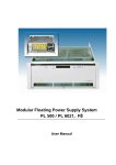
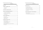
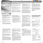
CAMAC Crate
+/-6V - +/-24V
User’s
and
Service- Manual
*00595.A0
Users Manual
CAMAC
W-Ie-Ne-R
Plein & Baus GmbH
General Remarks
The only purpose of this manual is a description of the product. It must not be
interpreted as a declaration of conformity for this product including the product and
software.
W-Ie-Ne-R revises this product and manual without notice. Differences of the
description in manual and product are possible.
W-Ie-Ne-R excludes completely any liability for loss of profits, loss of business,
loss of use or data, interrupt of business, or for indirect, special incidental, or
consequential damages of any kind, even if W-Ie-Ne-R has been advises of the
possibility of such damages arising from any defect or error in this manual or
product.
Any use of the product which may influence health of human beings requires the
express written permission of W-Ie-Ne-R.
Products mentioned in this manual are mentioned for identification purposes only.
Product names appearing in this manual may or may not be registered trademarks or
copyrights of their respective companies.
No part of this product, including the product and the software may be reproduced,
transmitted, transcribed, stored in a retrieval system, or translated into any language
in any form by any means with the express written permission of W-Ie-Ne-R.
January 13
i
*00595.A0
Users Manual
CAMAC
W-Ie-Ne-R
Plein & Baus GmbH
Table of contents:
1
2
General Information......................................................................................................... 1
1.1
-CAMAC bin ........................................................................................................... 1
1.2
Fan Tray................................................................................................................... 1
1.3
UEP 10 power supplies ............................................................................................ 2
Operation, Function and Control ..................................................................................... 3
2.1
Fan tray operation and control ................................................................................. 3
2.1.1
2.2
Function of fan tray switches and informations of the LED’s ................... 3
CAMAC Bin technical details ................................................................................. 4
2.2.1
CAMAC Bin UEC 01 Pin assignment PG 26 to power supply (PG27) .......... 4
2.2.2
Pin assignment PG 32 to fan tray (PG 31) ...................................................... 5
2.3
Power Supply UEP 10 ............................................................................................. 6
2.3.1
Regulator boards UEP 10................................................................................. 6
2.3.2
Monitoring and alarming signals ..................................................................... 7
2.3.3
Temperature sensors ........................................................................................ 7
2.3.4
Calibration of output voltage (UEP 10 ) .......................................................... 8
UEP 10 08 Has been not equipped with +/-12V outputs ......................................................... 8
APPENDIX A : Technical details UEP 10 08 ......................................................................... 8
APPENDIX B : Technical Documentation............................................................................ 10
January 13
ii
*00595.A0
Users Manual
CAMAC
W-Ie-Ne-R
Plein & Baus GmbH
1
General Information
All Wiener CAMAC Crates consist of a bin, a fan tray and a power supply. The
power supplies are linear regulated.
1.1
-CAMAC bin
The CAMAC-bin UEC 01 is a 7U CAMAC-crate for 25 CAMAC-modules
according to CERN-CAMAC-NOTE 46-04. The module connectors have been
centered by metal-guides, before touching the dataway plugs. Power supply plugged
in and locked from rear side, fan tray from front side.
Dimensions (whd): 483mm (=19″) x 310mm x 525mm (with power supply 570mm)
1.2
Fan Tray
The CAMAC Crate is equipped with an UEL 01 fan tray which gives the most
important monitoring information to the user.
The UEL 01 have three noise reduced 3 axial fans, which produce a maximum
airflow of 380m³/h static pressure.
Control panel with mains on/off, mains lamp, test sockets with LED’s for all 6
voltages and one for ground. All voltage bushes are overload protected by internal
resistors.
Buzzer alarm and LED’s for status bad, overload, overtemperature, whereas the
status LED is operated by suffix “M” power supplies only!
Weight 4 kg, approximately
UEL 01 unit can be operate in two different airflow modes. In the standard mode, the
air is taken from the front.
A bottom side air flow can be reached by removing the bottom plate and mounting
an optional front cover. The max. airflow is higher than 380m³/h and shows a good
homogeneity.
The maximal air flow reached in this mode As depicted in fig. 1 the maximum air
flow as well as the static pressure depends on the air resistance given by the plugged
in modules.
Note, that this maximum value may be diminished by empty, not covered slots.
January 13
1
*00595.A0
Users Manual
CAMAC
W-Ie-Ne-R
Plein & Baus GmbH
1.3
UEP 10 power supplies
The power supply is providing an additional 115 VAC output and fulfils the CERNStandard comprehensively.
UEP 10 is linear regulated. The DC- output stages have been outfitted with
foldback current characteristic in case of overcurrent.
A second circuit, overload, will protect the unit by activate the line breaker relay.
Primary the main transformer is protected be two 15A thermal circuit breaker,
situated below the mains input connector.
The UEP 10 is cooled by fan with horizontal air flow. Exhaust is through the 24V
heat sink (mains input side)
January 13
2
*00595.A0
Users Manual
CAMAC
W-Ie-Ne-R
Plein & Baus GmbH
2
Operation, Function and Control
2.1
Fan tray operation and control
2.1.1 Function of fan tray switches and informations of the LED’s
2.1.1.1
UEL 01
The UEL 01 fan tray is a simplified fan tray which conforms the CERN-Standard:
The front panel is equipped with the following facilities:
Switches:
POWER on/off
main switch for ventilation and power supply
LED indicators:
STATUS
green LED lights, if all voltages are within the limit*
OVERTEMPERATURE
yellow LED lights if overtemperature occurs
OVERLOAD
red LED lights, if an over current is detected.
AC POWER
main switch integrated
*In combination with M monitoring power supply
UEL 01 is not equipped with a fan fail circuit.
January 13
3
*00595.A0
Users Manual
W-Ie-Ne-R
CAMAC
Plein & Baus GmbH
2.2
CAMAC Bin technical details
2.2.1 CAMAC Bin UEC 01 Pin assignment PG 26 to power supply (PG27)
Function
PG 26
Function
PG 26
chassis ground
65
+6V return
43-44-45-46-70
220V phase switch
74
-6V
47-48-49-50-67
220V phase mains
75
-6V return
51-52-53-54-71
220V neutral switch
76
+12V
55
220V neutral mains
77
+12V return
56
117VAC neutral
78
-12V
57
117VAC phase
79
-12V return
58
+200V
80
+24V
59
+200V return
82
+24V return
60
power failure
1
-24V
62
overload warning
2
-24V return
63
overheat warning
3
0V monitor
5
buzzer warning
4
Y1 current
7
Y2 sensing
28
Y1 current return
8
Y2 sensing return
27
Y2 current
10
+6V sensing
29
Y2 current return
11
+6V sensing return
26
clean earth
64
-6V sensing
30
+6V current
12
-6V sensing return
27
+6V current return
13
+12V sensing
31
-6V current
14
+12V sensing return
26
-6V current return
15
-12V sensing
32
+12V current
16
-12V sensing return
27
+12V current return
17
+24V sensing
33
-12V current
18
+24V sensing return
26
-12V current return
20
-24V sensing
34
+24V current
21
-24V sensing return
27
+24V current return
22
January 13
4
*00595.A0
Users Manual
W-Ie-Ne-R
CAMAC
Plein & Baus GmbH
Y1
35
-24V current
23
Y1 return
36
-24V current return
24
Y2
37
Y1 sensing
25
Y2 return
38
Y1 sensing return
26
+6V
39-40-41-42-66
status warning
72
2.2.2 Pin assignment PG 32 to fan tray (PG 31)
Function
PG 32
Chassis ground
h
+12V current return
R
220V phase switch
AA
-12V current
S
220V phase mains
BB
-12V current return
T
220V neutral switch
CC
+24V current
U
220V neutral mains
DD
+24V current return
V
117V a.c. neutral
EE
-24V current
W
117V a.c. phase
FF
-24V current return
X
+200V
HH
+6V
a
overload warning
B
-6V
b
overheat warning
C
+12V
c
buzzer warning
D
-12V
d
+6V current
K
+24V
e
+6V current return
L
-24V
f
-6V current
M
0V voltage
monitoring
k
-6V current return
N
0V voltage warning
j
+12V current
P
status warning
A
January 13
5
*00595.A0
Users Manual
W-Ie-Ne-R
CAMAC
Plein & Baus GmbH
2.3
Power Supply UEP 10
2.3.1 Regulator boards UEP 10
The 4 control circuits for the ±6V, ±24V are of the similar design. Therefore the
+24V channel may be representative:
The power transistor T16 on the rear side heat sink are controlled by the amp U101,
RGL 03- followed by 2 driving transistors Q 101, Q102 connected to an auxiliary
voltage UH. Set point for the voltage control loop is derived from reference element
D108 biased sense and sense return lines, while the output DC level is measured
through the divider R119, R120 with voltage adjust pot R134.
Resistors R124 and R125 connect sense lines to the power path. In case of a failure
(example: broken lines) uncontrolled voltage levels are avoided.
All outputs are short circuit protected by means of an electric circuit providing a fold
back characteristic. This circuit works as follows:
The voltage drop across R110 is a value of output current. If this current increases
above a certain level, defined by pot R136, Q105 becomes non conducting. In
consequence Q104 begins to draw current from the voltage regulation loop an
transistor Q101, Q102 and further the output power transistors reduce the output
current. The output voltage of the power supply begins to drop. This drop reduces the
bias of Q105 and due to this feedback output voltage and current of the supply shift
along the fold back characteristic.
Voltage U
I short
I knee
Current I
This procedure comes to an end at output voltage U = (nearly) 0 and I = Ishort.
The parameters Iknee and Ishort may be adjusted at R136 and R135.
January 13
6
*00595.A0
Users Manual
CAMAC
W-Ie-Ne-R
Plein & Baus GmbH
Dual tracking:
For some applications of the power supply it is important that during turn on or turn
off transients opposite voltages have the same absolute value. This feature is
achieved by a small additional circuit: R117 and R 217 are of the same resistance.
Therefore the diode D103 clamps the bases of Q107 and Q207 to nearly ±0.35V and
both transistors are non conducting. Any nonsymmetrical output voltage shifts this
bias to nonsymmetrical levels, one transistor becomes conductive and acts on the
voltage control loop until both outputs are nearly symmetrical to the ground.
The total regulator circuit comprises 3 integrating control loops for:
output voltage
fold back characteristic
dual tracking
To avoid difficulties when servicing this circuit it is recommended to open jumper
B3. The regulator boards are enabled through U103/203 when the soft start relay in
HSP01 board has to be switched on (by 100Hz signal on UBW control board.)
2.3.2 Monitoring and alarming signals
In case of over temperature a yellow LED lights and a buzzer sounds; Mains are
switched off. In case of overload a red LED lights and a buzzer sounds.
2.3.3 Temperature sensors
All linear regulated power supplies are controlled with 4 independent temperature
sensors. Two are placed at the cooler heat sink, one is placed on the control board
and one sensor is inside the transformer. If one of this four sensors exceed the
maximum temperature-level, the temp. off function will interrupt the AC mains
circuit.
January 13
7
*00595.A0
Users Manual
W-Ie-Ne-R
CAMAC
Plein & Baus GmbH
2.3.4 Calibration of output voltage (UEP 10 )
front side of UEP 10
+24V (+12V) +6V
-24V
(-12V) -6V
(top view)
backside of UEP 10
UEP 10 08 Has been not equipped with +/-12V outputs
Voltages can be set by using the trim-pots on the top of the power supply
APPENDIX A: Technical details UEP 10 08
Linear regulated data UEP 10 (600W):
Input:
230V +10-15%, 48-63 Hz, inrush current limited to <15A,
mains filter, fuse protection
Derating:
600W output up to 42°C, with a derating of 2%/K up to 60°C
Noise and ripple:
full load < 0.6mV eff, <3mVpp, 1mV at 80% rated power
Regulation load:
10 to 100% Uout < 0.05%, line ±10%Uout < 0.02%
Recovery time:
load change 10% to 100% < 0.15 ms
Output impedance:
static < 0.2mOhm, dynamic at 100kHz < 0.3 Ohm
Temperature error:
< 5*10-5/K
Thermal protection: overheating protection by thermal sensors (4 fold),
Current limit:
adjusted to rated current
Characteristics:
short circuit protected by fold back characteristic, short circuit
current < 3A resp. 1A, reverse bias diodes.
January 13
8
*00595.A0
Users Manual
W-Ie-Ne-R
CAMAC
Plein & Baus GmbH
Voltage:
overvoltage protection (crow bar), ±6V, ±24V
calibrated at
±7.3V, ±28.5V
Options for power
supplies type M:
equipped with status-signal and status relay, rearming and
inhibit input, power-fail-signal, remote monitoring acc. to
CERN-CAMAC-note 46-04
Output voltages, currents and total power:
Outputs
+6V
-6V
+24V
UEP 10/88 45A
45A
8A
-24V 115 VAC
8A 0.5A
Note: The total Power consumption of the same polarity (+ or -) should not exceed
400W.
example:
January 13
+6V/45A=270W
+24V/8A=192W
+6V/40A=240W
+24V/4A= 96W
not allowed: Σ=462W
allowed: Σ=336W
9
*00595.A0
Users Manual
W-Ie-Ne-R
CAMAC
Plein & Baus GmbH
APPENDIX B: Technical Documentation, Drawings
Wiring Diagram UEP 10 M,
page 1
1406702
Wiring Diagram UEP 10 M / 55
page 2
1406702
Filter PCB CAP 2, Components
1218255
FAN Cooler
1218832
UEP 10 E00 BE
Main Transformer, Terminals UEP 10E17S
798282.B1
Regulator board RGL 03 E03, PCB
page1
1016563
Regulator board, connections
page 2
1016563
Regulator board, trim points
page 3
1016563
Regulator board, components
1004476.02.4
Aux power supply (HSP01) UEP1X/2X
1020269.B0
Aux power UEP1X/2X, components
1020269.B0
Control board UBW 05 E01 (simplified monitoring)
1110756.A5
Control board, components
1110756.A5
January 13
10
*00595.A0