1
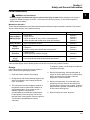
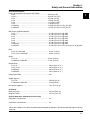
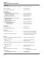
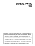
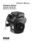
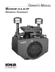
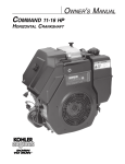
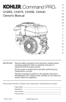
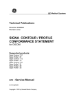
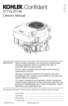
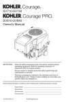
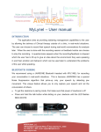
SERVICE MANUAL
COMMAND CV11-16,
CV460-465,
CV490-495
VERTICAL CRANKSHAFT
1
CV11-16
Section
1
CV460-465,
CV490-495
Safety and
General Information
Go Back
1
Section 1
Safety and General Information
Safety Precautions
To insure safe operations please read the following statements and understand their meaning. Also
refer to your equipment manufacturer's manual for other important safety information. This manual
contains safety precautions which are explained below. Please read carefully.
WARNING
Warning is used to indicate the presence of a hazard that can cause severe personal injury, death,
or substantial property damage if the warning is ignored.
CAUTION
Caution is used to indicate the presence of a hazard that will or can cause minor personal injury or
property damage if the caution is ignored.
NOTE
Note is used to notify people of installation, operation, or maintenance information that is important
but not hazard-related.
For Your Safety!
These precautions should be followed at all times. Failure to follow these precautions could result in
injury to yourself and others.
WARNING
WARNING
Accidental Starts can cause
severe injury or death.
Rotating Parts can cause severe
injury.
Disconnect and ground spark plug
leads before servicing.
Stay away while engine is in
operation.
Accidental Starts!
Disabling engine. Accidental
starting can cause severe injury
or death. Before working on the
engine or equipment, disable the
engine as follows: 1) Disconnect the
spark plug lead(s). 2) Disconnect
negative (-) battery cable from
battery.
Rotating Parts!
Keep hands, feet, hair, and
clothing away from all moving
parts to prevent injury. Never
operate the engine with covers,
shrouds, or guards removed.
WARNING
Hot Parts can cause severe burns.
Do not touch engine while operating
or just after stopping.
Hot Parts!
Engine components can get
extremely hot from operation. To
prevent severe burns, do not
touch these areas while the
engine is running—or immediately
after it is turned off. Never operate
the engine with heat shields or
guards removed.
1.1
Section 1
Safety and General Information
WARNING
WARNING
WARNING
Explosive Fuel can cause fires and
severe burns.
Carbon Monoxide can cause
severe nausea, fainting or death.
Explosive Gas can cause fires and
severe acid burns.
Stop engine before filling fuel tank.
Do not operate engine in closed or
confined area.
Charge battery only in a well
ventilated area. Keep sources of
ignition away.
Explosive Fuel!
Gasoline is extremely flammable
and its vapors can explode if
ignited. Store gasoline only in
approved containers, in well
ventilated, unoccupied buildings,
away from sparks or flames. Do not
fill the fuel tank while the engine is
hot or running, since spilled fuel
could ignite if it comes in contact
with hot parts or sparks from
ignition. Do not start the engine
near spilled fuel. Never use
gasoline as a cleaning agent.
WARNING
Lethal Exhaust Gases!
Engine exhaust gases contain
poisonous carbon monoxide.
Carbon monoxide is odorless,
colorless, and can cause death if
inhaled. Avoid inhaling exhaust
fumes, and never run the engine
in a closed building or confined
area.
WARNING
Uncoiling Spring can cause severe
injury.
Wear safety goggles or face
protection when servicing retractable
starter.
Cleaning Solvents can cause
severe injury or death.
Use only in well ventilated areas
away from ignition sources.
Flammable Solvents!
Carburetor cleaners and solvents
are extremely flammable. Keep
sparks, flames, and other sources
of ignition away from the area.
Follow the cleaner manufacturer’s
warnings and instructions on its
proper and safe use. Never use
gasoline as a cleaning agent.
1.2
Spring Under Tension!
Retractable starters contain a
powerful, recoil spring that is under
tension. Always wear safety
goggles when servicing retractable
starters and carefully follow
instructions in "Retractable Starter"
Section 7 for relieving spring
tension.
Explosive Gas!
Batteries produce explosive
hydrogen gas while being
charged. To prevent a fire or
explosion, charge batteries only in
well ventilated areas. Keep
sparks, open flames, and other
sources of ignition away from the
battery at all times. Keep batteries
out of the reach of children.
Remove all jewelry when servicing
batteries.
Before disconnecting the negative
(-) ground cable, make sure all
switches are OFF. If ON, a spark
will occur at the ground cable
terminal which could cause an
explosion if hydrogen gas or
gasoline vapors are present.
CAUTION
Electrical Shock can cause injury.
Do not touch wires while engine is
running.
Electrical Shock!
Never touch electrical wires or
components while the engine is
running. They can be sources of
electrical shock.
Section 1
Safety and General Information
Engine Identification Numbers
When ordering parts, or in any communication
involving an engine, always give the Model,
Specification, and Serial Numbers of the engine.
1
The engine identification numbers appear a on decal
(or decals) affixed to the engine shrouding. See Figure
1-1. An explanation of these numbers is shown in
Figure 1-2.
Identification Decal
Figure 1-1. Engine Identification Decal Location.
A. Model No.
Command Engine
Vertical Crankshaft
Displacement (cc)
460 = 460 cc
490 = 490 cc
B. Spec. No.
Engine Model Code
Code
Model
11
CV11
12
CV12.5
22
CV13
14
CV14
41
CV15
43
CV16
265
CV460-465
275
CV490-495
C. Serial No.
C V 12.5 ST
Version Code
S = Electric Start
T = Retractable Start
ST = Electric/Retractable Start
Horsepower
11 = 11 HP
12.5 = 12.5 HP
13 = 13 HP
14 = 14 HP
15 = 15 HP
16 = 16 HP
or
1203
Variation of
Basic Engine
MODEL NO. CV12.5ST
SPEC. NO. 1203
SERIAL NO.2105810334
A
B
C
REFER TO OWNER'S MANUAL FOR
SAFETY, MAINTENANCE SPECS
AND ADJUSTMENTS. FOR SALES
AND SERVICE IN US/CANADA
CALL: 1-800-544-2444.
www.kohlerengines.com
2105810334
KOHLER CO. KOHLER, WI USA
Year Manufactured Code
Factory Code
Code
Model
21
1991
22
1992
23
1993
24
1994
25
1995
26
1996
27
1997
28
1998
29
1999
30
2000
31
2001
32
2002
Figure 1-2. Explanation of Engine Identification Numbers.
1.3
Section 1
Safety and General Information
Oil Recommendations
Using the proper type and weight of oil in the
crankcase is extremely important, as is checking oil
daily, and changing oil regularly. Failure to use the
correct oil, or using dirty oil, causes premature engine
wear and failure. Synthetic oil is recommended for
use in LPG-fueled engines because there is less
oxidation or thickening, and deposit accumulation on
intake valves is substantially reduced.
Oil Type
Use high-quality detergent oil of API (American
Petroleum Institute) service class SG, SH, SJ or
higher. Select the viscosity based on the air
temperature at the time of operation as shown below.
**
*
Fuel Recommendations
WARNING: Explosive Fuel!
Gasoline is extremely flammable and its vapors can
explode if ignited. Store gasoline only in approved
containers, in well ventilated, unoccupied buildings,
away from sparks or flames. Do not fill the fuel tank
while the engine is hot or running, since spilled fuel
could ignite if it comes in contact with hot parts or
sparks from ignition. Do not start the engine near
spilled fuel. Never use gasoline as a cleaning agent.
General Recommendations
Purchase gasoline in small quantities and store in
clean, approved containers. A container with a capacity
of 2 gallons or less with a pouring spout is
recommended. Such a container is easier to handle
and helps eliminate spillage during refueling.
Do not use gasoline left over from the previous
season, to minimize gum deposits in your fuel system
and to insure easy starting.
Do not add oil to the gasoline.
*Use of synthetic oil having 5W-20 or 5W-30 rating is
acceptable, up to 4°C (40°F).
**Synthetic oils will provide better starting in extreme cold
below -23°C (-10°F).
NOTE: Using other than service class SG, SH, SJ or
higher oil, or extending oil change intervals
longer than recommended, can cause engine
damage.
A logo or symbol on oil containers identifies the API
service class and SAE viscosity grade. See Figure 1-3.
Do not overfill the fuel tank. Leave room for the fuel to
expand.
Fuel Type
For best results, use only clean, fresh, unleaded
gasoline with a pump sticker octane rating of 87 or
higher. In countries using the Research method, it
should be 90 octane minimum.
Unleaded gasoline is recommended, as it leaves less
combustion chamber deposits. Leaded gasoline may
be used in areas where unleaded is not available and
exhaust emissions are not regulated. Be aware
however, that the cylinder head will require more
frequent service.
Gasoline/Alcohol blends
Gasohol (up to 10% ethyl alcohol, 90% unleaded
gasoline by volume) is approved as a fuel for Kohler
engines. Other gasoline/alcohol blends are not
approved.
Figure 1-3. Oil Container Logo.
Refer to Section 6 - “Lubrication System” for detailed
oil check, oil change, and oil filter change procedures.
1.4
Gasoline/Ether blends
Methyl Tertiary Butyl Ether (MTBE) and unleaded
gasoline blends (up to maximum of 15% MTBE by
volume) are approved as a fuel for Kohler engines.
Other gasoline/ether blends are not approved.
Section 1
Safety and General Information
Periodic Maintenance
1
WARNING: Accidental Starts!
Disabling engine. Accidental starting can cause severe injury or death. Before working on the engine or
equipment, disable the engine as follows: 1) Disconnect the spark plug lead(s). 2) Disconnect negative (-)
battery cable from battery.
Maintenance Schedule
These required maintenance procedures should be performed at the frequency stated in the table. They should
also be included as part of any seasonal tune-up.
Maintenance Required
Frequency
Fill fuel tank.
Check oil level.
Check air cleaner for dirty1, loose, or damaged parts.
Check air intake and cooling areas, clean as necessary1.
Refer to:
Daily or Before
Starting Engine
•
•
•
•
Every 25 Hours
• Service precleaner element1.
Section 5
Section 6
Section 4
Section 4
Section 4
Every
100 Hours
• Replace air cleaner element1.
• Change oil1.
• Remove cooling shrouds and clean cooling areas1.
Section 4
Section 6
Section 4
Every
200 Hours
• Change oil filter1.
• Check spark plug condition and gap.
Section 6
Section 8
Annually or
• Have bendix starter drive serviced2.
Section 8
Every
• Have solenoid shift starter disassembled and cleaned2.
Section 8
500 Hours
1
Perform these maintenance procedures more frequently under extremely dusty, dirty conditions.
2
Have a Kohler Engine Service Dealer perform this service. Not necessary on Delco Starters.
Storage
If the engine will be out of service for two months or
more, use the following storage procedure.
1. Clean the exterior surfaces of the engine.
2. Change the oil and oil filter while the engine is still
warm from operation. See “Change Oil and Oil
Filter” in Section 6.
3. The fuel system must be completely emptied, or
the gasoline must be treated with a stabilizer to
prevent deterioration. If you choose to use a
stabilizer, follow the manufacturers
recommendations, and add the correct amount
for the capacity of the fuel system. Fill the fuel
tank with clean, fresh gasoline. Run the engine for
2-3 minutes to get stabilized fuel into the
carburetor.
To empty the system, run the engine until the tank
and system are empty.
4. Remove the spark plug. Add one tablespoon of
engine oil into the spark plug hole. Install the plug,
but do not connect the plug lead. Crank the
engine two or three revolutions.
5. Remove the spark plug. Cover the spark plug
hole with your thumb, and turn the engine over
until the piston is at the top of its stroke. (Pressure
against thumb is greatest.) Reinstall the plug, but
do not connect the plug lead.
6. Store the engine in a clean, dry place.
1.5
Section 1
Safety and General Information
Air Filter
and Cover
CL Cylinder
Oil Filter
Carburetor
Fuel Shut-off
Solenoid
47
(1.85)
Carburetor
Fuel Inlet
Engine Mounting
Surface
Oil Drain Plug
3/8 NPT Inch
17
(.67)
262
(10.31)
CL Cylinder
Oil Filter Side
24.0
(9.4)
25.4
(1.00)
Valve Cover End
411
(16.18)
Air Cleaner
Cover Removal
6.34 Keyway Width
(.250)
296
(11.65)
321
(12.64)
CL Cylinder
137.5
(5.41)
Exhaust Flange
Mounting Surface
Engine Mounting
Surface
25.4
(1.00)
Starter Motor
26.5
(1.04)
62.5
(2.46)
6.34
Keyway Width
(.250)
Starter Side
CL Throttle Cable
19
(.74)
207
(80.16)
204
(8.04)
176.6
(6.95)
372
(14.66)
45°
CL Cylinder
124
(4.88)
220.2
(8.67)
45°
60.0
(2.36)
4xM8x1.25
254
(10.0)
CL Cylinder
135.0
(5.31)
Oil Level
Dipstick & Fill
108
(4.25)
4.0
(.16)
328*
(12.91)
463*
(18.23)
Rotation
40°
Flywheel End
*CV11-16 10 mm shorter
M8x1.25
2 Studs
35°
35°
Exhaust Flange
Mounting Surface
Engine Mounting Surface
Dimensions in () are inch equivalents.
Figure 1-4. Typical Engine Dimensions.
1.6
Section 1
Safety and General Information
General Specifications¹
Power (@ 3600 RPM, corrected to SAE J1995)
CV11 ............................................................................... 8.2 kW (11 HP)
CV12.5 ............................................................................ 9.33 kW (12.5 HP)
CV13 ............................................................................... 9.75 kW (13 HP)
CV14 ............................................................................... 10.5 kW (14 HP)
CV15 ............................................................................... 11.19 kW (15 HP)
CV16 ............................................................................... 11.9 kW (16 HP)
CV460-465 ...................................................................... 11.9 kW (16 HP)-13.0 kW (16.5 HP)
CV490-495 ...................................................................... 12.7 kW (17 HP)-13.4 kW (18 HP)
Max Torque (@ RPM indicated)
CV11 ................................................................................
CV12.5 .............................................................................
CV13 ................................................................................
CV14 ................................................................................
CV15 ................................................................................
CV16 ................................................................................
CV460-465 .......................................................................
CV490-495 .......................................................................
1
27.4 N·m (20.2 ft. lb.) @ 2000
27.8 N·m (20.5 ft. lb.) @ 2500
27.8 N·m (20.5 ft. lb.) @ 2500
28.9 N·m (21.3 ft. lb.) @ 2500
33.2 N·m (24.5 ft. lb.) @ 2400
35.3 N·m (26.0 ft. lb.) @ 2400
36.3 N·m (26.8 ft. lb.) @ 2400
37.8 N·m (27.9 ft. lb.)-38.1 N·m (28.1 ft. lb.) @ 2400
Bore
CV11-14, CV460-465 ........................................................ 87 mm (3.43 in.)
CV15, CV16, CV490-495 .................................................. 90 mm (3.60 in.)
Stroke
CV11-16 .......................................................................... 67 mm (2.64 in.)
CV460-465, CV490-495 .................................................. 77 mm (3.03 in.)
Displacement
CV11-14 ............................................................................ 398 cc (24.3 cu. in.3)
CV15, CV16 ...................................................................... 426 cc (26.0 cu. in.3)
CV460-465 ........................................................................ 460 cc (27.9 cu. in.3)
CV490-495 ........................................................................ 490 cc (29.9 cu. in.3)
Compression Ratio .................................................................. 8.5:1
Weight (approx.)
CV11-16 ............................................................................ 39.54 kg (87 lb.)
CV460-465, CV490-495 .................................................... 41.9 kg (90 lb.)
Oil Capacity (approx.) .............................................................. 1.9 L (2.0 U.S. qt.)
Air Cleaner
Base Nut Torque ...................................................................... 9.9 N·m (88 in. lb.)
Wing Nut Torque ...................................................................... 1.5 N·m (12 in. lb.)
Angle of Operation - Maximum (at full oil level)
Intermittent - All Directions ....................................................... 35°
Continuous - All Directions ....................................................... 20°
1
Values are in Metric units. Values in parentheses are English equivalents. Lubricate threads with engine oil prior to
assembly.
1.7
Section 1
Safety and General Information
Balance Shaft
End Play ...................................................................................................... 0.0575/0.3625 mm (0.0027/0.0137 in.)
Running Clearance ...................................................................................... 0.0250/0.1520 mm (0.0009/0.0059 in.)
Bore I.D.
New ....................................................................................................... 20.000/20.025 mm (0.7874/0.7884 in.)
Max. Wear Limit .................................................................................... 20.038 mm (0.7889 in.)
Balance Shaft Bearing Surface O.D.
New ....................................................................................................... 19.962/19.975 mm (0.7859/0.7864 in.)
Max. Wear Limit .................................................................................... 19.959 mm (0.7858 in.)
Camshaft
End Play (free) ............................................................................................. 0.088/0.393 mm (0.003/0.015 in.)
End Play (with shims) .................................................................................. 0.076/0.127 mm (0.003/0.005 in.)
Running Clearance ...................................................................................... 0.025/0.105 mm (0.0010/0.0041 in.)
Bore I.D.
New ....................................................................................................... 20.000/20.025 mm (0.7874/0.7884 in.)
Max. Wear Limit .................................................................................... 20.038 mm (0.7889 in.)
Camshaft Bearing Surface O.D.
New ...................................................................................................... 19.962/19.975 mm (0.7859/0.7864 in.)
Max. Wear Limit ................................................................................... 19.959 mm (0.7858 in.)
Carburetor
Preliminary Low Idle Fuel Needle Setting ................................................... 1 Turn
Fuel Bowl Retaining Screw Torque ............................................................. 5.1-6.2 N·m (45-55 in. lb.)
Connecting Rod
Cap Fastener Torque (torque in increments)
6 mm straight shank bolt ....................................................................... 11.3 N·m (100 in. lb.)
8 mm step-down bolt ............................................................................. 14.7 N·m (130 in. lb.)
8 mm straight shank bolt ....................................................................... 22.7 N·m (200 in. lb.)
Connecting Rod-to-Crankpin Running Clearance at 21°C (70°F)
New ....................................................................................................... 0.030/0.055 mm (0.0012/0.0022 in.)
Max. Wear Limit .................................................................................... 0.07 mm (0.0025 in.)
Connecting Rod-to-Crankpin Side Clearance .............................................. 0.18/0.41 mm (0.007/0.016 in.)
Connecting Rod-to-Piston Pin Running Clearance at 21°C (70°F) .............. 0.015/0.028 mm (0.0006/0.0011 in.)
Piston Pin End I.D.
New ...................................................................................................... 19.015/19.023 mm (0.7486/0.7489 in.)
Max. Wear Limit ................................................................................... 19.036 mm (0.7495 in.)
Crankcase
Governor Cross Shaft Bore I.D.
New ...................................................................................................... 6.025/6.050 mm (0.2372/0.2382 in.)
Max. Wear Limit ................................................................................... 6.063 mm (0.2387 in.)
1.8
Section 1
Safety and General Information
Crankshaft
End Play (free) ........................................................................................ 0.0575/0.4925 mm (0.0022/0.0193 in.)
End Play (thrust bearing with shims) ...................................................... 0.050/0.530 mm (0.0020/0.0209 in.)
1
Crankshaft Bore in Crankcase I.D.
New .................................................................................................. 44.965/44.990 mm (1.7702/1.7712 in.)
Max. Wear Limit ............................................................................... 44.9758/45.0012 mm (1.7707/1.7717 in.)
Crankshaft Bore in Crankcase Running Clearance
New .................................................................................................. 0.0300/0.0770 mm (0.0011/0.0030 in.)
Crankshaft Bore in Oil Pan I.D.
New .................................................................................................. 41.965/42.003 mm (1.6521/1.6536 in.)
Max. Wear Limit ............................................................................... 41.9760/42.0141 mm (1.6526/1.6541 in.)
Crankshaft Bore in Oil Pan Running Clearance
New .................................................................................................. 0.0300/0.0880 mm (0.0011/0.0034 in.)
Flywheel End Main Bearing Journal
O.D. - New .......................................................................................
O.D. - Max. Wear Limit ....................................................................
Max. Taper .......................................................................................
Max. Out-of-Round ..........................................................................
44.913/44.935 mm (1.7682/1.7691 in.)
44.84 mm (1.765 in.)
0.022 mm (0.0009 in.)
0.025 mm (0.0010 in.)
Oil Pan End Main Bearing Journal
O.D. - New .......................................................................................
O.D. - Max. Wear Limit ....................................................................
Max. Taper .......................................................................................
Max. Out-of-Round ..........................................................................
41.915/41.935 mm (1.6502/1.6510 in.)
41.86 mm (1.648 in.)
0.020 mm (0.0008 in.)
0.025 mm (0.0010 in.)
Connecting Rod Journal
O.D. - New .......................................................................................
O.D. - Max. Wear Limit ....................................................................
Max. Taper .......................................................................................
Max. Out-of-Round ..........................................................................
38.958/30.970 mm (1.5338/1.5343 in.)
38.94 mm (1.5328 in.)
0.012 mm (0.0005 in.)
0.025 mm (0.0010 in.)
Crankshaft T.I.R.
PTO End, Crank in Engine ............................................................... 0.30 mm (0.012 in.)
Entire Crank, in V-Blocks ................................................................. 0.10 mm (0.0039 in.)
Cylinder Bore
Cylinder Bore I.D.
New
CV11-14, CV460-465 .....................................................................
CV15, CV16, CV490-495 ...............................................................
Max. Wear Limit
CV11-14, CV460-465 .....................................................................
CV15, CV16, CV490-495 ...............................................................
Max. Out-of-Round ..........................................................................
Max. Taper .......................................................................................
87.000/87.025 mm (3.4252/3.4262 in.)
90.000/90.025 mm (3.5433/3.5443 in.)
87.063 mm (3.4277 in.)
90.063 mm (3.5458 in.)
0.12 mm (0.0047 in.)
0.05 mm (0.0020 in.)
1.9
Section 1
Safety and General Information
Cylinder Head
Cylinder Head Fastener Torque (torque in 2 increments) ......... 20, 40.7 N·m (15, 30 ft. lb.)
Max. Out-of-Flatness ............................................................... 0.076 mm (0.003 in.)
Rocker Pedestal Fastener Torque ........................................... 11.3 N·m (100 in. lb.)
Electric Starter
Starter Thru Bolt Torque
UTE/Johnson Electric, Eaton (Inertia Drive) ...................... 4.5-5.7 N·m (40-50 in. lb.)
Nippendenso (Solenoid Shift) ............................................ 4.5-7.5 N·m (40-84 in. lb.)
Delco-Remy (Solenoid Shift) ............................................. 5.6-9.0 N·m (49-79 in. lb.)
Starter Mounting Screw Torque (All) ........................................ 15.3 N·m (135 in. lb.)
Solenoid Mounting Hardware (Nut/Screw) Torque
Nippendenso Starter ......................................................... 6.0-9.0 N·m (53-79 in. lb.)
Delco-Remy Starter ........................................................... 4.0-6.0 N·m (35-53 in. lb.)
Brush Holder Mounting Screw Torque
Delco-Remy Starter ........................................................... 2.5-3.3 N·m (22-29 in. lb.)
Nut, Positive (+) Brush Lead Torque
Nippendenso Starter ................................................... 8.0-12.0 N·m (71-106 in. lb.)
Delco-Remy Starter .................................................... 6.0-9.0 N·m (53-79 in. lb.)
Fan/Flywheel
Fan Fastener Torque ............................................................... 9.9 N·m (88 in. lb.)
Flywheel Retaining Screw Torque ............................................ 66.4 N·m (49 ft. lb.)
Fuel Pump
Fuel Pump Fastener Torque .................................................... 9.0 N·m (80 in. lb.) Into new as-cast hole
4.2-5.1 N·m (37-45 in. lb.) Into used hole
Fuel Pump Pad Cover Fastener Torque .................................. 10.7 N·m (95 in. lb.) Into new as-cast hole
7.3 N·m (65 in. lb.) Into used hole
Governor
Governor Cross Shaft to Crankcase Running Clearance ......... 0.025/0.075 mm (0.0010/0.0030 in.)
Governor Cross Shaft O.D.
New ................................................................................... 5.975/6.000 mm (0.2352/0.2362 in.)
Max. Wear Limit ................................................................ 5.962 mm (0.2347 in.)
Governor Gear Shaft-to-Governor Gear Running Clearance ... 0.050/0.160 mm (0.0019/0.0063 in.)
Governor Gear Shaft O.D.
New ................................................................................... 5.990/6.000 mm (0.2358/0.2362 in.)
Max. Wear Limit ................................................................ 5.977 mm (0.2353 in.)
Ignition
Spark Plug Type (Champion® or equivalent) ............................. RC12YC (Standard) or
Premium Gold 2071 (Pro Series)
Spark Plug Gap
CV11-15, CV460-465, CV490-495 .................................... 1.02 mm (0.040 in.)
CV11-14 LP, CV16 ............................................................ 0.76 mm (0.030 in.)
1.10
Section 1
Safety and General Information
Ignition (Cont'd)
Spark Plug Torque ................................................................... 24.4-29.8 N·m (18-22 ft. lb.)
1
Ignition Module Air Gap ........................................................... 0.200/0.300 mm (0.0078/0.0118 in.)
Ignition Module Fastener Torque ............................................. 6.2 N·m (55 in. lb.) Into new as-cast hole
4.0 N·m (35 in. lb.) Into used hole
Muffler
Muffler Retaining Nuts ............................................................. 24.4 N·m (216 in. lb.)
Oil Filter/Oil Pan
Oil Filter Torque ....................................................................... 10.4-12.7 N·m (90-110 in. lb.)
Oil Filter Drain Plug (1/8" NPT) Torque .................................... 7.3-9.0 N·m (65-80 in. lb.)
Oil Pan Fastener Torque .......................................................... 24.4 N·m (216 in. lb.)
Oil Sentry™ Pressure Switch Torque ........................................ 6.8 N·m (60 in. lb.)
Oil Pump Cover Fastener Torque ............................................ 6.2 N·m (55 in. lb.) Into new as-cast hole
4.0 N·m (35 in. lb.) Into used hole
Piston, Piston Rings, and Piston Pin
Piston-to-Piston Pin (selective fit) ............................................ 0.006/0.017 mm (0.0002/0.0007 in.)
Piston Pin Bore I.D.
New ................................................................................... 19.006/19.012 mm (0.7483/0.7485 in.)
Max. Wear Limit ................................................................ 19.025 mm (0.7490 in.)
Piston Pin O.D.
New ................................................................................... 18.995/19.000 mm (0.7478/0.7480 in.)
Max. Wear Limit ................................................................ 18.994 mm (0.74779 in.)
Top Compression Ring-to-Groove Side Clearance
CV11-14, CV460-465 ........................................................ 0.034/0.100 mm (0.0013/0.0039 in.)
CV15, CV16, CV490-495 .................................................. 0.060/0.105 mm (0.0023/0.0041 in.)
Middle Compression Ring-to-Groove Side Clearance
CV11-14, CV460-465 ........................................................ 0.040/0.080 mm (0.0016/0.0032 in.)
CV15, CV16, CV490-495 .................................................. 0.040/0.085 mm (0.0015/0.0033 in.)
Oil Control Ring-to-Groove Side Clearance
CV11-14, CV460-465 ........................................................ 0.036/0.186 mm (0.0014/0.0073 in.)
CV15, CV16, CV490-495 .................................................. 0.036/0.186 mm (0.0014/0.0073 in.)
Top Compression Ring End Gap
New Bore
CV11-14, CV460-465 ...................................................... 0.250/0.500 mm (0.010/0.020 in.)
CV15, CV16, CV490-495 ................................................ 0.28/0.51 mm (0.011/0.020 in.)
Used Bore (max.) .............................................................. 0.79 mm (0.031 in.)
1.11
Section 1
Safety and General Information
Piston, Piston Rings, and Piston Pin (Cont'd.)
Center Compression Ring End Gap
New Bore
CV11-14, CV460-465 ...................................................... 0.250/0.510 mm (0.0010/0.020 in.)
CV15, CV16, CV490-495 ................................................ 0.22/0.48 mm (0.008/0.018 in.)
Used Bore (max.) .............................................................. 0.76 mm (0.030 in.)
Oil Control Ring End Gap
CV11-14, CV460-465 ........................................................ 0.250/1.020 mm (0.010/0.040 in.)
CV15, CV16, CV490-495 .................................................. 0.250/0.760 mm (0.0098/0.0299 in.)
Piston Thrust Face O.D. (See Figure 10-4)
New
CV11-14, CV460-465 ...................................................... 86.941/86.959 mm (3.4229/3.4236 in.)
CV15, CV16, CV490-495 ................................................ 89.951/89.969 mm (3.5413/3.5420 in.)
Max. Wear Limit
CV11-14, CV460-465 ...................................................... 86.814 mm (3.4179 in.)
CV15, CV16, CV490-495 ................................................ 89.824 mm (3.5363 in.)
Piston Thrust Face (See Figure 10-4)-to-Cylinder Bore Running Clearance - New
CV11-14, CV460-465 ........................................................ 0.041/0.044 mm (0.0016/0.0017 in.)
CV15, CV16, CV490-495 .................................................. 0.031/0.043 mm (0.0012/0.0016 in.)
Retractable Starter
Center Screw Torque ............................................................... 7.4-8.5 N·m (65-75 in. lb.)
Stator
Stator Mounting Screw Torque ................................................. 6.2 N·m (55 in. lb.)
Throttle/Choke Controls
Governor Control Lever Fastener Torque ................................ 9.9 N·m (88 in. lb.)
Speed Control Bracket Assembly Fastener Torque .................. 10.7 N·m (95 in. lb.) Into new as-cast hole
7.3 N·m (65 in. lb.) Into used hole
Valve Cover/Rocker Arms
Valve Cover Fastener Torque .................................................. 10.7 N·m (95 in. lb.) Into new as-cast hole
7.3 N·m (65 in. lb.) Into used hole
Rocker Arm I.D.
New ................................................................................... 15.837/16.127 mm (0.63/0.64 in.)
Max. Wear Limit ................................................................ 16.13 mm (0.640 in.)
Rocker Shaft O.D.
New ................................................................................... 15.90/15.85 mm (0.63 in.)
Max. Wear Limit ................................................................ 15.727 mm (0.619 in.)
Non-Adjustable Valve Lash Configuration
Rocker Arm Screw Torque ................................................ 11.3 N·m (100 in. lb.)
Adjustable Valve Lash Configuration
Rocker Arm Pivot Stud Torque .......................................... 11.3 N·m (100 in. lb.)
Adjustment Set Screw Torque ........................................... 7.3 N·m (65 in. lb.)
1.12
Section 1
Safety and General Information
Valves and Valve Lifters
Hydraulic Valve Lifter to Crankcase Running Clearance .......... 0.0124/0.0501 mm (0.0005/0.0020 in.)
1
Intake Valve Stem-to-Valve Guide Running Clearance ............ 0.038/0.076 mm (0.0015/0.0030 in.)
Exhaust Valve Stem-to-Valve Guide Running Clearance ......... 0.050/0.088 mm (0.0020/0.0035 in.)
Intake Valve Guide I.D.
New ................................................................................... 7.038/7.058 mm (0.2771/0.2779 in.)
Max. Wear Limit ................................................................ 7.134 mm (0.2809 in.)
Exhaust Valve Guide I.D.
New ................................................................................... 7.038/7.058 mm (0.2771/0.2779 in.)
Max. Wear Limit ................................................................ 7.159 mm (0.2819 in.)
Valve Guide Reamer Size
STD ................................................................................... 7.048 mm (0.2775 in.)
0.25 mm O.S. .................................................................... 7.298 mm (0.2873 in.)
Intake Valve Minimum Lift ........................................................ 8.96 mm (0.353 in.)
Exhaust Valve Minimum Lift ..................................................... 9.14 mm (0.360 in.)
Nominal Valve Seat Angle ........................................................ 45°
1.13