1
SERVICE MANUAL
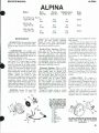
ALPINA
ALPINA
Model
Bore
mm (in.)
070, 070S, A70, Pro 70,
Super Pro 70S
51
(2.0)
P90, Pro 90,
Super Pro 90
54
(2.13)
P120, Pro 120,
Super Pro 120
58
(2.28)
MAINTENANCE
SPARK PLUG. Recommended spark
plug for all models is Champion CJ7Y.
Electrode gap should be 0.5 mm (0.020
in.).
Stroke
mm (in.)
Displacement
cc (cu. in.)
Drive
Type
Direct
34.5
70
(1.36)
(4.3)
39.1
(1.54)
(5.5)
45.5
(1.79)
(7.3)
90
Direct
120
equipped with a breaker-point ignition
system. All other models, including
Models 070 and 070S manufactured
after 1983, are equipped with a breakerless electronic ignition system.
Breaker-Point Ignition. BreakerCARBURETOR. All models are point gap should be 0.45-0.50 mm
equipped with a Tiiiotson HS diaphragm (0.018-0.020 in.). Air gap between ignicarburetor. Refer to Tiiiotson section of tion coil lamination and flywheel
CARBURETOR SERVICE section for magnets should be 0.45 mm (0.018 in.).
Use a suitable thread locking solution on
service and exploded views.
Initial adjustment of low speed mix- coil attaching screws. Ignition timing is
ture screw is lVs turns open on Super not adjustable, however, breaker-point
Pro 120, 2 turns open on Super Pro 90 gap will affect timing. Be sure breakerand PA turns open on all other models. point gap is adjusted correctly.
Initial adjustment of high speed mixture
screw is % turn open on Super Pro 120
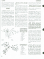
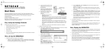
Electronic Ignition. Refer to Fig.
and ^k turn open on all other models. AP51 for exploded view of electronic igFinal adjustment should be made with nition system used on Models A70,
engine running at operating temp- Super Pro 70 and so equipped Models
erature. Adjust idle speed to just 070 and 070S. Note that coil (8) is
below clutch engagement speed. Adjust located outside of flywheel (1) while ignilow speed mixture screw so engine will tion module (13) is located behind
accelerate cleanly without hesitation. flywheel (1). Super Pro 90 and Super
Adjust high speed mixture screw to ob- Pro 120 models are equipped with
tain maximum speed of 10,300 rpm on electronic ignition system shown in Fig.
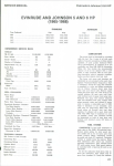
Super Pro 120, 9,700 rpm on Super Pro AP52. Ignition coil and all electronic cir90 and 10,500 rpm on all other models.
cuitry are contained in one-piece ignition
module (13).
Except for faulty wiring or wiring
IGNITION. Models 070 and 070S
manufactured prior to 1984 are connections, repair of ignition system
Direct
malfunctions is accomplished by component renewal.
On Super Pro 90 and Super Pro 120
models, air gap between ignition module
and flywheel magnets should be 0.65
mm (0.026 in.). Air gap between ignition
coil and flywheel magnets on all other
models should be 0.40 mm (0.016 in.).
Use a suitable thread locking solution on
module (or coil) attaching screws. Ignition timing is not adjustable on all
models.
Starter pawl assemblies (2, 3, 4 and
7-Fig. AP51) can be removed to accomodate a suitable bolt-type puller to
remove flywheel on all models. Use a
suitable thread locking solution on bolts
(2) when reassembling pawls. Tighten
flywheel nut to 39.2 N-m (29 ft.-lbs.) on
Super Pro 90 and Super Pro 120 models
and 28.4 N-m (21 ft.-lbs.) on all other
models.
LUBRICATION. The engine is
lubricated by mixing oil with the fuel.
Use a good quality oil designed for use in
air-cooled two-stroke engines. Fuehoil
mixture should be a 16:1 ratio. Use a
separate container when mixing fuel and
oil.
Models 070S and Super Pro 70 are
equipped with a manual and automatic
chain oil pump. All other models are only
equipped with an automatic chain oil
F/0. APSt^ Exploded vlaw
of electronic Ignition systam
usad on Models A70, Supar
Pro 70, and Modeis 070 and
070$ manufactured aftar
i983. Two pawi assambllas
(2f3, 4 and 7) are usad.
1. Flywheel
2. Bolt
3. Pawl
4. Spring
5. Nut
6. Washer
7. Washer
8. Ignition coil
9. Ignition switch
10. High tension lead
11. Cover
12. Module case
13. Module
Fig. APS2-Expiodad vlaw of aiactronic ignition
systam usad on Supar Pro 90 and Supar Pro 120
Rafar to Fig. AP51 for component
Idantlfication.
45
ALPINA
CHAIN SAW
NOTE: Do not install a new piston
pumf). Aut(»matic oil pump output is only
adjustable on Super F*ro 90 and Super marked "6" or "C" into a new cylinder
FVo 120 models. Refer to OIL FHJMF* marked "A."
under REPAIRS for service and exploded views of manual and automatic oil
Piston is equipped with two piston
pump assemblies. Use clean automotive rings. Piston should be inspected and
oil for saw chain lubrication.
renewed if cracking or scoring is noted.
Maximum allowable piston ring end gap
REPAIRS
is 1.0 mm (0.039 in.). Locating pins are
present in ring grooves to prevent ring
CYLINDER, PISTON, PIN AND rotation. Be certain ring end gaps are
RINGS. Cylinder bore is chrome plated properly positioned around locating pins
and should be renewed if cracking, scor- when installing cylinder. Tighten cylining or other damage is noted in cylinder der screws to 11.8 N-m (9 ft.-lbs.) on all
bore. Note that cylinder used on Super models.
Pro 90 and Super Pro 120 models is
On Models 070, 070S, A70 and Super
etjuipped with decompression valve Pro 70, piston pin (8-Fig. AP53) is a
(28-Fig. AP54) to ease starting.
press fit in connecting rod small end.
Piston and cylinder are matched dur- Piston rides in needle bearings (7) ining production to get desired piston-to- stalleci in each side of piston. Piston pin
cylinder clearance of 0.02 mm (0.0008 is retained with two snap rings (9). Use
in.). Original equipment piston and Alpina tool 4180020 or a suitable equivcylinder are marked "A." Factory alent press to remove and install f)iston
renew^al piston and cylinder assemblies pin. Be sure piston is properly supported
are marked "B." Piston or cylinder to prevent damage to piston.
marked T/' is 0.127 mm (0.005 in.) overOn all other models, piston pin
size. Piston or cylinder marked "D" is (8-F'ig. AP54) is a press fit in piston
0.127 mm (0.005 in.) undersize. Piston and rides in one needle bearing (7) inand cylinder markings should match, stalled in connecting rod small end.
however, a new piston marked "B" can Piston pin is retained with two wire clips
be installe(l into a used cylinder marked (9). Use Alpina tool 4180010 or a suit"A."
able equivalent to remove and install
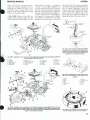
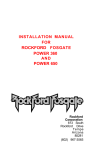
Fig. AP53-Expiodeci view
of engine assembiy, carburetor and reiated components used on ail models
except Super Pro 90 and
Super Pro 120. Two needle
bearings (7) are used. Refer
to text.
7.
8.
9.
10.
5. Piston rings
11,
12.
13.
14.
15.
16.
17.
18.
19.
6. Piston
20.
4. Gasket
22
46
Needle bearing
Piston pin
Snap rinf(
Crankshaft & connecting
rod assy.
Seal
Main bearing
Seal
Gasket
Gasket
Intake manifoici
Gasket
Carburetor
Plate
Screen
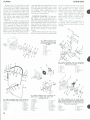
Fig. AP54-Expioded view
of engine assembiy used on
Super Pro 90 and Super Pro
120 modeis.
1. Cylinder
4. Gasket
5. Piston rings
6. Piston
7. Needle bearing
8. Piston pin
9. Wire clip
10. Crankshaft & connecting
rod assy.
21. Right crankcase half
22. Gasket
23. Seal
24. Main bearing
25. Main bearing
26. Seal
27. Left crankcase half
28. Decompression valve
f)iston pin. Piston may be heated to approximately 110°-120"' C (230^-248'' F)
to ease installation of f)iston pin.
NOTE: Use electric oven or hot oil bath
to heat piston. Do not jse an open flame.
On all models, ir stall piston into
cylinder with arrow on piston crown facing toward exhaust port.
CRANKSHAFT, CONNECTING
ROD AND CRANKCASE. Crankshaft
and connecting rod are available as a
unit assemltly only. <Jheck rotation of
connecting rod around crankpin and
renew crankshaft assembly if roughness, excessive play or other damage is
noted. Check crankshaft runout by supporting crankshaft between two counter
points such as a lathe. Make certain no
damage is present in centering holes at
each end of crankshaft. Renew
crankshaft assembly if runout exceeds
0.08 mm (0.0031 in.').
NOTE: Crankshaft runout can be
checked white still assembled in
crankcase. Remove clutch and flywheel
and mount dial indicators on each side of
crankshaft as close tc main bearings as
possible. Measure runout while rotating
crankshaft. Renew crankshaft assembly if
runout exceeds 0.07 mm (0.0027 in.) when
measured in this manrer.
Crankshaft is supported with l)al]-type
main bearings (12-F'ig. AP53) or (24
and 25-Fig. AP54) at both ends. Main
bearings are a ()ress fit into crankcase
halves. Use the f)r()per size drivers to
remove and install main bearings. Use
Alpina tool 4180900 or a suitable equivalent to install crankslaft assembly into
crankcase. Refer to F'ig. AP57. Do not
use gasket sealer on crankcase gasket.
Tighten crankcase screws using a
crisscross pattern to 7.8 N-m (69
in.-lbs.) on Super Pro 90 and Super Pro
120 models an(i 7.3 N-m (69 in.-lbs.) on
Super Pro 90 and Super Pro 120 models
and 7.3 N*m (65 in. lbs.) on all other
models.
CLUTCH. Late Models 070, 070S,
A70 and Super Pro 70 are equipped with
the clutch assembly shown in Fig. AP58.
Late Models Super Pro 90 and Super
Pro 120 are equipped with the clutch
assembly shown in Fig. AP60. Refer to
Fig. AP59 for view oi' shoes (4), hub (5)
and spring (3) used on all early models.
Note that hub ( 5 - Figs. AP58, AP59 and
AP60) is keyed to (crankshaft on all
models. Inspect shoes (4-Fig. AP58 or
Fig. AP60), drum (7) £,nd needle bearing
(9) for excessive wear or damage due to
overheating. Use Alpina tool 4180110 or
a suitable bolt-type puller to remove
ALPINA
SERVICE MANUAL
clutch. Nut (12) has right-hand threads.
Clutch shoes (4) are available only as a
complete set. Tighten nut (12) to 45.1
N-m (33 ft.-lbs.) on Super Pro 90 and
Super Pro 120 models and 35.3 N-m (26
ft.-lbs.) on all other models.
OIL PUMP. Refer to Fig. AP61 for
exploded view of manual chain oil pump
used on Models 070S and Super Pro 70.
Disassembly for repair or component
renewal is evident after inspection of
unit and referral to Fig. AP61. Hoses (4)
must be renewed if pump is disassembled. Be sure clamps (3) are tight and
properly installed to prevent leakage.
Refer to Fig. AP62 for exploded view
of automatic oil pump used on Models
070, 070S, A70 and Super Pro 70. Oil is
pumped by piston (5) which is rotated by
drive plate (10). Drive plate is cycled up
and down by plunger (15) which rides on
cam of engine crankshaft. Piston (5)
rotates one notch with each down stroke
of drive plate (10). Spring (12) forces
piston brake (13) against piston (5),
preventing piston (5) from backing up
during drive plate (10) return stroke.
Alpina Tool
4180900
22
Fig. AP57- View showing installation procedure
of crankshaft and connecting rod assembly into
crankcase haif using Alpina tooi 4180900. Main
bearing is pressed into crankcase haif prior to
installation of crankshaft assembly.
Fig. APSS-Expiodad viaw of crankcasa, front handle assembly, fual tank and related components
usad on Models 070, 070S and A70.
1. Cover
17. Screen
12. Choke lever
18. Fuel pickup
2. Air filter
7. Muffler cover
8. Right crankcase half
13. Throttle rod
19. Filter
3. Snap ring
9. Left crankcase half
4. Oit tank cap aijsy.
14. Grommet
20. "0" ring
10. Cylinder cover
5. Front handle
15. Clamp
21. Fuel tank
11. Trigger
6. Hand guard
16. Fuel hose
22. Vent valve
5
6
Fig. AP58—Exploded view of new design clutch
usad on late 070, 070S, A70 and Super Pro 70
models.
1.
2.
3.
4.
5.
6.
Bushing
Screw
Spring
Shoes
Hub
Woodruff key
7. Drum
Fig. APS6-Exploded view of crankcasa, front handia assambiy, rear grip assembly, fual tank and
related components used on Modal Super Pro 70. Refer to legend in Fig. AP55 for component identification except, safety ia¥ar(23}, vibration isolator (24) and rear grip assembly (25). Super Pro 90 and
Supar Pro 120 models are simiiar.
8.
9.
10.
U.
12.
Bushing
Needle bearing
Washer
Washer
Nut
13. Cover
Fig. APS9- View showing dutch shoes (4), hub
($) and spring (3) used on ail aariy models.
47
ALPINA
Plunger (15) is 31 mm (1.22 in.) long
when new. Renew plunger if worn shorter than 30.3 mm (1.193 in.). Renew drive
plate (10) if wear at piston contact area
exceeds 1.5 mm (0.059 in.) when compared with a new drive plate. Reservoir
(R) should be filled with high temperature lithium base grease and capped
with felt plug (20). Pump output is not
adjustable.
Refer to Fig. AP63 for exploded view
of adjustable automatic oil pump used on
Super Pro 90 and Super Pro 120 models.
Oil is pumped by piston (5) which is
rotated by worm gear (23) mounted on
engine crankshaft. Pump output is regulated by turning adjusting lever (28).
Renew piston and worm gear if excessive wear or damage is noted. Closely in-
CHAIN SAW
spect seal (30) and seal surface on worm
gear (23). Note that slight wear on seal
or worm gear may allow pump to draw
air causing pump malfunction. It is
recommended to renew seal (30) any
time pump is disassembled.
REWIND STARTER. To disassem
ble starter, remove rope handle (10Fig. AP64) and carefully allow rope to
wind into housing, relieving tension on
rewind spring (5). Remove screw (9) and
rope pulley (6) using caution not to
dislodge rewind spring (5). If rewind
spring (5) must be removed, use caution
not to allow spring to uncoil uncontrolled.
Install rewind spring (5) into housing
(2) in a clockwise direction starting with
outer coil. Install rope onto rope pulley
(6) in a clockwise direction as viewed
from flywheel side of pulley. Rotate
pulley (6) clockwise to apply tension on
rewind spring. Apply only enough tension on rewind spring (5) to pull rope
handle snug against housing. Rope
pulley should be able to rotate an additional V2 turn with n«pe completely extended.
Refer to V\^. AP51 for exploded view
of starter pawl assemblies. Use a
suitable thread lockin^j solution on pawl
bolts (2).
28
Fig. AP60-Exploded view
of clutch used on (ater Super
Pro 90 and Super Pro 120
models.
2.
3.
4.
rx
7.
y.
10.
11.
12.
14.
Screw
Spring
Shoes
Hub
Drum
Needle bearing
Washer
WashtT
Nut
Washer
30
Fig. AP63 —Exploded view of adjustable
automatic oii pump used on Super Pro 90 and
Super Pro 120 modeis.
24. Collar
25. Pin
26. Pin
27. Bushing
28. Adjusting lever
29. Spring
30. Seal
10
Fig. AP$1 - Exploded view of the manual oil
pump used on Modeis 070$ and Super Pro 70.
1. Clamp
10. Bolt
2. Pump body
11. Washer
;j. Clamp
12. Fitting
4. Hose
13. Oil pickup
5. Cotter pin
14. Tube
6. Piston
15. "E" ring
7. Spring
16. Washers
H. Spring
17. Seals
9. Tube
18. Washer
48
Fig. AP$2 — Expioded view of automatic oii
pump used on Modeis 070, 070S, A70
and Super Pro 70.
1. Banjo bolt
2. Washers
13. Piston brake
3. Pump body
14. Gasket,
4. "0" ring
15. Plunger
5. Piston
16. Seal
6. Cover
17. Fitting
7. Plug
18. Oil pickup
8. Tube
19. Module case
9. Hose
20. Felt plug
10. Drive plate
21. Cover
11. Pin
22. Flywheel
12. Spring
R. Reservoir
Fig. AP64-Exploded
view of rewind starter
used on Modefs 070, 070S, A70and Super Pro 70.
Super Pro 90 and Super Pro 120 modeis are
simiiar except, washer (1'^) is not used and shaft
(4) is part of housing {2}.
1. Bolt
2. Housing
7. Needle bearing
3. Washer
8. Washer
4. Shaft
9. Screw
5. Rewind spring
10. Rope handle
6. Ropf pulley
11. Washer
4