1
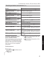
Installation and service
instructions
VIESMANN
for contractors
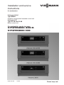
Vitotronic 300-K
Type MW1B
Weather-compensated cascade control unit
Vitotronic 100
Type GC1B and GC4B
Boiler control unit
For applicability, see the last page
VITOTRONIC 300-K
VITOTRONIC 100
5815 091 GB
7/2013
Please keep safe.
Safety instructions
Safety instructions
Please follow these safety instructions closely to prevent accidents and material losses.
Safety instructions explained
Danger
This symbol warns against the
risk of injury.
!
Please note
This symbol warns against the
risk of material losses and environmental pollution.
Note
Details identified by the word "Note" contain additional information.
Target group
These instructions are exclusively intended for qualified contractors.
■ Work on gas installations must only be
carried out by a registered gas fitter.
■ Work on electrical equipment must
only be carried out by a qualified electrician.
■ The system must be commissioned by
the system installer or a qualified person authorised by the installer.
Regulations
If you smell gas
Danger
Escaping gas can lead to explosions which may result in serious
injury.
■ Do not smoke. Prevent naked
flames and sparks. Do not
switch lights or electrical appliances on or off.
■ Close the gas shut-off valve.
■ Open windows and doors.
■ Evacuate any people from the
danger zone.
■ Notify your gas or electricity
supplier and your local heating
contractor from outside the
building.
■ Shut off the electricity supply to
the building from a safe place
(outside the building).
5815 091 GB
Observe the following when working on
this system:
■ Statutory regulations regarding the
prevention of accidents
■ Statutory regulations regarding environmental protection
■ The Code of Practice of relevant trade
associations
■ All current safety regulations as
defined by DIN, EN, DVGW, TRGI,
TRF, VDE and all locally applicable
standards
a ÖNORM, EN, ÖVGW-TR Gas,
ÖVGW-TRF and ÖVE
c SEV, SUVA, SVGW, SVTI,
SWKI, VKF and EKAS guideline
1942: LPG, part 2
2
Safety instructions
Safety instructions (cont.)
If you smell flue gas
Danger
The simultaneous operation of
the boiler and appliances that
extract air to the outside can
result in life threatening poisoning due to reverse flow of the flue
gas.
Fit an interlock circuit or take suitable steps to ensure a sufficient
supply of combustion air.
Danger
Flue gas can lead to life threatening poisoning.
■ Shut down the heating system.
■ Ventilate the installation site.
■ Close all doors in the living
space.
Flue systems and combustion air
Working on the system
Ensure that flue systems are clear and
cannot be sealed, for instance due to
accumulation of condensate or other
causes. Ensure a sufficient supply of
combustion air.
Instruct system users that subsequent
modifications to the building characteristics are not permissible (e.g. cable/pipework routing, cladding or partitions).
Danger
Leaking or blocked flue systems,
or an insufficient supply of combustion air can cause life threatening poisoning from carbon
monoxide in the flue gas.
Ensure the flue system is in
proper working order. Apertures
for supplying combustion air
must be non-closable.
5815 091 GB
Extractors
Operating appliances that extract air to
the outside (cooker hoods, extractors, air
conditioning units, etc.) can create negative pressure. If the boiler is operated at
the same time, this can lead to reverse
flow of the flue gas.
■ Where gas is used as the fuel, close
the main gas shut-off valve and safeguard it against unintentional reopening.
■ Isolate the system from the power supply (e.g. by removing the separate fuse
or by means of a mains isolator) and
check that it is no longer 'live'.
■ Safeguard the system against reconnection.
Danger
Hot surfaces can cause burns.
■ Before maintenance or service
work, switch OFF the appliance and let it cool down.
■ Never touch hot surfaces on
the boiler, burner, flue system
or pipework.
!
Please note
Electronic assemblies can be
damaged by electrostatic discharge.
Before beginning work, touch
earthed objects, such as heating
or water pipes, to discharge static
loads.
3
Safety instructions
Safety instructions (cont.)
Repair work
!
Please note
Repairing components that fulfil a
safety function can compromise
the safe operation of the system.
Faulty components must be
replaced with original Viessmann
spare parts.
Auxiliary components, spare and
wearing parts
Please note
Spare and wearing parts that
have not been tested together
with the system can compromise
its function. Installing non-authorised components and making
non-approved modifications or
conversions can compromise
safety and may invalidate the
warranty.
For replacements, use only original spare parts supplied or
approved by Viessmann.
5815 091 GB
!
4
Index
Index
Installation instructions
Intended use.......................................................................................................
9
Installation, Vitotronic 100
Overview of electrical connections.......................................................................
Inserting cables and applying strain relief............................................................
Inserting the boiler coding card............................................................................
Changing over the high limit safety cut-out..........................................................
Changing the temperature controller setting........................................................
Inserting the LON communication module...........................................................
Connecting sensors..............................................................................................
Connecting pumps...............................................................................................
Connecting actuators...........................................................................................
Connecting a central fault message facility..........................................................
Connecting the external safety equipment...........................................................
Provisional burner operation................................................................................
External burner blocking.......................................................................................
External changeover of multi stage/modulating burners......................................
Blocking the boiler externally/starting in the boiler sequence..............................
Connecting the AC burner, type GC1B................................................................
Connecting the three-phase burner, type GC1B..................................................
10
13
14
15
16
18
18
19
21
21
22
23
23
24
25
26
30
Installation, Vitotronic 300-K
Overview of electrical connections.......................................................................
Inserting cables and applying strain relief............................................................
Connecting sensors..............................................................................................
Connecting pumps...............................................................................................
Connecting actuators...........................................................................................
Connecting a central fault message facility..........................................................
External demand via switching contact................................................................
External demand via 0 – 10 V input.....................................................................
External blocking via switching contact................................................................
External "Mixer close"/"Mixer open".....................................................................
External heating program changeover.................................................................
Making the LON connection.................................................................................
33
35
35
36
37
38
38
39
40
41
42
44
5815 091 GB
Power supply of the Vitotronic 100 and Vitotronic 300-K
Power supply........................................................................................................ 47
Opening and closing the Vitotronic 100 and Vitotronic 300-K control units
Fitting the control unit front................................................................................... 51
Opening the control unit....................................................................................... 52
5
Index
Index
Service instructions
Commissioning, Vitotronic 100 and Vitotronic 300-K
Commissioning steps...........................................................................................
Testing the high limit safety cut-out......................................................................
Selecting the language.........................................................................................
Setting the date and time.....................................................................................
Matching up the coding addresses.......................................................................
Selecting the boiler sequence..............................................................................
Connecting the control unit to the LON................................................................
Checking actuators and sensors..........................................................................
Adjusting the heating curve..................................................................................
53
53
54
54
54
57
58
61
64
Service scans, Vitotronic 100
Calling up the service menu.................................................................................
Exiting the service menu......................................................................................
Scanning operating data......................................................................................
Brief scan.............................................................................................................
Service indicator...................................................................................................
67
67
67
67
69
Service scans, Vitotronic 300-K
Calling up the service menu.................................................................................
Exiting the service menu......................................................................................
Scanning operating data......................................................................................
Resetting operating data......................................................................................
Brief scan.............................................................................................................
Service indicator...................................................................................................
70
70
70
71
71
73
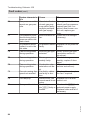
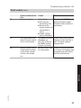
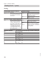
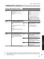
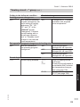
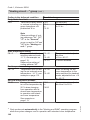
Troubleshooting Vitotronic 100
Fault display......................................................................................................... 74
Fault codes........................................................................................................... 75
Function description, Vitotronic 100 and Vitotronic 300-K
Boiler control unit Vitotronic 100, type GC1B....................................................... 97
Boiler control unit Vitotronic 100, type GC4B....................................................... 100
Cascade control of the Vitotronic 300-K............................................................... 100
Heating circuit control of the Vitotronic 300-K...................................................... 106
Cylinder temperature control of the Vitotronic 300-K........................................... 115
6
5815 091 GB
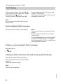
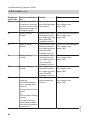
Troubleshooting Vitotronic 300-K
Fault display......................................................................................................... 86
Fault codes........................................................................................................... 87
Index
Index
Code 1, Vitotronic 100
Calling up coding level 1...................................................................................... 119
Group 1................................................................................................................ 119
Group 2................................................................................................................ 120
Code 2, Vitotronic 100
Calling up coding level 2...................................................................................... 122
Group 1................................................................................................................ 122
Group 2................................................................................................................ 125
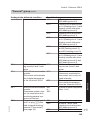
Code 1, Vitotronic 300-K
Calling up coding level 1...................................................................................... 130
"General" group.................................................................................................... 130
"Cascade" group.................................................................................................. 132
"DHW" group........................................................................................................ 134
"Solar" group........................................................................................................ 134
"Heating circuit ..." group...................................................................................... 136
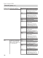
Code 2, Vitotronic 300-K
Calling up coding level 2...................................................................................... 142
"General" group.................................................................................................... 142
"Cascade" group.................................................................................................. 151
"DHW" group........................................................................................................ 154
"Solar" group........................................................................................................ 158
"Heating circuit ..." group...................................................................................... 162
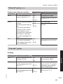
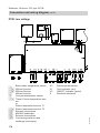
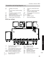
Schemes, Vitotronic 100, type GC1B
Connection and wiring diagram............................................................................ 170
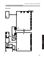
Schemes, Vitotronic 100, type GC4B
Connection and wiring diagram............................................................................ 175
5815 091 GB
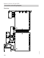
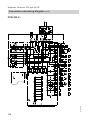
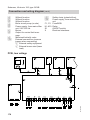
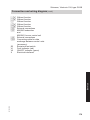
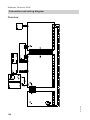
Schemes, Vitotronic 300-K
Connection and wiring diagram............................................................................ 180
Components, Vitotronic 100, type GC1B and Vitotronic 300-K
Boiler coding card................................................................................................. 185
Sensors................................................................................................................ 185
Plug-in adaptor for external safety equipment...................................................... 187
Radio clock receiver............................................................................................. 189
Mixer extension kit................................................................................................ 190
Mixer motor.......................................................................................................... 191
Mixer motor.......................................................................................................... 193
7
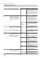
Index
Index (cont.)
Temperature limiter for limiting the maximum temperature.................................. 195
EA1 extension...................................................................................................... 196
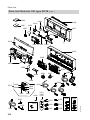
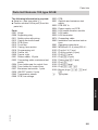
Parts lists
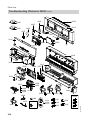
Parts list Vitotronic 100, type GC1B..................................................................... 199
Parts list Vitotronic 100, type GC4B..................................................................... 201
Troubleshooting Vitotronic 300-K......................................................................... 203
Specification
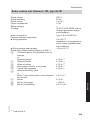
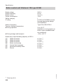
Boiler control unit Vitotronic 100, type GC1B....................................................... 205
Boiler control unit Vitotronic 100, type GC4B....................................................... 206
Specification Vitotronic 300-K.............................................................................. 207
5815 091 GB
Keyword index.................................................................................................... 208
8
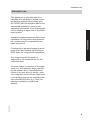
Intended use
Intended use
The appliance is only intended to be
installed and operated in sealed unvented heating systems that comply with
EN 12828, with due attention paid to the
associated installation, service and
operating instructions. It is only designed
for the heating of water that is of potable
water quality.
Installation
Intended usage presupposes that a fixed
installation in conjunction with permissible, system-specific components has
been carried out.
Commercial or industrial usage for a purpose other than heating the building or
DHW does not comply with regulations.
Any usage beyond this must be
approved by the manufacturer for the
individual case.
5815 091 GB
Incorrect usage or operation of the appliance (e.g. the appliance being opened
by the system user) is prohibited and
results in an exclusion of liability. Incorrect usage also occurs if the components
in the heating system are modified from
their intended function (e.g. if the flue
gas and ventilation air paths are
sealed).
9
Installation, Vitotronic 100
Overview of electrical connections
■ Observe the requirements of safety
category II when connecting external
switching contacts or components to
the safety LV of the control unit. That is
8.0 mm air and creep paths and
2.0 mm insulation thickness against
'live' components.
■ Ensure the safe electrical separation
of all on-site components (incl. PC/laptops) conforms to EN 60 335 or
IEC 65.
5815 091 GB
Danger
Incorrect wiring can lead to serious injury from electrical current
and result in appliance damage.
■ Route LV leads < 42 V and
> 42 V/230 V~/400 V~ cables
separately.
■ Strip the insulation from the
cables as close to the terminals
as possible, and bundle tightly
to the corresponding terminals.
■ Secure cables with cable ties.
This ensures that, should there
be a fault, for example when
detaching a wire, the wires cannot drift into the adjacent voltage
area.
10
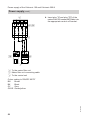
Installation, Vitotronic 100
Overview of electrical connections (cont.)
Installation
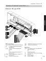
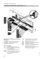
Vitotronic 100, type GC1B
145
145
3/2
151
90
17 A
17 B
15
41
5815 091 GB
143
146
52 A1
20 A1
29
50
40
156
156
PCB, low voltage
§/? Boiler water temperature sensor
Flue gas temperature sensor
aG
(accessory)
aJA Therm-Control temperature
sensor
or
Return temperature sensor T1
(accessory)
aJB Return temperature sensor T2
(accessory)
External connections
aVD
150
aVG
aVH
KM BUS subscriber (accessory)
External connections
PCB 230 V~
sÖA1 Circulation pump, flue gas/water
heat exchanger
or
Switching output
Shunt pump or boiler circuit pump
sL
(on site)
Power supply
fÖ
Burner stage 1
fA
11
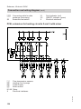
Installation, Vitotronic 100
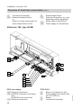
Overview of electrical connections (cont.)
Central fault message
gÖ
gSA1 Motorised butterfly valve
or
Motor for 3-way mixing valve for
return temperature control
lÖ
aBÖ
aBA
aBH
Burner stage 2/mod.
External connections, e.g. supplementary safety equipment
Safety chain, potential-free
Power supply for accessories
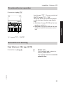
Vitotronic 100, type GC4B
145
145
151
41
143
146
52 A1
150
PCB, low voltage
aVD External connections
aVG KM BUS subscriber (accessory)
and
KM BUS burner control unit
aVH External connections
12
PCB 230 V~
Boiler circuit pump (on site)
sL
Power supply, from mains filter
fÖ
unit, 230 V/50 Hz
Burner
fA
Central fault message
gÖ
5815 091 GB
29
50
40
156
156
Installation, Vitotronic 100
Overview of electrical connections (cont.)
gSA1 Motorised butterfly valve
aBÖ External connections, e.g. supplementary safety equipment
aBA
aBH
Safety chain, potential-free
Power supply, from mains filter
unit
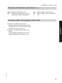
Inserting cables and applying strain relief
5815 091 GB
Installation
■ Control unit fitted to the boiler:
Route cables from below through the
front panel of the boiler into the wiring
chamber of the control unit.
■ Control unit fitted on the side of the
boiler:
Route cables from below out of the
cable trunking into the control unit.
13
Installation, Vitotronic 100
Inserting cables and applying strain relief (cont.)
A
D
C
D
B
A Cables with moulded strain relief
B On-site cables; strip up to 100 mm
of insulation.
C Plug-in connection diagram
D Female mouldings for plug-in connection diagram
Inserting the boiler coding card
5815 091 GB
Only use the boiler coding card supplied
with the boiler (see page 185).
14
Installation, Vitotronic 100
Inserting the boiler coding card (cont.)
Installation
X7
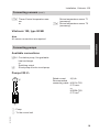
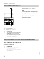
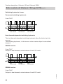
Changing over the high limit safety cut-out
Only Vitotronic 100, type GC1B
The high limit safety cut-out is supplied
with a factory setting of 110 °C.
110 °C
100 °C
95 °C
100 °C
87 °C
85 °C
120 °C
110 °C
105 °C
90 °C
80 °C
100 °C
5815 091 GB
High limit safety cut-out
Temperature controller
Electronic maximum boiler water temperature limit,
coding address "06" in group 2 "Boiler" on the
Vitotronic 100
Electronic maximum flow temperature limit, coding
address "37" in the "Cascade" group on the
Vitotronic 300-K
15
Installation, Vitotronic 100
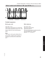
Changing over the high limit safety cut-out (cont.)
2.
1.
95
110 1
2
0
3.
°C
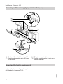
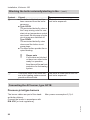
Changing the temperature controller setting
Only Vitotronic 100, type GC1B
The temperature controller is supplied
with a factory setting of 95 °C.
Please note
Excessive DHW temperatures
can damage the DHW cylinder.
If the system operates with a
DHW cylinder, ensure that the
maximum permissible DHW temperature is not exceeded. If necessary, install suitable safety
equipment for this purpose.
5815 091 GB
!
16
Installation, Vitotronic 100
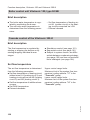
Changing the temperature controller setting (cont.)
A
Installation
2.
1.
3.
A 75 to 100 °C
1. Remove rotary selector " ".
5815 091 GB
2. Using a pair of pointed pliers, break
tab A identified in the illustration out
of the stop dial.
3. Fit rotary selector " " so that the
marking lies at the centre of the selected range. Turn rotary selector " "
fully clockwise.
17
Installation, Vitotronic 100
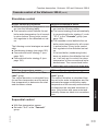
Inserting the LON communication module
Making the LON connection, see
page 44.
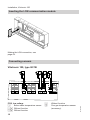
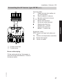
Connecting sensors
Vitotronic 100, type GC1B
2 1
2 1 2 1
2 1 2 1
3/2
5A 5B
17A 17B
PCB, low voltage
Boiler water temperature sensor
§
%A Without function
%B Without function
18
2 1 2 1
)
aG
15
9
Without function
Flue gas temperature sensor
(accessory)
5815 091 GB
2 1 2 1
145 145
Installation, Vitotronic 100
Connecting sensors (cont.)
aJA Therm-Control temperature sensor
or
Return temperature sensor T1
(accessory)
aJB Return temperature sensor T2
(accessory)
Vitotronic 100, type GC4B
Installation
Note
No sensor connections are required.
Connecting pumps
Available connections
sÖA1 Circulation pump, flue gas/water
heat exchanger
or
Switching output
Shunt pump or boiler circuit pump
sL
Pumps 230 V~
M A
1~
Rated current
4(2) A~
Recommended
connecting cable H05VV-F3G
0.75 mm2
or
H05RN-F3G
0.75 mm2
B
5815 091 GB
A Pump
B To the control unit
19
Installation, Vitotronic 100
Connecting pumps (cont.)
Pumps with power consumption greater than 2 A
N
L
D
L N
L
C
N
External
ON/OFF
B
A Pump
B To the control unit
C Contactor
L N PE
A
D Separate power connection
(observe manufacturer's details)
Pumps 400 V~
N
L
L1 L2 L3 N PE
For switching the contactor
Rated current
4(2) A~
Recommended
connecting cable H05VV-F3G
0.75 mm2
or
H05RN-F3G
0.75 mm2
C
B
M
A 3~
5815 091 GB
A Pump
B To the control unit
C Contactor
20
Installation, Vitotronic 100
Connecting actuators
Available connections
M
1~
52
Vitotronic 100, type GC4B
Motorised butterfly valve
Rated voltage
Rated current
Recommended connecting cable
Runtime
230 V~
Max. 0.2 (0.1) A~
H05VV-F4G0.75 mm2
or
H05RN-F4G 0.75 mm2
5 to 199 s,
adjustable at coding address "40" in group 1
"General".
Open
Close
Connecting a central fault message facility
L
N
5815 091 GB
50
Rated voltage
230 V~
Rated current
Max. 4 (2) A~
Recommended
connecting cable H05VV-F3G
0.75 mm2
or
H05RN-F3G
0.75 mm2
Note
Only fault messages from this one
Vitotronic 100 will be passed on. If faults
from the entire system are to be passed
on, use plug gÖ of the Vitotronic 300-K.
21
Installation
Vitotronic 100, type GC1B
Motorised butterfly valve
or
Motor for 3-way mixing valve,
return temperature control
gSA1
Installation, Vitotronic 100
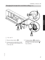
Connecting the external safety equipment
Connection via plug aBÖ.
The plug-in adaptor for external safety
equipment (accessory, see chapter
"Components") can be used for connecting several pieces of safety equipment.
!
Please note
'Live' contacts lead to short circuits or phase failure.
The external connections must
be potential-free.
Note
Plug aBÖ must remain plugged in, even
if no connection is made.
STB
B
P
C
P
D
P
ON ON
N STB TR TR
A
150
C Maximum pressure limiter
D Further safety equipment
1. Remove jumper "STB" – "STB".
2. Connect the external safety equipment in series to plug aBÖ.
5815 091 GB
A Jumper "STB" – "STB"
B Low water indicator, minimum pressure limiter
22
Installation, Vitotronic 100
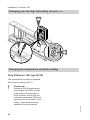
Provisional burner operation
STB
EIN EIN
N STB TR TR
Insert jumper "TR" – " burner control unit
ON/TR" across "TR" – "ON".
The boiler heats up with burner stage 1
or with the lower heating output/base
load.
■ Shutdown for type GC1B via the temperature controller
■ Shutdown for type GC4B via the temperature limiter in the burner control
unit
A
A Jumper "TR" – "ON/TR"
External burner blocking
Only Vitotronic 100, type GC1B
!
Please note
'Live' contacts lead to short circuits or phase failure.
The external connection must be
potential-free.
5815 091 GB
Connection on plug aBÖ.
23
Installation
Connection at plug aBÖ.
Installation, Vitotronic 100
External burner blocking (cont.)
Remove jumper "TR" – "ON/TR".
A
STB
EIN EIN
Note
Connect only safety shutdown equipment, e.g. temperature limiter, to these
terminals.
Opening this contact leads to a controlled burner shutdown.
N STB TR TR
B
A Floating contact
B Jumper "TR" – "ON/TR"
!
Please note
The heating system has no frost
protection while it is blocked.
The boiler is not held at the lower
boiler water temperature.
External changeover of multi stage/modulating burners
Only Vitotronic 100, type GC1B
Connection at plug aVH.
Please note
'Live' contacts lead to short circuits or phase failure.
The external connection must be
potential-free.
5815 091 GB
!
24
Installation, Vitotronic 100
External changeover of multi stage/modulating… (cont.)
Code
A
Set code "02:2" in group 2.
1 2 3
Note
When scanning the burner version, the
address for modulation appears even
after an external changeover (no rewriting).
146
Installation
A External changeover
(floating contact)
Contact open: Modulating operation
Contact closed: Two-stage operation
Blocking the boiler externally/starting in the boiler sequence
Connection at plug aVD.
!
A
Please note
'Live' contacts lead to short circuits or phase failure.
The external connection must be
potential-free.
B
1 2 3
143
5815 091 GB
A Blocking the boiler externally
(floating contact for switching LV)
B Starting the boiler externally as the
last one in the boiler sequence
(floating contact for switching LV)
25
Installation, Vitotronic 100
Blocking the boiler externally/starting in the… (cont.)
Contact
A
Closed
Open
■ The boiler is blocked and has
The boiler is made part of the curbeen removed from the boiler
rent boiler sequence.
sequence.
■ Type GC1B:
The motorised butterfly valve or
the 3-way mixing valve for constant return temperature control
are closed. Shunt pump or boiler
circuit pump are switched off.
Type GC4B:
The motorised butterfly valve
closes and the boiler circuit
pump stops.
■ The other boilers provide the required heating.
!
B
Please note
If all boilers are blocked
or there is no other boiler
ready for operation,
then there will be no frost
protection for the heating
system.
This boiler starts if the other boilers in the heating system cannot
provide sufficient heat.
The boiler is made part of the current boiler sequence.
Connecting the AC burner, type GC1B
Pressure-jet oil/gas burners
Max. power consumption 6 (3) A.
5815 091 GB
The burner cables are part of the standard boiler delivery.
Connect the burner in accordance with
DIN 4791 [or local regulations].
26
Installation, Vitotronic 100
Terminal codes
L1
Phase via high limit safety cutout to the burner
PE
Earth conductor to burner
N
Neutral conductor to burner
T1, T2 Control chain
S3
Burner fault terminal
B4
Hours run meter terminal
Signal pass direction:
Control unit → burner
Signal pass direction:
Burner → control unit
41
L1
TR
N
BZ
Störung H1
N
PE
L1
N T1 T2 S3 B4
STB
L
41
T1 T2 S3 B4
Equipment codes
STB Control unit high limit safety cutout
TR Control unit temperature controller
H1 Burner fault signal
BZ Hours run meter
A To the control unit
B To the burner
Burner without plug
5815 091 GB
Fit the mating plug from Viessmann or
from the burner manufacturer. Connect
the burner cable.
27
Installation
Connecting the AC burner, type GC1B (cont.)
Installation, Vitotronic 100
Connecting the AC burner, type GC1B (cont.)
90
T6 T7T8
BN
BK
BU
Terminal codes
T6, T8 Control chain burner stage 2 ON
or modulation controller Open
T6, T7 Control chain burner stage 2
OFF or modulation controller
Close
Signal pass direction:
Control unit → burner
Signal pass direction:
Burner → control unit
Colour coding to DIN/IEC 60757
BK Black
BN Brown
BU Blue
A To the control unit
B To the burner
Viessmann MatriX burner for Vitocrossal
Max. power consumption 6 (3) A.
5815 091 GB
The burner cables are part of the standard boiler delivery.
28
Installation, Vitotronic 100
A
L
N T1 T2 S3 B4
41
B4 S3 T2 T1 N
Terminal codes
L1
Phase via high limit safety cutout to the burner
PE
Earth conductor to burner
N
Neutral conductor to burner
T1, T2 Control chain
S3
Burner fault terminal
B4
Hours run meter terminal
Signal pass direction:
Control unit → burner
Signal pass direction:
Burner → control unit
L
41
B
5815 091 GB
A To the control unit
B To the burner
29
Installation
Connecting the AC burner, type GC1B (cont.)
Installation, Vitotronic 100
Connecting the AC burner, type GC1B (cont.)
A
90
T6 T7T8
BN
BK
BU
Terminal codes
T6, T8 Control chain burner stage 2 ON
or modulation controller Open
T6, T7 Control chain burner stage 2
OFF or modulation controller
Close
Colour coding to DIN/IEC 60757
BK Black
BN Brown
BU Blue
BN
BK
BU
90
T6 T7T8
B
A To the control unit
B To the burner
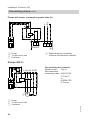
Connecting the three-phase burner, type GC1B
Safety chain, potential-free
5815 091 GB
Note
If there is a jumper from the external conductor to the control voltage in the
burner, it may have to be removed.
Always observe the burner manufacturer's details.
30
Installation, Vitotronic 100
Connecting the three-phase burner, type GC1B (cont.)
F2
TR
K1
A
Installation
T6 T7 T8
a
B
C
A
B
C
D
E
F
G
H
K
D
E
GH K
F
Control unit
Main contactor (on site)
Three-phase burner
Burner power supply
Main contactor switching
Safety chain (high limit safety cutout), potential-free
Control chain stage 1/base load
Burner fault message
Hours run meter stage 1
L
L
fÖ
fA
lÖ
aBÖ
Base load/full load
Control unit power supply
Burner, stage 1
Burner, stage 2
Plug for external connections
a External safety equipment;
remove jumper when connecting
aBA Safety chain, potential-free,
remove jumper when connecting
5815 091 GB
Safety chain not potential-free
Note
If there is a jumper from the external conductor to the control voltage in the burner,
it may have to be removed.
Always observe the burner manufacturer's details.
31
Installation, Vitotronic 100
Connecting the three-phase burner, type GC1B (cont.)
F2
TR
K1
A
T6 T7 T8
a
B
C
D
FG H
K
E
Control unit
Main contactor (on site)
Three-phase burner
Burner power supply
Main contactor switching
Control chain stage 1/base load
Burner fault message
Hours run meter stage 1
Base load/full load
fÖ
fA
lÖ
aBÖ
Control unit power supply
Burner, stage 1
Burner, stage 2
Plug for external connections
a External safety equipment;
remove jumper when connecting
aBA Safety chain (STB)
5815 091 GB
A
B
C
D
E
F
G
H
K
32
Installation, Vitotronic 300-K
■ Observe the requirements of safety
category II when connecting external
switching contacts or components to
the safety LV of the control unit. That is
8.0 mm air and creep paths and
2.0 mm insulation thickness against
'live' components.
■ Ensure the safe electrical separation
of all on-site components (incl. PC/laptops) conforms to EN 60 335 or
IEC 65.
5815 091 GB
Danger
Incorrect wiring can lead to serious injury from electrical current
and result in appliance damage.
■ Route LV leads < 42 V and
> 42 V/230 V~/400 V~ cables
separately.
■ Strip the insulation from the
cables as close to the terminals
as possible, and bundle tightly
to the corresponding terminals.
■ Secure cables with cable ties.
This ensures that, should there
be a fault, for example when
detaching a wire, the wires cannot drift into the adjacent voltage
area.
33
Installation
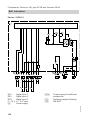
Overview of electrical connections
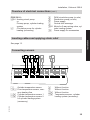
Installation, Vitotronic 300-K
Overview of electrical connections (cont.)
LON
M3
M2
M3
M2
M3
M2
145
145
1
3/2
5 A
5 B
17 B
143
146
28
21
52 A1
20 A1
29
50
40
156
Extension for heating circuits 2 and 3
with mixer
? M2/M3 Flow temperature sensor
sÖ M2/M3 Heating circuit pump
gS M2/M3 Mixer motor
PCB, low voltage
Outside temperature sensor
!
§/? Flow temperature sensor, common heating flow
%A Cylinder temperature sensor
%B Cylinder temperature sensor 2
for cylinder loading system
(accessory)
34
aJB Temperature sensor, cylinder
loading system (accessory)
External connections
aVD
KM BUS subscriber (accessory)
aVG
External connections
aVH
LON BUS, connecting cable for
¡¢£
data exchange with the
Vitotronic 100, Vitotronic 200-H,
Vitocom and Vitogate
5815 091 GB
52
52
20
20
2
2
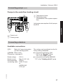
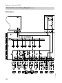
Installation, Vitotronic 300-K
Overview of electrical connections (cont.)
sK
sL
fÖ
gÖ
gSA1
PCB 230 V~
sÖA1 Heating circuit pump
or
Primary pump, cylinder loading
system
Circulation pump for cylinder
sA
heating (accessory)
aBH
DHW circulation pump (on site)
Distribution pump (on site)
Power supply
Central fault message
Motor for 3-way mixing valve, cylinder loading system
Power supply for accessories
Installation
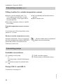
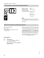
Inserting cables and applying strain relief
See page 13.
Connecting sensors
1
2 1 2 1
3 2 1
2 1
2 1 2 1
2 1
2 1
2 1
2 1
145 145
1
3/2
5A 5B
17A
17B
15
9
)
aG
aJA
aJB
Without function
Without function
Without function
Temperature sensor, cylinder
loading system (accessory)
5815 091 GB
Outside temperature sensor
!
§/? Flow temperature sensor, common heating flow
%A Cylinder temperature sensor 1
%B Cylinder temperature sensor 2
for cylinder loading system
(accessory)
35
Installation, Vitotronic 300-K
Connecting sensors (cont.)
Fitting location for outside temperature sensor
■ North or north-westerly wall, 2 to
2.5 m above ground level; in multi
storey buildings, in the upper half of
the second floor.
■ Not above windows, doors or ventilation outlets.
■ Not immediately below balconies or
gutters.
■ Never render over.
Outside temperature sensor connection
2-core lead, up to 35 m long with a crosssection of 1.5 mm2
Wireless outside temperature sensor
Wireless subscriber. Only in connection
with the wireless base station (KM BUS
subscriber) that is connected to the
Vitotronic control unit.
Wireless base station installation
and service instructions
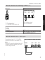
Connecting pumps
Available connections
sÖ Heating circuit pump
or
Primary pump, cylinder loading system
sA Circulation pump for cylinder heating
sK DHW circulation pump
sL Shunt pump or distribution pump
Pumps 230 V~ and 400 V~
5815 091 GB
Connection, see page 19.
36
Installation, Vitotronic 300-K
Connecting pumps (cont.)
Pumps in the underfloor heating circuit
B Temperature limiter
C Secondary pump
(downstream of the system separation)
sÖ
N
20
L
Joint power consumption of both pumps:
max.2 A
A
M
1~
B
Installation
M
1~
C
sÖ Control unit
A Primary pump
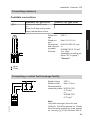
Connecting actuators
Available connections
gSA1
Motor for 3-way mixing valve,
cylinder loading system
gSM2/M3 Mixer motor
Connection, see page 21.
230 V~
Max. 0.2 (0.1) A~
H05VVF4G0.75 mm2
or
H05RN-F4G
0.75 mm2
5815 091 GB
Rated voltage
Rated current
Recommended
connecting cable
The runtime can be adjusted via the following coding addresses:
■ in conjunction with plug gSA1:
– "40" in the "General" group
"6A" in the "DHW" group
■ in conjunction with plug gSM2/M3:
"C3" in the "Heating circuit" group
37
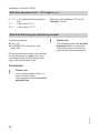
Installation, Vitotronic 300-K
Connecting a central fault message facility
L
Rated voltage
230 V~
Rated current
Max. 4 (2) A~
Recommended
connecting cable H05VV-F3G
0.75 mm2
or
H05RN-F3G
0.75 mm2
N
50
Note
All heating system faults are passed on.
This includes boiler control unit faults, for
example.
External demand via switching contact
Connection options:
■ Plug aVH
■ EA1 extension (accessory, see
page 196)
With the contact closed, the boiler burners are started subject to load. They heat
to the set flow temperature selected in
coding address "9b" in the "General"
group. The temperature is limited by this
set value and the electronic maximum
flow temperature limit (coding address
"37" in the "Cascade" group).
Connection
Please note
'Live' contacts lead to short circuits or phase failure.
The external connection must be
potential-free.
5815 091 GB
!
38
Installation, Vitotronic 300-K
External demand via switching contact (cont.)
Plug aVH
A
EA1 extension
DE
[{A
DE
[{S
B
DE
[{D
1 2 3
146
A Floating contact
B Plug aVH of the control unit
A
Installation
B
A Floating contact
B EA1 extension
Codes
Plug aVH
No coding required.
EA1 extension
Set "5d" (DE1), "5E" (DE2) or "5F" (DE3)
in the "General" group to 2.
External demand via 0 – 10 V input
Connection at input 0 – 10 V to EA1
extension (accessory, see page 196).
Note
Ensure DC separation between the earth
conductor and the negative pole of the
on-site voltage source.
0-10V
[{{]
aBJ
+-
SÖ P
A
f-]
L
fÖ
N N
L
5815 091 GB
U
+
39
Installation, Vitotronic 300-K
External demand via 0 – 10 V input (cont.)
0 – 1 V ≙ No default set flow temperature
1V
≙ Set value 10 °C
10 V
≙ Set value 100 °C
Observe coding address "1E" in the
"General" group.
External blocking via switching contact
Connection options:
■ Plug aVD
■ Extension EA1 (accessory, see
page 196)
!
Please note
The heating system has no frost
protection while it is blocked.
The boilers are not held at the
lower boiler water temperature.
Closing this contact leads to a controlled
burner shutdown on each boiler. Any
connected shunt or distribution pump
stops. Shut-off devices close.
Connection
Please note
'Live' contacts lead to short circuits or phase failure.
The external connection must be
potential-free.
5815 091 GB
!
40
Installation, Vitotronic 300-K
External blocking via switching contact (cont.)
Plug aVD
A
EA1 extension
DE
[{A
DE
[{S
B
DE
[{D
1 2 3
143
A Floating contact
B Plug aVD of the control unit
Installation
A
B
A Floating contact
B EA1 extension
Codes
Plug aVD
In coding address "99" in the "General"
group determine, what the input should
influence.
EA1 extension
Set "5d" (DE1), "5E" (DE2) or "5F" (DE3)
in the "General" group to 3 or 4.
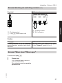
External "Mixer close"/"Mixer open"
Connection at plug aVD.
Please note
'Live' contacts lead to short circuits or phase failure.
The external connection must be
potential-free.
5815 091 GB
!
41
Installation, Vitotronic 300-K
External "Mixer close"/"Mixer open" (cont.)
A
B
1 2 3
143
A External "Mixer open"
(floating contact)
B External "Mixer close"
(floating contact)
Codes
External "Mixer open"
In coding address "9A" in the "General"
group, assign the function to the heating
circuits.
External "Mixer close"
In coding address "99" in the "General"
group, assign the function to the heating
circuits.
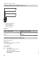
External heating program changeover
Optional connections:
■ Plug aVD
■ Extension EA1 (accessory, see chapter "Components")
!
42
Please note
'Live' contacts lead to short circuits or phase failure.
The external connection must be
potential-free.
5815 091 GB
Connection
Installation, Vitotronic 300-K
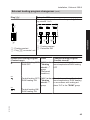
External heating program changeover (cont.)
Plug aVD
A
Extension EA1
The changeover can be achieved separately for heating circuits 1 to 3.
B
DE1
DE3
DE2
1 2 3
143
A
A
A
Installation
B
A Floating contact
A Floating contact
B Extension EA1
B Plug aVD on control unit
Changed heating program
(Contact closed)
Constant operation with reduced
room temperature/DHW heating
OFF
Constant operation with standard
room temperature, DHW heating
in accordance with coding address "64" in the "DHW" group
5815 091 GB
Preselected heating program
Code
(Contact open)
Central heating OFF/ "d5:0" in the
DHW OFF
"Heating
circuit ..."
group
(Delivered
condition)
or
Central heating OFF/ "d5:1" in the
DHW heating ON
"Heating
circuit ..."
group
or
Central heating ON/
DHW heating ON
43
Installation, Vitotronic 300-K
External heating program changeover (cont.)
Codes
Plug aVD
Via coding address "91" in the
"General" group, the function
can be assigned to the heating
circuits.
Extension EA1
Set "5d" (DE1), "5E" (DE2) or "5F" (DE3) in group
"General" to 1.
Via coding address "d8" in the "Heating circuit..." group, the function can be assigned to the
heating circuits.
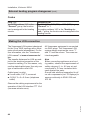
Making the LON connection
The Viessmann LON system is designed
for the "Line" BUS topology with a terminator at both ends (accessories). For further information, see the "Viessmann
LON manual" at www.viessmann.de/
lon.
The transfer distances for LON are subject to the electrical properties of the
respective cabling. For this reason, only
use the stated cable types. Use only one
type of cable within one LON.
Cable types (on site):
■ 2-core cable, CAT 5, screened
■ JY(St)Y 2 x 2 x 0.8 mm (telephone
cable)
All Viessmann equipment is connected
via RJ45 plugs. The Viessmann LON
system always requires the cores "1"
and "2" and the screen. The cores are
interchangeable.
Note
When connecting appliances and routing cables, observe the requirements of
safety category II, i.e. 8.0 mm air and
creep path or 2.0 mm insulation thickness against live parts.
Ensure safe electrical separation for all
on-site components (incl. PC/laptops) to
ensure conformity to EN 60 335 and
IEC 65.
5815 091 GB
Observe the cabling requirements for the
operation of the LON interface FTT 10-A
(see www.echelon.com).
44
Installation, Vitotronic 300-K
Making the LON connection (cont.)
Connection with Viessmann LON cable
A
A
A
C
C
B
B
Installation spacing ≤ 7 m
C Terminator
Installation
A Control unit or Vitocom
B LON cable, 7 m long
Connection with Viessmann LON cable and coupling
A
A
A
C
C
B D
B D B
B D
B D B
Installation spacing 7 to 21 m
A Control unit or Vitocom
B LON cable, 7 m long
Max. 3 cables between two appliances
C Terminator
D LON coupling
Connection with on-site cable and LON plug
A
A
D
D
E
D
A
D
C
C
B
B
≤ 900 m
5815 091 GB
Installation spacing ≤ 900 m (with LON plug)
A Control unit or Vitocom
B On-site cable
45
Installation, Vitotronic 300-K
Making the LON connection (cont.)
C Terminator
D LON plug
E Up to 30 subscribers
Connection with LON cable, on-site cable and LON socket
A
D
C
F
A
D
D
B
D
C
B
E
A
B
B
E
≤ 900 m
Installation spacing ≤ 900 m (with LON sockets)
D LON sockets
E On-site cable
F Up to 30 subscribers
5815 091 GB
A Control unit or Vitocom
B LON cable, 7 m long
C Terminator
46
Power supply of the Vitotronic 100 and Vitotronic 300-K
Power supply
Regulations
Connect the power supply and implement all safety measures (e.g. RCD circuit) in accordance with IEC 60364, the
connection requirements of your local
power supply utility, and VDE or national
regulations.
Protect the power cable to the control
unit with an appropriate fuse/MCB.
Recommended power cable
3-core cable selected from the following
options:
■ H05VV-F3G 1.5 mm2
■ H05RN-F3G 1.5 mm2
5815 091 GB
For oil and gas combustion equipment
over 100 kW, according to the Sample
Combustion Ordinance "FeuVO", an
"emergency stop" must be installed on
site outside the installation room.
Observe the national combustion equipment ordinance for your region. For combustion equipment to EN 50156-1, the
"emergency stop" installed on site must
comply with the requirements of
EN 50156-1.
Install the "emergency stop" outside the
installation room; it must be able to separate all non-earthed conductors simultaneously with at least 3 mm contact
separation.
We additionally recommend installing an
AC/DC-sensitive RCD (RCD class B
) for DC (fault) currents that can occur
with energy efficient equipment.
47
Installation
Directives
Power supply of the Vitotronic 100 and Vitotronic 300-K
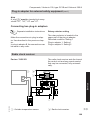
Power supply (cont.)
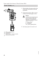
1. Check whether the power cable to the
control unit is protected in line with
regulations.
L1
PE
N
BU
GNYE
BN
2. Terminate the power cable in the terminal box and at plug fÖ (on site).
N
L
40
3. Insert plug fÖ into the control unit.
Mains voltage 230 V~
Fuse/MCB
Mains isolator, 2-pole (on-site)
Junction box (on-site)
5815 091 GB
A
B
C
D
Danger
Incorrect wire assignment can
result in serious injury and
damage to the appliance.
Take care not to interchange
wires "L1" and "N":
L1 BN (brown)
N BU (blue)
PE GNYE (green/yellow)
48
Power supply of the Vitotronic 100 and Vitotronic 300-K
Power supply (cont.)
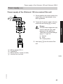
Power supply of the Vitotronic 100 via a mains filter unit
1. Check whether the power cable to the
mains filter unit is protected in line
with regulations.
L1
PE
N
N
L
40
3. Insert plug fÖ into the mains filter
unit.
Mains voltage 230 V~
Fuse/MCB
Mains isolator, 2-pole (on-site)
Junction box (on-site)
5815 091 GB
A
B
C
D
Danger
Incorrect wire assignment can
result in serious injury and
damage to the appliance.
Take care not to interchange
wires "L1" and "N":
L1 Brown
N Blue
PE Green/yellow
49
Installation
BU
GNYE
BN
2. Terminate the power cable in the terminal box and at plug fÖ (on site).
Power supply of the Vitotronic 100 and Vitotronic 300-K
Power supply (cont.)
4. Insert plug fÖ and plug aBH of the
mains filter unit connecting cable into
the appropriate control unit socket.
E
BK
GNYE
GY
BN
fÖ aBH
F
aBH
156
40
fÖ
G
E To the mains filter unit
F Mains filter unit connecting cable
G To the control unit
5815 091 GB
Colour coding to DIN/IEC 60757
BN
Brown
BK
Black
GY
Grey
GNYE Green/yellow
50
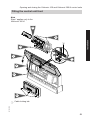
Opening and closing the Vitotronic 100 and Vitotronic 300-K control units
Fitting the control unit front
Note
Step 1 applies only to the
Vitotronic 300-K.
3.
Installation
2.
A
1.
7.
5.
4.
6.
8.
5815 091 GB
A Cable locking tab
51
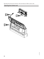
Opening and closing the Vitotronic 100 and Vitotronic 300-K control units
Opening the control unit
2.
1.
5815 091 GB
3.
52
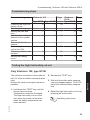
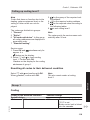
Commissioning, Vitotronic 100 and Vitotronic 300-K
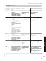
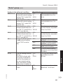
Commissioning steps
Commissioning step
Checking the high limit
safety cut-out
Selecting the language
Setting the date and
time
Matching the coding addresses to the system
version
Selecting the boiler sequence
Connecting the control
unit to the LON
Checking actuators and
sensors
Setting the heating
curve
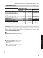
Vitotronic 100
Page
Type GC1B Type GC4B
X
—
Vitotronic
Page
300-K
Type MW1B
53
—
—
—
—
—
—
—
—
X
X
54
54
X
X
54
X
56
—
—
—
X
57
X
X
58
X
58
X
X
61
X
62
—
—
—
X
64
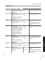
Testing the high limit safety cut-out
Only Vitotronic 100, type GC1B
3. Wait until the boiler water temperature has dropped approx. 15 to 20 K
below the selected safety temperature.
4. Reset the high limit safety cut-out by
pressing the reset button.
Operating instructions
5815 091 GB
1. Hold down the "TEST" key until the
burner has shut down:
Temperature controller is bridged.
The high limit safety cut-out must
shut down the burner at the latest
when the safety temperature has
been reached.
2. Release the "TEST" key.
53
Service
The minimum circulation volume should
be 10 % of the circulation volume at rated
load.
Reduce the heat consumption as far as
possible.
Commissioning, Vitotronic 100 and Vitotronic 300-K
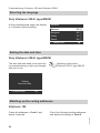
Selecting the language
Only Vitotronic 300-K, type MW1B
At the commissioning stage, the display
is in German (factory setting).
Sprache
Deutsch
ç
DE ê
Bulgarski
BG ê
Cesky
CZ ê
Dansk
DK ê
Wählen mit
(
Setting the date and time
Only Vitotronic 300-K, type MW1B
The time and date need to be reset during commissioning or after a prolonged
time out of use.
Operating instructions
Vitotronic 300-K, type MW1B
Setting
time and date
Continue with
OK
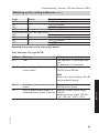
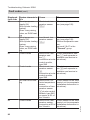
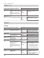
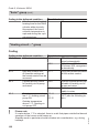
Matching up the coding addresses
Vitotronic 100
Check the following coding addresses
and adjust accordingly in Code 2:
5815 091 GB
Check all addresses in Code 1 and
adjust if required.
54
Commissioning, Vitotronic 100 and Vitotronic 300-K
Matching up the coding addresses (cont.)
Code
Group
Function
"01"
2
Multi boiler system
"4d"
1
Plug sL function
"98"
1
Viessmann system number
"9C"
1
Monitoring LON subscribers
Only for the Vitotronic 100, type GC1B:
"0C"
2
Return temperature control
"0d"
2
Therm-Control
"4C"
1
Plug sÖ function
"4E"
1
Plug gS function
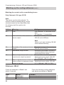
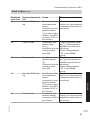
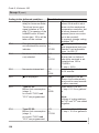
Matching the control unit to a two-stage burner
Only Vitotronic 100, type GC1B
Address
03:...
Meaning
Fuel
08:...
Units and tens of the maximum
burner output
Setting
Gas operation: 0 (delivered condition)
Oil operation: 1 (irreversible)
Example: maximum burner output:
225 kW, set to 25 here.
09:...
Example: maximum burner output:
225 kW, set to 2 here.
Example: Output burner stage 1
135 kW
maximum burner output: 225 kW
(135 : 225) kW∙ 100 % = 60 %
5815 091 GB
0A:...
Hundreds of the maximum burner
output
Ratio of output burner stage 1 to
maximum burner output in percent
55
Service
Note
Values up to and including 199 kW
can be entered directly.
Commissioning, Vitotronic 100 and Vitotronic 300-K
Matching up the coding addresses (cont.)
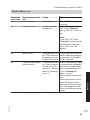
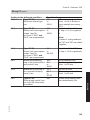
Matching the control unit to a modulating burner
Only Vitotronic 100, type GC1B
Note
The burner must be fully adjusted. To
achieve a wide modulating range, set the
minimum output as low as possible (take
the chimney and flue system into
account).
Address
03:...
Meaning
Fuel
08:...
Units and tens of the maximum
burner output
Setting
Gas operation: 0 (delivered condition)
Oil operation: 1 (irreversible)
Example: maximum burner output:
225 kW, set to 25 here.
Note
Values up to and including 199 kW
can be entered directly.
09:...
15:...
0A:...
05:...
Hundreds of the maximum burner
output
Modulation range runtime
Example: maximum burner output:
225 kW, set to 2 here.
Determine the actuator runtime in
seconds between base load and
maximum burner output.
Ratio of output base load to maxi- Example: Base load output 72 kW
mum burner output in percent
Maximum burner output: 225 kW
(72 : 225) kW ∙ 100 % = 32 %
Ratio of partial load at ⅓ of the ac- Example: Partial output 171 kW
tuator runtime to maximum burner Maximum burner output: 225 kW
output in percent
(171 : 225) kW ∙ 100 % = 76 %
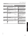
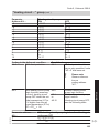
Vitotronic 300-K
Code
"39"
"3A"
56
Group
"Cascade"
"Cascade"
Check the following coding addresses
and adjust accordingly in Code 2:
Function
Permanent lead boiler
Permanent last boiler
5815 091 GB
Check all addresses in Code 1 and
adjust if required.
Commissioning, Vitotronic 100 and Vitotronic 300-K
Matching up the coding addresses (cont.)
Code
"4C"
"4d"
"4E"
"55"
"7A"
"98"
"9C"
Group
"General"
"General"
"General"
"DHW"
"General"
"General"
"General"
Function
Plug sÖ function
Plug sL function
Plug gS function
Cylinder temperature control function
Central control
Viessmann system number
Monitoring LON subscribers
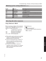
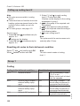
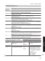
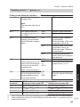
Selecting the boiler sequence
Only Vitotronic 300-K
Boiler sequence subject to the selected
codes in the "Cascade" group and calculations by the control unit:
"38"
Changing the lead boiler
and the boiler sequence
"39"
Permanent lead boiler
"3A"
Permanent last boiler
"41" to "44" ECO thresholds
Extended menu:
1.
2. "Boiler sequence"
3. Select the required boiler sequence.
OK to confirm
5815 091 GB
Service
■ Every boiler can be blocked or enabled
subject to outside temperature by
means of the ECO threshold.
■ The ECO threshold has no effect if a
boiler is required to achieve the set
flow temperature in the case of enabled boilers failing.
■ At least the lead boiler remains in
operation when all boilers in a system
would otherwise be blocked via the
ECO threshold.
57
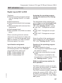
Commissioning, Vitotronic 100 and Vitotronic 300-K
Connecting the control unit to the LON
■ A LON communication module must
be fitted into every Vitotronic 100 (see
page 18).
Installation and service instructions Vitotronic 200-H
■ Within one LON, each subscriber
number must only allocated once.
■ Within a single LON, the system number (coding address "98" in the "General" group) must always be the same.
■ Only one Vitotronic may be programmed as fault manager.
■ The data transfer via LON can take
several minutes.
Note
The LON communication module is an
integral part of the Vitotronic 300-K.
■ Vitotronic 200-H:
The LON communication module
(accessory) must be fitted.
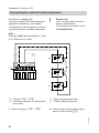
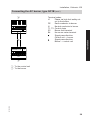
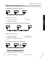
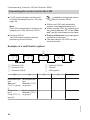
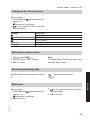
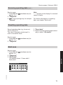
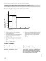
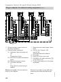
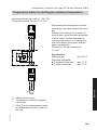
Example of a multi boiler system
A Vitotronic 100
B Vitotronic 100
C Vitotronic 300-K
E
LON
D
LON
LON
C
LON
LON
B
LON
LON
A
LON
F
D Vitotronic 200-H
E Vitocom
F LON system
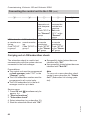
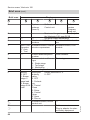
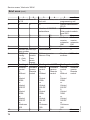
A
B
Multi boiler system
Set code
"01:2" in group
2
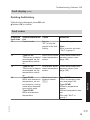
Boiler number 1
Code "07:1" in
group 2
Multi boiler system
Set code "01:2"
in group 2
C
D
E
—
—
Boiler number 2 —
Set code "07:2"
in group 2
—
—
5815 091 GB
—
58
Commissioning, Vitotronic 100 and Vitotronic 300-K
Connecting the control unit to the LON (cont.)
B
With LON communication
module.
Code "76:1" in
group 1 recognised automatically
With LON communication
module.
Code "76:1" in
group 1 recognised automatically
C
Control unit is
not fault manager.
Code "79:0" in
group 1
With LON
communication module.
Code "76:1" in
the "General"
group recognised automatically
—
Number of
connected
boilers.
Set codes
"35:1" to
"35:4" in the
"Cascade"
group
Subscriber
Subscriber
no. 2.
no. 5.
Set code "77:2" Code "77:5" in
in group 1
the "General"
group
Control unit is
Control unit is
not fault manag- fault manager.
er.
Code "79:1" in
Code "79:0" in
the "General"
group 1
group.
—
—
—
E
With LON
—
communication module.
Code "76:1" in
the "General"
group recognised automatically
—
—
Subscriber
no. 10.
Code "77:10"
in the "General" group
Control unit is
not fault manager.
Code "79:0" in
the "General"
group.
Control unit
The control
transmits the
unit receives
time.
the time.
Code "7b:1" in Set code
the "General" "81:3" in the
group
"General"
group
Subscriber
no. 99
Device is fault
manager
Device receives the time
5815 091 GB
Subscriber
no. 1.
Code "77:1" in
group 1
D
59
Service
A
Commissioning, Vitotronic 100 and Vitotronic 300-K
Connecting the control unit to the LON (cont.)
A
—
B
—
C
D
E
Control unit
transmits outside temperature.
Code "97:2" in
the "General"
group
Control unit
—
receives the
outside temperature.
Set code
"97:1" in the
"General"
group
LON subscrib- LON subscriber LON subscrib- LON subscrib- —
er remote mon- remote monitor- er remote
er remote
itoring.
ing.
monitoring.
monitoring.
Code "9C:20"
Code "9C:20" in Code "9C:20" Code "9C:20"
in group 1
group 1
in the "Gener- in the "General" group
al" group
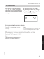
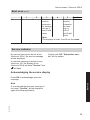
Carrying out a LON subscriber check
The subscriber check is used to test
communication with the system devices
connected to the fault manager.
Preconditions:
■ The control unit must be programmed
as fault manager (code "79:1" in the
"General" group).
■ The LON subscriber number must be
programmed in all control units.
■ The LON subscriber list in the fault
manager must be up to date.
■ Successfully tested subscribers are
identified with "OK".
■ Unsuccessfully tested subscribers are
identified with "Not OK".
Note
To carry out a new subscriber check,
create a new subscriber list: "Delete
list?" (Subscriber list is being updated).
5815 091 GB
Service menu:
1. Press OK and
simultaneously for
approx. 4 s.
2. "Service functions"
3. "Subscriber check"
4. Select subscriber (e.g. subscriber 10).
5. Start the subscriber check with "OK".
60
Commissioning, Vitotronic 100 and Vitotronic 300-K
Connecting the control unit to the LON (cont.)
Note
■ Vitotronic 100:
During the subscriber check, the display for the relevant subscriber flashes
for approx. 1 min.
■ Vitotronic 200-H:
During the subscriber check, the display for the relevant subscriber flashes
the subscriber no. for approx. 1 min
and displays "Wink".
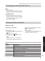
Checking actuators and sensors
Vitotronic 100
Carrying out a relay test
Service menu:
1. Press OK and å simultaneously for
approx. 4 s.
flashes on the display.
2. Press to select . OK to confirm
3. / for the required actuator (output),
see the following table.
4. OK to confirm
The display shows the number for the
activated actuator and "ON".
5815 091 GB
The following relay outputs can be controlled subject to the system equipment
level:
Display
Explanation
0
All actuators have been switched off.
Stepped burner:
1
Burner ON or burner stage 1 ON
2
Burner stage 1 and 2 ON
Modulating burner:
1
Modulation controller open
2
Modulation controller neutral
3
Modulation controller close
5
Actuator at output sÖ on
61
Service
Note
Before an actuator is selected, all
actuators are switched to zero volt.
Commissioning, Vitotronic 100 and Vitotronic 300-K
Checking actuators and sensors (cont.)
Display
6
7
8
9
11
Explanation
Actuator at output sL on
Actuator at output gS open
Actuator at output gS neutral
Actuator at output gS close
Central fault message at output gÖ on
Note
Connected pumps start during burner
operation.
Checking sensors
Actual temperatures can be scanned in
menu .
Operating instructions
Vitotronic 300-K
Carrying out a relay test
Service menu:
1. Press OK and
approx. 4 s.
2. "Actuator test"
simultaneously for
The following relay outputs can be controlled subject to the system equipment
level:
Display
Explanation
"All actuators"
OFF
All actuators have been switched off.
"Output 20"
ON
Actuator at output sÖ A1
"Output 52"
Open
Actuator at output gS A1
"Output 52"
Neutral
"Output 52"
Close
"Cylinder primary
ON
Actuator at output sÖ
pump"
"DHW circ pump"
ON
Actuator at output sA
"Output 29"
ON
Actuator at output sL
62
5815 091 GB
Note
Before an actuator is selected, all
actuators are switched to zero volt.
Commissioning, Vitotronic 100 and Vitotronic 300-K
Checking actuators and sensors (cont.)
ON
ON
Explanation
Central fault message at output gÖ
Actuator at output sÖ M2
Open
Close
ON
Actuator at output gS M2
Open
Close
ON
Actuator at output gS M3
"AM1 output 1"
"AM1 output 2"
"Solar circuit pump"
ON
ON
ON
"Solar circ pmp min"
ON
"Solar circ pmp max"
ON
"SM1 output 22"
ON
Actuator at output sÖ M3
Contact " P - S" on plug aBJ of extension EA1
closed.
Actuator at output A1
Actuator at output A2
Solar circuit pump at output sF at solar control module type SM1
Solar circuit pump at output sF at solar control module type SM1 switched to minimum
speed.
Solar circuit pump at output sF at solar control module type SM1 switched to maximum
speed.
Actuator at output sS at solar control module
type SM1
Information regarding the mixer
motor rotational direction
The flow temperature must rise when the
mixer opens. If the temperature drops,
either the motor is turning in the wrong
direction or the mixer set is incorrectly
fitted (observe the mixer installation
instructions).
3. / for the required group (see overview on page 70)
4. / for the actual temperature of the
required sensor
Service
Display
"Central fault mess."
"Heating circ pump
HC2"
"Mixer HC2"
"Mixer HC2"
"Heating circ pump
HC3"
"Mixer HC3"
"Mixer HC3"
"EA1 output 1"
5815 091 GB
Checking sensors
Service menu:
1. Press OK and
approx. 4 s.
2. "Diagnosis"
simultaneously for
63
Commissioning, Vitotronic 100 and Vitotronic 300-K
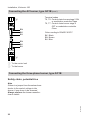
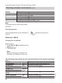
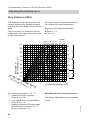
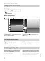
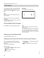
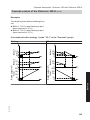
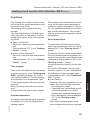
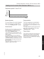
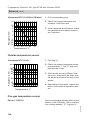
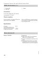
Adjusting the heating curve
Only Vitotronic 300-K
The heating curves represent the relationship between the outside temperature and the boiler water or flow temperature.
To put it simply, the lower the outside
temperature, the higher the boiler water
or flow temperature.
The boiler water or flow temperature in
turn affects the room temperature.
Settings in the delivered condition:
■ Slope = 1.4
■ Level = 0
1.8
100
1.6
80
1.2
70
1.0
60
0.8
50
0.4
30
0.2
0
For outside temperature −14 °C
A Underfloor heating system
Slope 0.2 to 0.8
B Low temperature central heating
Slope 0.8 to 1.6
C Heating systems with boiler water
temperature in excess of 75 °C
Slope in excess of 1.6
64
B
0.6
40
3
Se 0 2
t ro
5
om
10 5
tem 20
per 15
atu
1
re
in ° 0 5
C
C
1.4
-5
A
-10 -15 -20 -25 -30
Outside temperature in °C
Selecting the set room temperature
Individually adjustable for each heating
circuit.
5815 091 GB
Boiler water or
flow temperature in °C
90
35
2.0
110
2.2
3.4
3.2
3.0
2.8
2.6
2.4
Slope
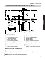
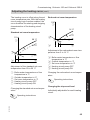
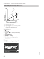
Commissioning, Vitotronic 100 and Vitotronic 300-K
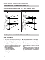
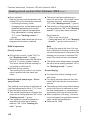
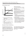
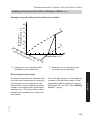
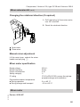
Adjusting the heating curve (cont.)
The heating curve is offset along the set
room temperature axis. With the heating
circuit pump logic function enabled, the
curve modifies the starting and stopping
characteristics of the heating circuit
pump.
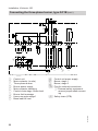
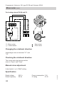
Reduced set room temperature
110
A
14 °C
Standard set room temperature
26 °C
20 °C
C 26
D
20
C
D
3 °C
20
14
3
B -20
E
Adjustment of the reduced set room temperature from 3 to 14 °C
B -20
E
Adjustment of the standard set room
temperature from 20 to 26 °C
A Boiler water temperature or flow
temperature in °C
B Outside temperature in °C
C Set room temperature in °C
D Heating circuit pump OFF
E Heating circuit pump ON
A Boiler water temperature or flow
temperature in °C
B Outside temperature in °C
C Set room temperature in °C
D Heating circuit pump OFF
E Heating circuit pump ON
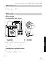
Changing the reduced set room temperature
Operating instructions
Changing the slope and level
Changing the standard set room temperature
Individually adjustable for each heating
circuit.
5815 091 GB
Operating instructions
65
Service
110
A
Commissioning, Vitotronic 100 and Vitotronic 300-K
Adjusting the heating curve (cont.)
110
Boiler water or
Flow temperature in °C
3.4
1.4
A
B
0.2
+20
-20
Outside temperature in °C
A Changing the slope
B Changing the level (vertical parallel
offset of the heating curve)
Extended menu:
1.
2. "Heating"
3. Possibly / for the required heating
circuit
4. "Heating curve"
5. "Slope" or "Level"
6. Set values according to system
requirements.
Example:
Heating curve setting with slope 1.5:
Heating curve
HC1
100 °C
23 °C
41 °C
20
Slope
10
-10
-20
-30
1.5
(
5815 091 GB
Change with
0
81 °C
68 °C
55 °C
66
Service scans, Vitotronic 100
Calling up the service menu
Service menu:
1. Press OK and
simultaneously for
approx. 4 s.
flashes on the display.
2. / for the required function (see the
following table).
Symbol
Code 1
Code 2
Function
Diagnosis
Relay test
Fault history
Coding level 1
Coding level 2
Exiting the service menu
1. With select SERV 7.
2. OK to confirm; "OFF" flashes.
3. OK to confirm
Note
The system exits the service menu automatically after 30 min.
Scanning operating data
Operating instructions
Brief scan
3. / for the required function (see the
following table).
4. OK to confirm
5815 091 GB
Service menu:
1. Press OK and
simultaneously for
approx. 4 s.
flashes on the display.
2. OK to confirm
67
Service
Operating data can be scanned in menu
.
Service scans, Vitotronic 100
Brief scan (cont.)
0
2
3
6
7
8
9
b
L
E
1
E
3
68
Display
—
System
scheme
(here 0)
Software version
Control unit
Software
version
Programming unit
—
—
Maximum flue gas temperature; only for
the Vitotronic 100, type GC1B
—
—
Set boiler water temperature
—
Number of KM BUS sub- Number of LON subscribscribers
ers
SNVT con- Software version, commu- Software version, LON
figuration
nication coprocessor
module
0: Auto
1: Tool
—
Subnet address/system
Node address
number
—
Burner control unit/burner Device type
type
0: Single stage
1: Two-stage
2: Modulating
—
Boiler coding card
Burner:
Motorised
Output reduction in %
0: OFF
butterfly
0: OFF
1: Burner
valve:
stage 1/
0: OFF
base load
1: Preheat2: Burner
ing
stage 2/full 2: Control
load
Close
3: Rules
4: Control
Open
5: Open
6: Run-on
—
Software version, burner
—
control unit
Software version
Plug-in adaptor for external safety equipment
5815 091 GB
Brief scan
Service scans, Vitotronic 100
Service indicator
After the limits set at coding address
"1F", "21", "23" in group 2 have been
reached, the red fault indicator begins to
flash and the display shows the following
messages:
■ The specified hours run and .
■ The specified interval with and .
■ The specified maximum flue gas temperature and ; only for the
Vitotronic 100, type GC1B.
a
150
°C
Acknowledging the service display
Press OK to acknowledge a service
message.
Note
An acknowledged service message that
was not reset reappears after 7 days.
After a service has been carried out (resetting service)
Reset code "24:1" in group 2 to "24:0".
5815 091 GB
Service
Note
The selected service parameters for
hours run and interval restart at 0.
69
Service scans, Vitotronic 300-K
Calling up the service menu
Service menu:
1. Press OK and
simultaneously for
approx. 4 s.
2. / for the required menu (see the following diagram).
Service menu overview
Service
Diagnosis
Actuator test
Coding level 1
Coding level 2
Fault history
Service functions
Terminate service?
"Coding level 2" is only displayed if this
level has been enabled:
General
Heating circuit 1
Heating circuit 2
Heating circuit 3
DHW
Solar
Brief scan
Reset data
HC1
HC2
HC3
Subscriber check
Service PIN
Enter Vitocom PIN code
Service reset
Press OK and
approx. 4 s.
simultaneously for
Exiting the service menu
Service menu:
1. "Terminate service?"
2. "Yes"
Note
The system exits the service menu automatically after 30 min.
Operating data can be scanned in six
areas (see "Diagnosis" in the "Service" menu overview).
70
Operating data on heating circuits with
mixers and a solar thermal system can
only be scanned if the relevant components are installed in the system.
5815 091 GB
Scanning operating data
Service scans, Vitotronic 300-K
Scanning operating data (cont.)
Service menu:
1. Press OK and
simultaneously for
approx. 4 s.
2. "Diagnosis"
3. / for the required group, for example
"General".
Note
"- - -" appears on the display if a scanned
sensor is faulty.
For further information on operating
data, see chapter "Brief scan".
Resetting operating data
Saved operating data (e.g. hours run)
can be reset to 0.
The value "Adjusted outside temp" is
reset to the actual value.
Service menu:
1. Press OK and
approx. 4 s.
2. "Diagnosis"
3. "Reset data"
4. Select required operating data individually or select "All details".
simultaneously for
Brief scan
Service
Service menu:
1. Press OK and
simultaneously for
approx. 4 s.
2. "Diagnosis"
3. "Brief scan"
The display shows 11 lines with 6
fields each.
Diagnosis brief scan
0
0
0
0
1
0
0
0
0
0
0
0
A
A
0
0
A
1
0
0
5815 091 GB
Select with
0
0
0
0
Ø
1:
2:
3:
4:
71
Service scans, Vitotronic 300-K
2:
1
2
System schemes 01
to 10
0
0
3
4
Software version, control unit
0
3:
0
0
Number of KM BUS
subscribers
4:
5:
0
0
0
0
0
0
6:
7:
0
0
Subnet address/system number
SNVT
Software
config.
version
0: Auto
Com1: Tool
munic.
coproc.
Heating circuit HC1
Remote
Software
control
version
0:
Remote
Without
control
1:
Vitotrol
200A
or
Vitotrol
200 RF
2:
Vitotrol
300A
or
Vitotrol
300 RF
or
Vitohome
300
0
0
1:
8:
9:
10:
72
0
0
Node address
5
6
Software version,
programming unit
Device identification
ZE-ID
Software version
Solar control module,
type SM1
0
0
Software Software
version,
version,
extension extension
AM1
EA1
0
0
0
0
Software version
Neuron Chip
Number of LON subscribers
Heating circuit HC2
Remote
Software
control
version
0:
Remote
Without
control
1:
Vitotrol
200A
or
Vitotrol
200 RF
2:
Vitotrol
300A
or
Vitotrol
300 RF
or
Vitohome
300
0
0
Heating circuit HC3
Remote
Software
control
version
0:
Remote
Without
control
1:
Vitotrol
200A
or
Vitotrol
200 RF
2:
Vitotrol
300A
or
Vitotrol
300 RF
or
Vitohome
300
0
0
0
0
5815 091 GB
Brief scan (cont.)
Service scans, Vitotronic 300-K
Brief scan (cont.)
1
11:
0
2
0
3
Software
0
version,
extension
for heating
circuits 2
and 3 with
mixer
4
5
Software 0
version,
extension
for heating circuits 2
and 3 with
mixer
6
Note
The displays in fields 3 and 5 are the same.
Service indicator
No service interval can be set at the
Vitotronic 300-K. No service message
will be displayed.
If a service message is active on any
Vitotronic 100, the display of the
Vitotronic 300-K will show "Service" and
will flash.
Confirm with OK. "Subscriber service" will be shown.
Acknowledging the service display
Press OK to acknowledge a service
message.
5815 091 GB
Service
Note
If an acknowledged service message is
not reset, "Service" will be displayed
again the following Monday.
73
Troubleshooting Vitotronic 100
Fault display
In the event of a fault, the red fault indicator flashes at the control unit. The 2digit fault code and flash on the display.
Note
Any connected central fault message
facility starts.
Example:
Fault code "d1" burner fault
ã
1
d1
Other current faults can be displayed
with / .
For an explanation of the fault code, see
chapter "Fault codes".
Acknowledging fault messages
Press OK; the default display appears.
Note
Any connected central fault message
facility stops.
If an acknowledged fault is not remedied,
the fault message will be re-displayed
the following day and the fault message
facility restarted.
Calling up acknowledged faults
Hold down OK for approx. 4 s.
Calling up fault codes from the fault memory (fault history)
The 10 most recent faults (including
those remedied) are saved and can be
called up.
Faults are sorted by date.
3. With select ã and activate fault history with OK.
4. / for the required fault message
5815 091 GB
Service menu:
1. Press OK and
simultaneously for
approx. 4 s.
flashes on the display.
2. OK to confirm
74
Troubleshooting Vitotronic 100
Fault display (cont.)
Deleting fault history
While the list is displayed, press OK until
flashes. OK to confirm.
Fault codes
30
38
Type GC1B:
The burner is started
and stopped via the
temperature controller.
Type GC1B:
The burner is started
and stopped via the
temperature controller.
Type GC1B:
Boiler with maximum
temperature, no output reduction, mixing
valve return temperature control open
Type GC4B:
Boiler at maximum
temperature
Measures
Service the appliance.
Note
After a service set code
"24:0" in group 2.
Short circuit, boiler Check boiler water temwater temperature perature sensor (see
sensor
page 185).
Lead break, boiler
water temperature
sensor
Check boiler water temperature sensor (see
page 185).
Short circuit, temperature sensor
aJA
Type GC1B
Check temperature sensor (see page 185).
Type GC4B:
Remove temperature
sensor.
Without temperature sensor:
Set code "4A:0" in
group 1.
5815 091 GB
60
System characteris- Cause
tics
Control mode
Service
"0F" is only displayed in the fault
history.
75
Service
Displayed
fault code
0F
Troubleshooting Vitotronic 100
Fault codes (cont.)
System characteristics
Type GC1B:
Boiler with maximum
temperature, no output reduction, mixing
valve return temperature control open
Type GC4B
Boiler at maximum
temperature
70
Type GC1B:
Shunt pump constantly ON.
Type GC4B:
Control mode
78
Type GC1B:
Shunt pump constantly ON.
Type GC4B:
Control mode
A0
Boiler cools down.
A1
Boiler cools down.
76
Cause
Measures
Lead break, temperature sensor
aJA
Type GC1B
Check temperature sensor (see page 185).
Type GC4B:
Remove temperature
sensor.
Without temperature sensor:
Set code "4A:0" in
group 1.
Short circuit, tem- Type GC1B:
perature sensor
Check temperature sensor (see page 185).
aJB
Type GC4B:
Remove temperature
sensor.
Without temperature sensor:
Set code "4b:0" in
group 1.
Lead break, temType GC1B:
perature sensor
Check temperature sensor (see page 185).
aJB
Type GC4B:
Remove temperature
sensor.
Without temperature sensor:
Set code "4b:0" in
group 1.
Fault, safety equip- Check safety equipment,
ment at "X7" of
and reset if required.
plug-in adaptor 2
for external safety
equipment
Fault, safety equip- Check safety equipment,
ment at "X3" of
and reset if required.
plug-in adaptor 2
for external safety
equipment
5815 091 GB
Displayed
fault code
68
Troubleshooting Vitotronic 100
Fault codes (cont.)
A3
AA
AC
Ad
b0
Measures
Check safety equipment,
and reset if required.
Check safety equipment,
and reset if required.
Insert plug aJA.
For the Vitocrossal code
"0d:0" in group 2 must be
set.
Insert plug aJA and
check codes.
With motorised butterfly
valve:
set code "4E:0" in
group 1.
Without motorised butterfly valve:
set code "0C:1" in
group 2.
Check the flue gas temperature sensor (see
page 186).
Check connections, and
replace the programming
unit if required.
5815 091 GB
b1
System characteris- Cause
tics
Boiler cools down.
Fault, safety equipment at "X2" of
plug-in adaptor 2
for external safety
equipment
Boiler cools down.
Fault, safety equipment at "X1" of
plug-in adaptor 2
for external safety
equipment
Type GC1B:
Configuration fault,
Control mode
Therm-Control:
Plug aJA not
plugged in.
Type GC1B:
Configuration fault,
Control mode
return temperature
control:
Code "0C:1" in
group 2 is set, but
plug aJA is not
plugged in and/or
code "4E:0" in
group 1 is not set.
Control mode
Configuration fault,
motorised butterfly
valve:
code "0C:2", "0C:
3" or "0C:4" in
group 2 is set
and
code "4E:1" in
group 1 is set.
Type GC1B:
Short circuit, flue
Control mode
gas temperature
sensor
Control mode
Communication error, programming
unit
77
Service
Displayed
fault code
A2
Troubleshooting Vitotronic 100
Fault codes (cont.)
Displayed
fault code
b5
System characteris- Cause
tics
Control mode
Internal error
b6
Constant mode
Invalid hardware
recognised
Measures
Check PCB and plug-in
connection; replace PCB
if required.
Check coding address
"92" in group 1:
Type GC1B: "92:161"
Type GC4B: "92:166"
Note
Code "8A:176" in the
group 1 must be set for
coding address "92" to be
displayed.
b7
b8
bF
Boiler coding card
fault
Plug in or replace boiler
coding card.
Lead break, flue
gas temperature
sensor
Control mode
No communication
via LON
Boiler cools down.
Incorrect LON
communication
module
External safety
equipment on
plug aBÖ
Check the flue gas temperature sensor (see
page 186).
Without flue gas temperature sensor:
set code "1F:0" in
group 2.
Replace LON communication module.
Check connection and external safety equipment.
5815 091 GB
C1
Type GC1B:
Regulating the boiler
water temperature to
that set at the temperature controller
Type GC4B:
Regulating the boiler
water temperature to
the electronic maximum temperature
limit (code "06")
Type GC1B:
Control mode
78
Troubleshooting Vitotronic 100
Fault codes (cont.)
C9
CA
Cb
5815 091 GB
CE
System characteris- Cause
tics
Boiler cools down.
Fault, low water indicator at "X7" of
plug-in adaptor 1
for external safety
equipment
Boiler cools down.
Fault, maximum
pressure limiter at
"X3" of plug-in
adaptor 1 for external safety equipment
Boiler cools down.
Fault, minimum or
maximum pressure limiter 2 at
"X2" of plug-in
adaptor 1 for external safety equipment
Boiler cools down.
Additional high limit safety cut-out
fault
Or
Temperature limiter at "X1" of plug-in
adaptor 1 for external safety equipment
Control mode
Communication error, plug-in adaptor
1 for external safety equipment
CF
Control mode
No communication
via LON.
d1
Boiler cools down.
Measures
Check the water level in
the system; reset low water indicator (see
page 187).
Check the system pressure; reset maximum
pressure limiter (see
page 187).
Check the system pressure; reset minimum or
maximum pressure limiter 2 (see page 187).
Check the system temperature; reset high limit
safety cut-out (see
page 187).
Check the plug-in adaptor
(see page 187).
Without plug-in adaptor:
Set code "30:0" in
group 1.
Communication er- Check LON communicaror, control unit
tion module and replace if
LON communica- required.
tion module
If no LON communication
module is installed, set
code "76:0" in group 1.
Burner fault
Check the burner.
79
Service
Displayed
fault code
C8
Troubleshooting Vitotronic 100
Fault codes (cont.)
Displayed
fault code
d2
System characteris- Cause
tics
Control mode
Communication error, plug-in adaptor
2 for external safety equipment
d4
Boiler cools down.
Measures
Check the plug-in adaptor
(see page 187).
Without plug-in adaptor:
Set code "31:0" in
group 1.
The high limit safe- Check the high limit safety
ty cut-or MCB/
cut-out or the burner,
fuse F2 has tripburner loop and MCB/
ped/blown.
fuse F2.
Fault codes only for the Vitotronic 100, type GC4B
81
82
83
Burner control unit in
a fault state; system
cools down; burner
control unit locked
out.
Burner control unit in
a fault state.
88
Burner control unit in
a fault state.
89
Burner control unit in
a fault state.
80
Cause
Measures
Short circuit, boiler Check lead and twin senwater temperature sor; replace sensor if resensor, burner
quired.
control unit.
Sensor drift, boiler
water temperature
sensor, burner
control unit.
Short circuit, flue
gas temperature
sensor (A or B),
burner control unit.
Check lead and twin sensor; replace sensor if required.
Sensor drift, flue
gas temperature
sensor (A or B),
burner control unit.
Lead break, boiler
water temperature
sensor, burner
control unit.
Lead break, flue
gas temperature
sensor (A or B),
burner control unit.
Check lead and sensors
(A and B); replace sensor
if required.
Check lead and sensors
(A and B); replace sensor
if required.
Check lead and twin sensor; replace sensor if required.
Check lead and sensors
(A and B); replace sensor
if required.
5815 091 GB
80
System characteristics
Burner control unit in
a fault state; system
cools down; burner
control unit locked
out.
Burner control unit in
a fault state.
Troubleshooting Vitotronic 100
Fault codes (cont.)
E2
E2
E3
E4
E5
EE
EF
Check setting of gas pressure switch 2; check connecting cable; replace gas
train.
Check setting of gas pressure switch 2; check connecting cable; replace gas
train.
Replace gas train.
Check strapping plug fJ.
Check the power supply.
Replace burner control
unit.
Reset burner control unit;
replace burner control
unit.
Reset burner control unit;
replace burner control
unit.
Check plug and KM BUS
to burner control unit.
5815 091 GB
F0
Measures
81
Service
E1
System characteris- Cause
tics
Burner control unit in Valve 1 not tight /
a fault state.
gas pressure
switch 2 does not
open.
Burner control unit in Valve 2 not tight;
a fault state.
gas pressure
switch 2 does not
close.
Shortage of gas to
Gas valve does not
gas pressure switch open; gas valve
2; valve leak test.
leaking; gas pressure switch 2 faulty.
Burner control unit in Lead break, strapa fault state.
ping plug fJ.
Burner shuts down.
Multiple detection
of undervoltage
with recovery and
renewed undervoltage.
Burner control unit in Internal error of the
a fault state.
burner control unit
and during test of
ionisation input.
Burner control unit in Internal error in
a fault state.
feedback from gas
safety valves; output relay does not
respond.
Burner control unit in Internal error in
a fault state.
feedback from gas
safety valves; output relay does not
respond.
Operation according Communication erto internal burner
ror, burner control
control unit defaults. unit.
Troubleshooting Vitotronic 100
Fault codes (cont.)
F1
F2
F3
F4
Cause
Measures
Excessive flue gas
temperature; excessive gas
throughput.
Wait until temperature undershoots the permissible
flue gas temperature. Reset burner control unit.
Check water level; check
heat exchanger surfaces
for contamination; check
CO2 setting; set gas
throughput according to
rated heating output of
boiler (for connection values, see boiler service instructions).
Burner control unit in Excessive boiler
Wait until temperature una fault state; system temperature.
dershoots the permissible
cools down.
boiler water temperature.
Reset burner control unit.
Ionisation flame mon- Gas train not gas- Check ionisation path; reitor reports faulty
tight (gas is escap- place coding card; reflame signal during
ing and burning);
place gas train.
start-up or postincorrect coding
purge.
card.
No flame builds dur- Ionisation elecInsert plug of ionisation
ing safety time; ioni- trode incorrectly
electrode; check cables;
sation flame monitor adjusted; ionisaadjust ionisation elecreports no flame sig- tion electrode not
trode (see boiler service
nal.
plugged in. Earth
instructions).
leakage of electrode or cable.
No flame builds dur- Ignition electrodes Adjust ignition electrodes
ing safety time; ioni- incorrectly adjus(see boiler service insation flame monitor ted, electrodes
structions); replace ignireports no flame sig- shorted out to
tion unit; replace burner
nal.
earth, faulty ignicontrol unit.
tion unit, faulty
burner control unit.
5815 091 GB
F4
System characteristics
Burner control unit in
a fault state; system
cools down.
82
Troubleshooting Vitotronic 100
Fault codes (cont.)
F4
F4
F4
F4
F5
5815 091 GB
F5
Cause
Measures
Insulation body of
ignition or ionisation electrode
cracked.
Replace ignition or ionisation electrode.
Servomotor faulty,
servomotor connecting cable faulty, output relay
faulty (burner control unit).
Flame does not build Incorrect gas type
during the safety
selected.
time, no signal reported by the ionisation
flame monitor.
Flame does not build Gas train does not
during the safety
open.
time, no signal reported by the ionisation
flame monitor.
Flame does not build Combustion charduring the safety
acteristics not idetime, no signal repor- al.
ted by the ionisation
flame monitor.
Air pressure switch
reports no air pressure, fan not running.
Air pressure switch
trips during operation.
Replace connecting cable; replace servomotor;
replace burner control
unit.
Select correct gas type
(see boiler service instructions).
Check connecting cable;
check gas train and replace if required.
Adjust the burner (see
boiler service instructions); if necessary also
adjust the adjusting
screws when the burner is
off to be able to start the
burner.
Air pressure switch Replace air pressure
faulty, incorrectly
switch, connect or set corconnected or incor- rectly.
rectly set.
Flue gas back
Remove flue gas back
pressure; conden- pressure; check if consate banked up; air densate banked up; reset
pressure switch
burner control unit; rehose faulty; conplace hose.
necting hose leaking.
83
Service
F4
System characteristics
No flame builds during safety time; ionisation flame monitor
reports no flame signal.
Poor start-up characteristics; rotary damper does not close.
Troubleshooting Vitotronic 100
Fault codes (cont.)
F6
F7
F7
F8
System characteristics
Gas pressure switch
reports no gas pressure.
Cause
Measures
Gas shut-off valve
closed; gas pressure switch faulty;
multiple problems
with gas supply.
Fan pressure is produced during the air
pressure switch idle
state check.
Air pressure switch
contact is not in the
idle state.
Flame extinguishes
during operation.
Wind influence on
fan.
Open gas shut-off valve;
check gas flow pressure;
replace gas filter if required; reset burner control unit; replace gas
train.
Check the flue draught
(chimney).
F8
Flame extinguishes
during operation.
F8
Flame extinguishes
during operation.
F9
F9
Incorrect gas type
selected.
Burner gauze assembly faulty.
Combustion characteristics not ideal.
Fan not running; fan Fan faulty; cables
speed not reached.
are faulty or broken.
Fan ramp-up
Internal error; fan
cannot reach its set
value.
Fan speed deviation. Fan faulty, cable a-ÖA faulty or
broken.
Select correct gas type
(see boiler service instructions).
Check burner gauze assembly; replace if damaged.
Adjust burner (see boiler
service instructions).
Check cables and replace
the fan if required.
Replace fan or burner
control unit.
Check cable a-ÖA and
external power supply.
Replace cable and fan if
necessary.
5815 091 GB
F9
Air pressure switch Replace the air pressure
faulty.
switch.
84
Troubleshooting Vitotronic 100
Fault codes (cont.)
F9
FA
Measures
Check cable a-ÖA and
external power supply.
Replace cable and fan if
necessary.
Check flue outlet, wind influence on fan and fan itself. Possibly replace
components.
Read off fault at the burner control unit display and
programming unit (boiler
service instructions).
5815 091 GB
Service
Fd
System characteris- Cause
tics
■ Fan faulty.
No fan feedback.
■ Fan may be
blocked by dirt.
■ External fan
power supply not
connected or
faulty.
■ Cable a-ÖA
faulty or broken.
Fan runs without de- Fan does not reach
mand; burner control standstill; caunit in a fault state.
ble a-ÖA faulty,
fan faulty, burner
control unit faulty.
Burner control unit in Burner control unit
a fault state; system in a fault state.
cools down; burner
control unit locked
out.
85
Troubleshooting Vitotronic 300-K
Fault display
In the event of a fault, the red fault indicator flashes at the control unit. "Fault"
is displayed and flashes.
The fault code is displayed with OK.
For an explanation of fault codes, see
chapter "Fault codes".
For some faults, the type of fault is also
displayed in plain text.
Note
Any connected central fault message
facility starts.
Acknowledging fault messages
Follow the instructions on the display.
Note
The fault message is transferred to the
menu.
Any connected central fault message
facility stops.
If an acknowledged fault is not remedied,
the fault message will be re-displayed
the following day at 07:00 h, and the fault
message facility restarts.
Calling up acknowledged fault messages
Extended menu:
1.
2. "Fault"
Calling up fault codes from the fault memory (fault history)
The 10 most recent faults (including
those remedied) are saved and can be
called up.
Faults are sorted by date.
5815 091 GB
Note
The list can be deleted.
86
Troubleshooting Vitotronic 300-K
Fault display (cont.)
Press OK and
approx. 4 s.
simultaneously for
Fault history
Display?
Delete?
Select with
(
Fault codes
18
19
Cause
Measures
Short circuit, outside temperature
sensor
Lead break, outside temperature
sensor
Communication error, wireless outside temperature
sensor
Check outside temperature sensor (see
page 186).
Check outside temperature sensor (see
page 186)
Check wireless connection (place wireless outside temperature sensor
close to the wireless base
station). Log off outside
temperature sensor then
log on again. Replace if
required (see wireless
base station installation
and service instructions).
Standalone control
Short circuit, com- Check the flow temperaunit without flow tem- mon flow tempera- ture sensor (see
perature sensor (flow ture sensor
page 185).
temperature may not
be high enough).
5815 091 GB
20
System characteristics
Operates as if the
outside temperature
was 0 °C.
Operates as if the
outside temperature
was 0 °C.
Operates as if the
outside temperature
was 0 °C.
87
Service
Displayed
fault code
10
Troubleshooting Vitotronic 300-K
Fault codes (cont.)
40
System characteristics
Standalone control
unit without flow temperature sensor (flow
temperature may not
be high enough).
Mixer is being
closed.
44
Mixer is being
closed.
48
Mixer is being
closed.
4C
Mixer is being
closed.
50
Cylinder loading
pump on:
Set DHW temperature = set flow temperature
Priority control is cancelled.
Or
With cylinder loading
system:
Cylinder heating is
started and stopped
via cylinder temperature sensor 2.
88
Cause
Measures
Lead break, com- Check the flow temperamon flow tempera- ture sensor (see
ture sensor
page 185).
Short circuit, flow
temperature sensor, heating circuit
with mixer M2
(heating circuit 2)
Short circuit, flow
temperature sensor, heating circuit
with mixer M3
(heating circuit 3)
Lead break, flow
temperature sensor, heating circuit
with mixer M2
(heating circuit 2)
Lead break, flow
temperature sensor, heating circuit
with mixer M3
(heating circuit 3)
Short circuit, cylinder temperature
sensor 1
Check the flow temperature sensor (see
page 185).
Check the flow temperature sensor (see
page 185).
Check the flow temperature sensor (see
page 185).
Check the flow temperature sensor (see
page 185).
Check cylinder temperature sensor (see
page 185).
5815 091 GB
Displayed
fault code
28
Troubleshooting Vitotronic 300-K
Fault codes (cont.)
58
59
60
Cause
Measures
Short circuit, cylinder temperature
sensor 2
Check cylinder temperature sensor (see
page 185).
Short circuit, cylinder temperature
sensor 1
Check cylinder temperature sensor (see
page 185).
Short circuit, cylinder temperature
sensor 2
Check cylinder temperature sensor (see
page 185).
Short circuit, temperature sensor
aJA
Check temperature sensor (see page 185).
Lead break, temperature sensor
aJA
Check temperature sensor (see page 185).
Without temperature sensor:
Set code "4A:0" in the
"General" group.
5815 091 GB
68
System characteristics
With cylinder loading
system:
Cylinder heating is
started and stopped
via cylinder temperature sensor 1.
Cylinder loading
pump on:
Set DHW temperature = set flow temperature
Priority control is cancelled.
Or
With cylinder loading
system:
Cylinder heating is
started and stopped
via cylinder temperature sensor 2.
With cylinder loading
system:
Cylinder heating is
started and stopped
via cylinder temperature sensor 1.
Boiler with maximum
temperature, no output reduction, mixing
valve return temperature control open
Boiler with maximum
temperature, no output reduction, mixing
valve return temperature control open
Service
Displayed
fault code
51
89
Troubleshooting Vitotronic 300-K
Fault codes (cont.)
90
System characteristics
Shunt pump constantly ON.
With cylinder loading
system:
close 3-way mixing
valve; no DHW heating
Shunt pump constantly ON.
With cylinder loading
system:
close 3-way mixing
valve; no DHW heating
Control mode
91
Control mode
92
No solar DHW heating
93
Control mode
78
90
Cause
Measures
Short circuit, temperature sensor
aJB
Check temperature sensor (see page 185).
Lead break, temperature sensor
aJB
Check temperature sensor (see page 185).
Without temperature sensor:
set code "4b:0" in the
"General" group.
Short circuit, temperature sensor /,
connection at solar
control module,
type SM1
Short circuit, temperature sensor
aÖ,
connection at solar
control module,
type SM1
Short circuit, collector temperature
sensor,
connection of temperature sensor
& at solar control
module, type SM1
or sensor at S1 of
the Vitosolic
Short circuit, temperature sensor,
connection at S3 of
the Vitosolic
Check temperature sensor / (see separate installation and service instructions).
Check temperature sensor aÖ (see separate installation and service instructions).
Check sensor at the solar
control unit (see separate
installation and service instructions).
Check sensor at the solar
control unit (see separate
installation and service instructions).
5815 091 GB
Displayed
fault code
70
Troubleshooting Vitotronic 300-K
Fault codes (cont.)
98
System characteris- Cause
tics
No solar DHW heat- Short circuit, cylining
der temperature
sensor,
connection of temperature sensor
% at solar control
module, type SM1
or sensor at S2 of
the Vitosolic
Control mode
Lead break, temperature sensor /,
connection at solar
control module,
type SM1
Control mode
9A
No solar DHW heating
9b
Control mode
Check sensor at the solar
control unit (see separate
installation and service instructions).
Check temperature sensor / (see separate installation and service instructions).
Check coding address
"20" in the "Solar"
group.
Lead break, temCheck temperature senperature sensor
sor aÖ (see separate inaÖ,
stallation and service inconnection at solar structions).
control module,
Check coding address
type SM1
"20" in the "Solar"
group.
Lead break, collec- Check sensor at the solar
tor temperature
control unit (see separate
sensor,
installation and service inconnection of tem- structions).
perature sensor
& at solar control
module, type SM1
or sensor at S1 of
the Vitosolic
Lead break, temCheck sensor at the solar
perature sensor,
control unit (see separate
connection at S3 of installation and service inthe Vitosolic
structions).
5815 091 GB
99
Measures
91
Service
Displayed
fault code
94
Troubleshooting Vitotronic 300-K
Fault codes (cont.)
9E
9F
A7
Ab
b1
92
System characteris- Cause
tics
No solar DHW heat- Lead break, cylining
der temperature
sensor,
connection of temperature sensor
% at solar control
module or sensor
at S2 of the
Vitosolic
Control mode
No flow rate in solar circuit or flow
rate too low, or
temperature limiter
has responded.
Control mode
Fault, solar control
module, type SM1
or Vitosolic
Displayed if a fault
occurs at these devices that has no
fault code in the
Vitotronic.
Control mode
Programming unit
fault
Control mode, DHW Configuration fault,
cylinder may be cold cylinder loading
system:
Code "55:3" has
been set in the
"DHW" group, but
plug aJB is not
plugged in and/or
codes "4C:1" and
"4E:2" in the "General" group have
not been set.
Control mode
Communication error, programming
unit
Measures
Check sensor at the solar
control unit (see separate
installation and service instructions).
Check solar circuit.
Acknowledge fault message (see separate installation and service instructions).
Check solar control unit
(see separate installation
and service instructions).
Replace the programming
unit.
Insert plug aJB and
check codes.
Check connections, and
replace the programming
unit if required.
5815 091 GB
Displayed
fault code
9C
Troubleshooting Vitotronic 300-K
Fault codes (cont.)
Displayed
fault code
b5
System characteris- Cause
tics
Control mode
Internal error
b6
Constant mode
Invalid hardware
recognised
Measures
Check PCB is plugged in
correctly.
Check coding address
"92" in the "General"
group; "92:187" must be
set.
bA
Communication error, PCB extension
for heating circuits
2 and 3 with mixer
Control mode without Communication erremote control
ror, Vitotrol remote
control unit, heating circuit without
mixer A1 (heating
circuit 1)
Check that the PCB and
ribbon cable are plugged
in correctly, and replace
PCB if required.
Check connections, cable
(see separate installation
and service instructions)
and coding address "A0"
in the "Heating circuit..." group.
With wireless remote control:
Place the remote control
near the wireless base
station and check connection (see separate installation and service instructions).
5815 091 GB
bC
Mixer Close
93
Service
Note
Code "8A:176" in the
"General" group must be
selected for coding address "92" to be displayed.
Troubleshooting Vitotronic 300-K
Fault codes (cont.)
Displayed
fault code
bd
bE
bF
Measures
Check connections, cable
(see separate installation
and service instructions)
and coding address "A0"
in the "Heating circuit..." group.
With wireless remote control:
Place the remote control
near the wireless base
station and check connection (see separate installation and service instructions).
Control mode without Communication er- Check connections, cable
remote control
ror, Vitotrol remote (see separate installation
control unit, heat- and service instructions)
ing circuit with mix- and coding address "A0"
er M3 (heating cir- in the "Heating circuit 3)
cuit..." group.
With wireless remote control:
Place the remote control
near the wireless base
station and check connection (see separate installation and service instructions).
Control mode
Incorrect LON
Replace LON communiNo communication
communication
cation module.
via LON
module
Control mode
Fault, KM BUS to Check KM BUS cable and
solar control mod- device.
ule, type SM1 or to Without solar control unit:
the Vitosolic
Set code "54:0" in the
"General" group.
5815 091 GB
C2
System characteris- Cause
tics
Control mode without Communication erremote control
ror, Vitotrol remote
control unit, heating circuit with mixer M2 (heating circuit 2)
94
Troubleshooting Vitotronic 300-K
Fault codes (cont.)
Displayed
fault code
CF
System characteristics
Control mode
No communication
via LON
Cause
Measures
Communication error, control unit
LON communication module
d3
Control mode
Communication error, EA1 extension
d5
Boiler ramps to the
electronic maximum
boiler water temperature limit.
Control mode
Check LON communication module and replace if
required.
If no LON communication
module is installed, set
code "76:0" in the "General" group.
Check connections (see
page 196).
Without EA1 extension:
Set code "5b:0" in the
"General" group.
Check communication by
means of a subscriber
check, cables to the
Vitotronic 100 and codes.
Remove fault at device
concerned.
d7
d8
dA
db
5815 091 GB
dC
Remove fault at device
concerned.
Remove fault at device
concerned.
Check room temperature
sensor (see page 185).
Check room temperature
sensor (see page 185).
Check room temperature
sensor (see page 185).
95
Service
d6
No communication
between boiler circuit and cascade
control unit
Input DE1 at EA1
extension reports a
fault
Control mode
Input DE2 at EA1
extension reports a
fault
Control mode
Input DE3 at EA1
extension reports a
fault.
Control mode without Short circuit, room
room influence
temperature sensor, heating circuit
without mixer A1
(heating circuit 1)
Control mode without Short circuit, room
room influence
temperature sensor, heating circuit
with mixer M2
(heating circuit 2)
Control mode without Short circuit, room
room influence
temperature sensor, heating circuit
with mixer M3
(heating circuit 3)
Troubleshooting Vitotronic 300-K
Fault codes (cont.)
Displayed
fault code
dd
dE
dF
System characteris- Cause
tics
Control mode without Lead break, room
room influence
temperature sensor, heating circuit
without mixer A1
(heating circuit 1)
Control mode without Lead break, room
room influence
temperature sensor, heating circuit
with mixer M2
(heating circuit 2)
Control mode without Lead break, room
room influence
temperature sensor, heating circuit
with mixer M3
(heating circuit 3)
Measures
Check room temperature
sensor (see page 185).
Check room temperature
sensor (see page 185).
Check room temperature
sensor (see page 185).
5815 091 GB
Note
If subscriber faults occur, "Subscriber
fault ..." is displayed.
96
Function description, Vitotronic 100 and Vitotronic 300-K
Boiler control unit Vitotronic 100, type GC1B
Brief description
■ The boiler water temperature is regulated by starting and stopping the
burner or through modulation.
■ The set boiler water temperature is
specified by the Vitotronic 300-K cascade control unit.
■ The boiler coding card specifies a minimum boiler water temperature that
must be maintained to protect the
boiler.
■ In conjunction with Therm-Control:
The set boiler water temperature will
be increased when the actual temperature at the Therm-Control sensor
undershoots the set temperature.
Functions
The boiler water temperature is captured
by the following equipment:
■ High limit safety cut-out STB (liquid
expansion)
■ Temperature controller TR (liquid
expansion)
■ Boiler water temperature sensor
NTC 10 kΩ
Lower control range limits
■ In standard mode and when frost protection is enabled, the boiler water
temperature will be regulated subject
to the respective boiler.
5815 091 GB
Service
Upper control range limits
■ High limit safety cut-out STB
120/110/100 °C
■ Temperature controller TR
95/100/110 °C
■ Electronic maximum temperature
limit:
– Setting range: 20 to 127 °C
– Changed at coding address "06" in
group 2.
97
Function description, Vitotronic 100 and Vitotronic 300-K
Boiler control unit Vitotronic 100, type GC1B (cont.)
Switching hysteresis, burner
Permanent switching hysteresis
Code "04:0"
Burner
ON
Time
OFF
+2
set
-2
low
heat demand
average
heat demand
high
heat demand
Heat demand-dependent switching hysteresis
The heat demand-dependent switching hysteresis takes the boiler load into
account.
The switching hysteresis, i.e the burner runtime varies subject to actual heat
demand.
ERB50 function
Code "04:1"
Subject to heat demand, values between 6 and 12 K result.
Burner
ON
Time
OFF
+9
+3
set
-3
low
heat demand
average
heat demand
high
heat demand
ERB80 function
5815 091 GB
Code "04:2"
Subject to heat demand, values between 6 and 20 K result.
98
Function description, Vitotronic 100 and Vitotronic 300-K
Boiler control unit Vitotronic 100, type GC1B (cont.)
Burner
ON
Time
OFF
+17
+3
set
-3
low
heat demand
average
heat demand
high
heat demand
Control sequence
Boiler goes cold
Boiler heats up
(set value −2 K)
The burner start signal is set as the set
boiler water temperature minus 2 K. The
burner starts its own monitoring program.
(set value +2 K)
The burner shuts down.
Modulating burner:
The burner stop point is determined by
the stop differential (coding
address "13" in group 2).
5815 091 GB
Service
Note
The burner start may be delayed by a
few minutes subject to the number of
auxiliary circuits and the combustion
type.
99
Function description, Vitotronic 100 and Vitotronic 300-K
Boiler control unit Vitotronic 100, type GC4B
Brief description
■ The boiler water temperature is regulated by modulating the burner.
■ The set boiler water temperature is
determined from the following parameters:
– Set flow temperature of heating circuit A1 (system circuit) or the heating circuits connected via LON
– External demand
Cascade control of the Vitotronic 300-K
Brief description
The flow temperature is regulated by
starting or stopping the burners or by
starting/stopping individual burner
stages.
■ Standalone control (see page 101)
■ Sequential control (see page 101)
■ Subject to system version, we differentiate between condensing strategy
(see page 102) and two conventional
boiler strategies (see page 104).
Set flow temperature
Upper control range limits:
Maximum limit of the system flow temperature (coding address "37" in the
"Cascade" group).
Lower control range limits:
Minimum limit of the system flow temperature (coding address "36" in the
"Cascade" group).
5815 091 GB
The set flow temperature is determined
from the following parameters:
■ Set flow temperature of heating circuit
without mixer A1 (heating circuit 1) and
heating circuits with mixer M2 (heating
circuit 2) and M3 (heating circuit 3).
■ Set flow temperature of additional consumers.
■ Set DHW temperature.
■ External demands.
100
Function description, Vitotronic 100 and Vitotronic 300-K
Cascade control of the Vitotronic 300-K (cont.)
Standalone control
Boilers connected in series
■ Without and with flow temperature sensor (see the following table).
■ The control strategy is set automatically
to conventional boiler strategy 2, code
"3C:2" in the "Cascade" group (see
page 104).
■ The cascade control defaults the set
boiler water temperature for all currentThe following control strategies are availly active boilers. Every boiler control
able:
unit regulates to the defaulted set val■ Condensing strategy (see page 102)
ue.
■ Conventional boiler strategy 1 (see
If the lead boiler (condensing boiler)
page 104)
does not achieve the defaulted set val■ Conventional boiler strategy 2 (see
ue, it will only act to control the return
page 104)
temperature of the conventional boiler
downstream. The conventional boiler
starts later and is also shut down later.
With flow temperature sensor
Set code "3b:1" or "3b:3" in the "Cascade" group.
The control deviation is calculated from
the set flow temperature and the actual
flow temperature to determine the start
and shutdown criteria.
Without flow temperature sensor
Set code "3b:0" or "3b:2" in the "Cascade" group.
The control deviation is calculated from
the set boiler water temperature and the
estimated average actual boiler water
temperature of the currently active boilers
to determine the start and shutdown criteria. Only boilers with open motorised
butterfly valves are taken into consideration.
Sequential control
5815 091 GB
■ With flow temperature sensor.
■ Set code "3b:4" in the "Cascade"
group.
101
Service
Boilers connected in parallel
■ Without and with flow temperature sensor (see the following table).
■ The cascade control defaults the set
boiler water temperature for all currently active boilers. Every boiler control
unit regulates to the defaulted set value.
Function description, Vitotronic 100 and Vitotronic 300-K
Cascade control of the Vitotronic 300-K (cont.)
■ The control strategy is set automatically to conventional boiler strategy 2,
code "3C:2" in the "Cascade" group
(see page 104).
■ The cascade control unit regulates to
the defaulted set flow temperature by
defaulting the output for each individual boiler. The lead boiler can be operated in modulating mode. All other
boilers are operated in two stages via
a defaulted output (incl. modulating
burners).
Control strategies
Condensing strategy
5815 091 GB
Benefit:
Optimum utilisation of the condensing
effect and long burner runtimes.
Set code "3C:0" in the "Cascade"
group.
It is the aim of the condensing strategy
to operate as many boilers as possible at
the lowest output level.
■ Starting criterion:
Boilers are started via an output statement (code "3d:1" in the "Cascade"
group).
An additional boiler will start if the current heat demand can also be covered
by the currently active boilers plus the
next boiler in the boiler sequence (see
page 57).
■ Shutdown criterion:
Boilers are shut down via a shutdown
integral. The shutdown criterion is met
when the shutdown integral exceeds a
limit set at coding address "46" in the
"Cascade" group and the boiler started last will be shut down.
102
Function description, Vitotronic 100 and Vitotronic 300-K
Cascade control of the Vitotronic 300-K (cont.)
Example (code "3C:0" in the "Cascade " group)
Two-boiler system with modulating burners:
■ Boiler 1: 100 % rated heating output
(base load set to 33 %)
■ Boiler 2: 100 % rated heating output
(base load set to 33 %)
Boiler 1
100
Rated output in %
Total
Boiler 2
Shutdown
100
66
33
0
Rated output in %
Total
Boiler 2
Boiler 1
Starting
100
66
33
0
100
33
0
200
150
100
t
33
0
t
5815 091 GB
Service
33
0
33
0
200
150
100
103
Function description, Vitotronic 100 and Vitotronic 300-K
Cascade control of the Vitotronic 300-K (cont.)
Conventional boiler strategies
Benefit
Starting criterion
Conventional boiler strategy
2
Long burner runtimes.
Code "3C:2" in the "Cascade"
group (delivered condition).
An additional boiler will only be
started if the maximum output of
all currently active burners is insufficient to achieve the set flow
temperature.
A boiler will be shut down if the
burners were ramped down to
their minimum output because of
a major negative control deviation and the output is still too
high.
Boilers are started via a starting
integral. The next boiler in the
boiler sequence will be started if
the value set in coding address
"45" in the "Cascade" group is
exceeded (see page 57).
Boilers are shut down via a shutdown integral. The shutdown criterion is met when the shutdown
integral exceeds a limit set at
coding address "46" in the "Cascade" group and the boiler started last will be shut down.
5815 091 GB
Shutdown criterion
Conventional boiler strategy
1
As few boilers as possible are
operational.
Set code "3C:1" in the "Cascade" group.
Conventional boilers are preferably operated at their upper
output range, to reliably prevent
formation of condensate due to
low return temperatures. An additional boiler will only be started
if the maximum output of all currently active burners is insufficient to achieve the set flow
temperature. A boiler will be
shut down when the remaining
boilers can achieve the required
output on their own.
Boilers are started via a starting
integral. The next boiler in the
boiler sequence will be started if
the value set in coding address
"45" in the "Cascade" group is
exceeded (see page 57).
Boilers are shut down by reducing their output (code "3d:1" in
the "Cascade" group). A boiler
is shut down when the current
heat demand can be covered
without the boiler that was started last.
104
Function description, Vitotronic 100 and Vitotronic 300-K
Cascade control of the Vitotronic 300-K (cont.)
Examples
Two-boiler system with modulating burners:
■ Boiler 1: 100 % rated heating output
(base load set to 33 %)
■ Boiler 2: 100 % rated heating output
(base load set to 33 %)
Conventional boiler strategy 1 (code "3C:1" in the "Cascade" group)
Boiler 1
100
50
0
200
150
100
Rated output in %
Total
Boiler 2
Shutdown
100
50
33
0
33
0
100
50
33
0
100
50
0
200
150
100
t
33
0
t
5815 091 GB
Service
Rated output in %
Total
Boiler 2
Boiler 1
Starting
105
Function description, Vitotronic 100 and Vitotronic 300-K
Cascade control of the Vitotronic 300-K (cont.)
Conventional boiler strategy 2 (code "3C:2" in the "Cascade" group)
Boiler 1
100
50
0
200
150
100
Rated output in %
Total
Boiler 2
Shutdown
100
50
33
0
Rated output in %
Total
Boiler 2
Boiler 1
Starting
33
0
100
66
33
0
100
33
0
200
150
100
t
33
0
t
Heating circuit control of the Vitotronic 300-K
Brief description
■ The flow temperature of the heating
circuit without mixer corresponds to
the common system flow temperature.
■ The flow temperature of the heating
circuits with mixer is regulated by the
stepped opening or closing of the mixers.
The mixer motor control changes the
actuating and pause times subject to
the control differential (control deviation).
5815 091 GB
■ The control unit has control circuits for
one heating circuit without mixer A1
(heating circuit 1) and two heating circuits with mixer M2 (heating circuit 2)
and M3 (heating circuit 3).
■ The set flow temperature of each heating circuit is determined from the following parameters:
– Outside temperature
– Set room temperature
– Operating mode
– Heating curve slope and level
106
Function description, Vitotronic 100 and Vitotronic 300-K
Heating circuit control of the Vitotronic 300-K (cont.)
Functions
Time program
The control unit switches over according
to the time program. In the "Heating and
DHW" operating program, the control
unit switches between "Central heating
with standard room temperature" and
"Central heating with reduced room temperature".
Every operating mode has its own set
level.
4 time phases per day can be selected.
Outside temperature
Room temperature
In conjunction with the remote control
and room temperature hook-up (coding
address"b0" in the "Heating circuit..."
group):
Compared with the outside temperature,
the room temperature has a greater influence on the set boiler water temperature
(changed at coding address "b2" in the
"Heating circuit..." group).
In conjunction with heating circuits with
mixer:
For control differentials (actual value
deviation) above 2 K room temperature,
the influence can be increased again
(coding address "b6" in the "Heating circuit..." group):
■ Quick heat-up
Raise the set room temperature by at
least 2 K by the following measures:
– Activating party mode
– Changing from central heating with
reduced temperature to central
heating with standard temperature
– Start optimisation (coding address
"b7" in the "Heating circuit..."
group)
Quick heat-up stops when the set
room temperature has been reached.
5815 091 GB
A heating curve must be set for matching
the control unit to the building and the
heating system.
The heating curve characteristics determine the set boiler water temperature
subject to outside temperature. The control unit regulates according to an average outside temperature. This comprises the actual and the adjusted outside
temperature.
107
Service
The heating circuit without mixer is subject to the boiler water temperature and
its control range limits.
The heating circuit pump is the only
actuator.
The flow temperature of the heating circuits with mixer is captured by the flow
temperature sensor of the relevant heating circuit.
■ Upper control limit:
Electronic maximum flow temperature
limit
Coding address "C6" in the "Heating
circuit..." group.
■ Lower control range limit:
Electronic minimum flow temperature
limit
Coding address "C5" in the "Heating
circuit..." group.
Function description, Vitotronic 100 and Vitotronic 300-K
Heating circuit control of the Vitotronic 300-K (cont.)
DHW temperature
Priority control
■ With priority control: (code "A2:2" in
the "Heating circuit..." group):
The set flow temperature will be adjusted to 0 °C during cylinder heating.
The mixer closes and the heating circuit pump is switched off.
■ Without priority control:
The heating circuit control unit continues to operate with the same set
value.
Heating circuit pump logic – Economy circuits
The heating circuit pump is switched off
(set flow temperature set to 0 °C) if one
of the following criteria is met:
■ The outside temperature exceeds the
value set at coding address "A5" in the
"Heating circuit..." group.
■ The adjusted outside temperature
exceeds the value set at coding
address "A6" in the "Heating circuit..." group.
108
■ The mixer has been attempting to
close for more than 12 minutes (mixer
economy function, coding address
"A7" in the "Heating circuit..." group).
■ The duration of the pump idle time set
at coding address "A9" in the "Heating
circuit..." group has been reached.
Requirements:
– There is no risk of frost.
– Coding address "b0" in the "Heating
circuit..." group must be set to 0.
Note
If, during the pump idle time, the system is switched to heating mode or the
set room temperature is increased, the
heating circuit pump is switched ON,
even if the time has not yet elapsed.
■ The actual room temperature exceeds
the value set at coding address "b5" in
the "Heating circuit..." group.
Screed drying
■ In conjunction with a heating circuit
with mixer.
■ For drying screeds observe the information provided by the screed manufacturer.
■ The heating circuit pump of the heating
circuit with mixer is switched on and
the flow temperature is maintained in
accordance with the selected profile.
■ After completion (30 days), the mixer
circuit will again be regulated automatically via the set parameters.
■ Observe EN 1264.
5815 091 GB
■ Quick setback
Reduce the set room temperature by
at least 2 K by the following measures:
– Activating economy mode
– Changing from central heating with
standard temperature to central
heating with reduced temperature
– Stop optimisation (coding address
"C1" in the "Heating circuit..."
group)
Quick setback ends when the set room
temperature has been reached.
Function description, Vitotronic 100 and Vitotronic 300-K
Heating circuit control of the Vitotronic 300-K (cont.)
■ The report to be provided by the heating contractor must contain the following details on heat-up:
– Heat-up data with respective flow
temperatures
– Max. flow temperature achieved
– Operating conditions and outside
temperature during handover of the
heating system
■ The various temperature profiles are
adjustable via coding address "F1" in
the "Heating circuit..." group.
■ The function continues after power
failure or after the control unit has
been switched off. The "Heating and
DHW" heating program will be enabled if the screed drying function is terminated or if code "F1:0" is manually
adjusted.
Flow
temperature °C
Temperature profile 1: (EN 1264-4) code "F1:1"
50
40
30
20
10
1
5
10
15
20
25
30
Days
50
40
30
20
10
1
5
10
15
20
25
30
Days
25
30
Days
Service
Flow
temperature °C
Temperature profile 2: (ZV parquet and flooring technology) code "F1:2"
Flow
temperature °C
5815 091 GB
Temperature profile 3: Code "F1:3"
50
40
30
20
10
1
5
10
15
20
109
Function description, Vitotronic 100 and Vitotronic 300-K
Heating circuit control of the Vitotronic 300-K (cont.)
Flow
temperature °C
Temperature profile 4: Code "F1:4"
50
40
30
20
10
1
5
10
15
20
25
30
Days
Flow
temperature °C
Temperature profile 5: Code "F1:5"
50
40
30
20
10
1
5
10
15
20
25
30
Days
25
30
Days
60
50
40
30
20
10
1
5
10
15
20
5815 091 GB
Flow
temperature °C
Temperature profile 6: Code "F1:6"
110
Function description, Vitotronic 100 and Vitotronic 300-K
Heating circuit control of the Vitotronic 300-K (cont.)
Flow
temperature °C
Temperature profile 7: Code "F1:15"
50
40
30
20
10
1
5
10
15
20
25
30
Days
System dynamics
Frost protection
You can influence the control characteristics of the mixers at coding address
"C4" in the "Heating circuit..." group.
The flow temperature is maintained in
accordance with the heating curve for
the reduced set room temperature, but at
min. 10 °C.
A variable frost limit can be set in accordance with coding address "A3" in the
"Heating circuit..." group.
Therm-Control
The output is reduced if the actual temperature at the Therm-Control sensor
undershoots the set temperature. For
this, the mixers of downstream heating
circuits are closed.
5815 091 GB
Central control for a heating circuit can
be programmed via coding address
"7A" in the "General" group.
The heating and holiday program then
applies to all additional heating circuits
of the system.
For these heating circuits, when the
heating and holiday program is enabled,
"Central control" is displayed. Any holiday programs that may have been set
will be deleted.
Party and economy modes cannot be
enabled on all control units.
Service
Central control
111
Function description, Vitotronic 100 and Vitotronic 300-K
Heating circuit control of the Vitotronic 300-K (cont.)
Flow temperature control
110
Flow temperature in °C
+8 K
B
80
A
D
C
8K
E
+20
-20
Outside temperature in °C
A Maximum flow temperature limit
(coding address "37" in the "Cascade" group)
B Slope = 1.8 for heating circuit without mixer
C Slope = 1.2 for heating circuit with
mixer
D Common flow temperature (at a differential temperature = 8 K)
E Lower common flow temperature
Differential temperature:
The differential temperature is adjustable at coding address "9F" in the "General" group,
delivered condition 8 K.
The differential temperature is the value
by which the common flow temperature
should be higher than the highest currently required flow temperature of the
heating circuit with mixer.
■ System with only one heating circuit
with mixer:
The common set flow temperature is
regulated automatically to 8 K above
the set flow temperature of the heating
circuit with mixer.
■ System with heating circuit without
mixer and heating circuits with mixer:
The common set flow temperature is
regulated in accordance with its own
heating curve. The differential temperature of 8 K towards the set flow temperature of the heating circuits with
mixer is set at the factory.
Raising the reduced room temperature
The outside temperature limits for the
start and end of the temperature raising
can be adjusted via coding addresses
"F8" and "F9" in the "Heating circuit..." group.
5815 091 GB
During operation with reduced room
temperature, the reduced set room temperature can be automatically raised
subject to the outside temperature. The
temperature is raised in accordance with
the selected heating curve, but no higher
than the set standard room temperature.
112
Function description, Vitotronic 100 and Vitotronic 300-K
Heating circuit control of the Vitotronic 300-K (cont.)
Example using the settings in the delivered condition
Boiler water or
Flow temperature in °C
90
80
A
70
60
50
B
40
35
30
3
Se 0 2
t ro
5
om
tem 20
10 5
per 15
atu
1
re
in ° 0 5
C
0
-5 -10 -15 -20
Outside temp. in °C
0
A Heating curve for operation with
standard room temperature
B Heating curve for operation with
reduced room temperature
The value and duration of the additional
increase of the set boiler water or flow
temperature can be adjusted in coding
addresses "FA" and "Fb" in the "Heating
circuit..." group.
5815 091 GB
During the transition from operation with
reduced room temperature to operation
with standard room temperature, the
boiler water or flow temperature will be
raised in accordance with the selected
heating curve. The boiler water or flow
temperature increase can be automatically raised.
113
Service
Reducing the heat-up time
Function description, Vitotronic 100 and Vitotronic 300-K
Heating circuit control of the Vitotronic 300-K (cont.)
Example using the settings in the delivered condition
60
Set boiler water or flow
temperature in °C
50
C
D
B
40
30
20
10
0
A
600
Time in h
700
800
A Start of operation with standard
room temperature
B Set boiler water or flow temperature
in accordance with the selected
heating curve
C Set boiler water or flow temperature
in accordance with coding address
"FA":
50 °C + 20 % = 60 °C
900
D Duration of operation with raised set
boiler water or flow temperature in
accordance with coding address
"Fb":
60 min
Control sequence
Mixer circuit
5815 091 GB
The mixer motor will not be controlled
within the "neutral zone" (±1 K).
Flow temperature drops
(Set value −1 K)
The mixer motor receives the signal
"Mixer open". The signal duration lengthens with an increasing control differential. The duration of pauses reduces with
an increasing control differential.
114
Function description, Vitotronic 100 and Vitotronic 300-K
Heating circuit control of the Vitotronic 300-K (cont.)
Flow temperature rises
(Set value +1 K)
The mixer motor receives the signal
"Mixer closed". The signal duration
lengthens with an increasing control differential. The duration of pauses
reduces with an increasing control differential.
Cylinder temperature control of the Vitotronic 300-K
Brief description
■ The cylinder temperature control is a
constant temperature control function.
This is achieved by starting and stopping the circulation pump for cylinder
heating.
The switching differential is ±2.5 K.
■ When the DHW cylinder is heated, a
set flow temperature is specified that
is 20 K higher than the set DHW temperature (adjustable at coding address
"60" in the "DHW" group).
5815 091 GB
Time program
An automatic or an individual time program may be selected for DHW heating
and the DHW circulation pump.
Compared with the heating circuit heatup phase, DHW heating starts 30 min
earlier in automatic mode.
The individual time program enables up
to 4 time phases per day to be set for
DHW heating and the DHW circulation
pump for every day of the week.
All cylinder heating sequences will be
completed independently of the time program.
115
Service
Functions
Function description, Vitotronic 100 and Vitotronic 300-K
Cylinder temperature control of the Vitotronic… (cont.)
In conjunction with coding address
"7F" in the "General" group
■ Detached house
Code "7F:1":
– Automatic mode
The heating times for heating circuit 1 are applied to systems with
two or three heating circuits.
– Individual time program
The time phases for DHW heating
and the DHW circulation pump have
the same effect on all heating circuits.
■ Apartment building
Code "7F:0":
– Automatic mode
For systems with two or three heating circuits, the heating times for the
relevant heating circuit will be
applied.
– Individual time program
The time phases for DHW heating
and the DHW circulation pump can
be adjusted individually for each
heating circuit.
Frost protection
The DHW cylinder will be heated to
20 °C if the DHW temperature falls below
5 °C.
Auxiliary function for DHW heating
This function is activated by providing a
second set DHW temperature via coding
address "58" in group "DHW" and activating the fourth DHW phase for DHW
heating.
Set DHW temperature
The set DHW temperature can be adjusted between 10 and 60 °C.
The set value range can be extended up
to 95 °C at coding address "56" in the
"DHW" group.
The set default value of the programming
unit and/or the Vitotrol 300 remote control units can be assigned at coding
address "66" in the "DHW" group.
DHW circulation pump
Priority control
This delivers hot water to the draw-off
points at adjustable times.
Four time phases can be selected at the
control unit for every day.
Auxiliary circuits
DHW heating in conjunction with the
heating circuits can be disabled or enabled by changing over the operating program (see coding address "d5" in the
"Heating circuit..." group).
5815 091 GB
■ With priority control: (code "A2:2" in
the "Heating circuit..." group):
The set flow temperature will be adjusted to 0 °C during cylinder heating.
The mixer closes and the heating circuit pump is switched off.
■ Without priority control:
The heating circuit control unit continues to operate with the same set
value.
116
Function description, Vitotronic 100 and Vitotronic 300-K
Cylinder temperature control of the Vitotronic… (cont.)
System with cylinder loading system
System with solar control unit
The above functions also apply in conjunction with cylinder loading systems.
Set the following codes:
"55:3" in the "DHW" group; "4C:1",
"4E:2" in the "General" group.
The DHW cylinder is only reheated by
the boiler if the temperature falls below
this value.
A third set DHW temperature can be
specified at coding address "67" in the
"DHW" group.
The DHW cylinder is only reheated by
the boiler if the temperature falls below
this value.
Control sequence
The following codes in the " DHW" group
influence the controlled sequence.
Adaptive cylinder heating (code
"55:1")
Cylinder heating (code "55:0")
With adaptive cylinder heating, the
speed of the temperature rise during
DHW heating is taken into account.
5815 091 GB
The DHW cylinder is hot (set value
+2.5 K):
■ The common set flow temperature is
returned to the set weather-compensated value.
■ Pump run-on:
The circulation pump runs on after cylinder heating until one of the following
criteria is met:
– The set DHW temperature is exceeded by 5 K.
– The set max. run-on time is reached
(coding address "62").
■ Without pump run-on (code "62:0").
The DHW cylinder goes cold (set value
–2.5 K, adjustable at coding address
"59"):
■ The common set flow temperature is
set 20 K higher than the set DHW temperature (adjustable at coding address
"60").
The DHW cylinder is hot:
■ The control unit checks whether the
boiler will still be required to supply
heating energy after the cylinder has
been heated up or whether residual
boiler heat should be transferred to the
DHW cylinder.
Accordingly, the control unit determines the burner and circulation pump
stop times to prevent the set DHW
temperature being substantially
exceeded after the cylinder has been
heated up.
117
Service
The DHW cylinder goes cold (set value
-2.5 K, adjustable at coding address
"59"):
■ The common set flow temperature is
set 20 K higher than the set DHW temperature (adjustable at coding address
"60").
Function description, Vitotronic 100 and Vitotronic 300-K
Cylinder temperature control with 2
cylinder temperature sensors (code
"55:2")
Code "55:3" in the "DHW" group, cylinder temperature control, cylinder
loading system
Cylinder temperature sensor 1 enables
the circulation pump for cylinder heating
and is evaluated for stop conditions during the pump run-on time.
Cylinder temperature sensor 2:
Cylinder heating will start early if a lot of
hot water is drawn off. Cylinder heating
will terminate early if no hot water is
drawn off.
The DHW cylinder goes cold (set value
–2.5 K, adjustable at coding address
"59"):
■ The common set flow temperature is
set 20 K higher than the set DHW temperature (adjustable at coding address
"60").
■ The primary pump in the cylinder loading system starts.
■ The 3-way mixing valve opens and
then regulates to the defaulted set
value.
■ The circulation pump for cylinder heating cycles (briefly switches on and off)
until the set flow temperature has been
reached (set DHW temperature + 5 K).
Then it runs constantly.
If, during heating, the actual value
undershoots the required set temperature, the circulation pump for cylinder
heating will temporarily cycle again.
DHW cylinder goes cold:
■ Set value –2.5 K, adjustable at coding
address "59"
or
■ Actual DHW temperature at sensor 2
< set DHW temperature x factor for
start time (adjustment at coding
address "69")
The DHW cylinder is hot:
■ Set value +2.5 K
and
■ Actual DHW temperature at sensor 2
> set DHW temperature x factor for
stop time (adjustment at coding
address "68")
118
The DHW cylinder is hot:
■ Cylinder temperature sensor 1:
Actual value ≥ set value
and
Cylinder temperature sensor 2:
Actual value > set value -1.5 K:
■ The common set flow temperature is
returned to the set weather-compensated value.
■ The circulation pump for cylinder heating stops immediately when the
3-way mixing valve is fully opened.
or
■ The circulation pump for cylinder heating stops after expiry of the run-on time
that is set at code "62".
5815 091 GB
Cylinder temperature control of the Vitotronic… (cont.)
Code 1, Vitotronic 100
Calling up coding level 1
Note
Codes that have no function due to the
heating system equipment level or the
setting of other codes are not displayed.
The codes are divided into groups:
1 "General"
2 "Boiler"
6 "All codes std device". In this group,
all coding addresses are displayed in
ascending order.
7 "Standard setting"
3. / for the group of the required coding address
4. / for the required coding address
5. / for the required value according to
the following tables
6.
to exit coding level 1
Note
The system exits the service menu automatically after 30 min.
Service menu:
1. Press OK and
simultaneously for
approx. 4 s.
flashes on the display.
2. Select 1 with to reach coding
level 1. Confirm with OK.
I flashes on the display for the coding
addresses of group 1.
Resetting all codes to their delivered condition
Note
This also resets codes at coding
level 2.
Service
Select "7" with and confirm with OK.
When flashes, confirm with OK.
Group 1
Coding
5815 091 GB
Coding in the delivered condition
System design
00:1
Without function
Possible change
00:0
Set automatically if code
"01:2" is set.
Boiler control unit is linked
into the cascade.
119
Code 1, Vitotronic 100
Group 1 (cont.)
Coding in the delivered condition
Servomotor runtime
40:...
Actuator runtime at plug
gSA1
Delivered condition defaulted by boiler coding
card.
Subscriber no.
77:1
LON subscriber number
Possible change
40:5
to
40:199
Runtime adjustable from 5
to 199 s.
77:1
to
77:99
LON subscriber number,
adjustable from 1 to 99
Group 2
Coding
Burner type
02:1
Type GC1B:
Two-stage burner
Gas/oil operation
03:0
Type GC1B:
Gas operation
Boiler/burner
05:...
Type GC1B:
Modulating burner:
Burner curve
Delivered condition defaulted by boiler coding
card.
Possible change
01:2
01:3
Multi boiler system with
cascade control via LON
Never adjust
02:0
02:2
Single stage burner
Modulating burner
03:1
Oil operation (irreversible)
05:0
05:1
to
05:99
Linear burner curve
Non-linear burner curve
(PT : Pmax)·100
PT in kW: Partial output at
⅓ of the actuator runtime
Pmax in kW: Maximum output
Boiler water temperature maximum limit
06:87
Type GC1B:
06:20
Set to 87 °C
to
06:127
120
Adjustable from 20 to
127 °C
Observe the temperature
controller settings.
5815 091 GB
Coding in the delivered condition
System design
01:1
Single boiler system
Code 1, Vitotronic 100
Group 2 (cont.)
Coding in the delivered condition
Boiler
07:1
Consecutive boiler number in multi boiler systems
Flue gas monitor
1F:0
Flue gas temperature is
not monitored for service
indicator
Possible change
07:2
to
07:4
Consecutive boiler number
in multi boiler systems
1F:1
to
1F:250
is displayed if the flue
gas temperature limit is exceeded. Limit adjustable
from 1 to 250 °C.
Burner service in 100 hours
21:0
No service interval (hours 21:1
run) selected.
to
21:100
Service interval in months
23:0
No service interval set.
23:1
to
23:24
Interval adjustable from 1
to 24 months.
24:1
is displayed (the address is automatically set
and must be reset manually after a service).
5815 091 GB
Service
Service status
24:0
Display does not show
The number of hours the
burner has run before it
should be serviced is adjustable from 100 to
10,000 h
1 step ≙ 100 h
121
Code 2, Vitotronic 100
Calling up coding level 2
Note
■ All codes are accessible in coding
level 2.
■ Codes that have no function due to the
heating system equipment level or the
setting of other codes are not displayed.
■ For code groups, see page 119
Service menu:
1. Press OK and
simultaneously for
approx. 4 s.
flashes on the display.
2. Press OK and
simultaneously for
approx. 4 s.
3. Select 2 with to reach coding
level 2. Confirm with OK.
I flashes on the display for the coding
addresses of group 1.
4. / for the group of the required coding address
5. / for the required coding address
6. / for the required value according to
the following tables
7.
to exit coding level 2
Note
The system exits the service menu automatically after 30 min.
Resetting all codes to their delivered condition
Select "7" with and confirm with OK.
When flashes, confirm with OK.
Note
This also resets codes at coding
level 1.
Group 1
Coding
30:0
31:0
32:0
122
Possible change
00:0
Set automatically if code
"01:2" is set.
Boiler control unit is linked
into the cascade.
Without plug-in adaptor 1, 30:1
With plug-in adaptor 1, exexternal safety equipternal safety equipment is
ment
recognised automatically.
Without plug-in adaptor 2, 31:1
With plug-in adaptor 2, exexternal safety equipternal safety equipment is
ment
recognised automatically.
Without AM1 extension
32:1
With AM1 extension; recognised automatically.
5815 091 GB
Coding in the delivered condition
00:1
Without function
Code 2, Vitotronic 100
Group 1 (cont.)
4A:1
4b:0
No sensor aJB installed
4b:1
4C:2
Connection on plug sÖ:
Therm-Control contact
4C:1
4C:3
4d:1
Connection on plug sL:
Shunt pump
4d:2
4d:3
4E:0
Connection on plug gS:
Motorised butterfly valve
4E:1
4F:5
6C:0
6d:0
5815 091 GB
Possible change
33:3
Circulation pump for neutralising system or flue gas/
water heat exchanger
34:3
Circulation pump for neutralising system or flue gas/
water heat exchanger
40:5
Runtime adjustable from 5
to
to 199 s.
40:199
4E:2
Run-on time, shunt or
4F:0
boiler circuit pump 5 min. 4F:1
to
4F:60
Type GC1B:
6C:1
No run-on time, neutralis- to
ing system
6C:255
Type GC1B:
6d:1
No run-on time, neutralis- to
ing system
6d:255
Sensor aJA installed
(e.g. Therm-Control temperature sensor); recognised automatically.
Sensor aJB installed
(e.g. return temperature
sensor); recognised automatically.
Never adjust
Circulation pump, flue gas/
water heat exchanger
Boiler circuit pump
Boiler circuit pump with
motorised butterfly valve
function
Motor for 3-way mixer for
return temperature control
Never adjust
No pump run-on.
Run-on time adjustable
from 1 to 60 min
Run-on time neutralising
system at output A1 at
AM1 extension, adjustable
from 1 to 255 s.
Run-on time neutralising
system at output A2 at
AM1 extension, adjustable
from 1 to 255 s.
123
Service
Coding in the delivered condition
33:1
Function output A1 at
AM1 extension:
Heating circuit pump
34:0
Function output A2 at
AM1 extension:
DHW circulation pump
40:...
Actuator runtime at plug
gSA1
Delivered condition defaulted by boiler coding
card.
4A:0
No sensor aJA installed
Code 2, Vitotronic 100
Group 1 (cont.)
77:1
78:1
79:0
80:6
88:0
8A:175
8b:0
93:0
98:1
9b:0
9C:20
9d:0
124
Possible change
76:1
With LON communication
module; recognised automatically.
LON subscriber number 77:1
LON subscriber number,
to
adjustable from 1 to 99.
77:99
LON communication en- 78:0
LON communication disaabled.
bled.
Control unit is not fault
79:1
Control unit is fault managmanager.
er.
A fault message is issued 80:0
Immediate fault message
if a fault occurs for at least 80:2
Minimum fault duration be30 s.
to
fore a fault message is is80:199
sued, adjustable from 10 to
995 s.
1 step ≙ 5 s
Temperature displayed in 88:1
Temperature displayed in
°C (Celsius)
°F (Fahrenheit)
Never adjust
Type GC4B:
8b:1
With KM BUS burner conWithout KM BUS burner
trol unit
control unit
Fault messages during
93:1
Fault messages during
emissions test function/
emissions test function/
service indication does
service indication affect
not affect central fault
central fault messages.
messages.
Viessmann system num- 98:1
System number adjustable
ber (in conjunction with
to
from 1 to 5.
monitoring several sys98:5
tems via Vitocom).
Never adjust
Monitoring LON subscrib- 9C:0
No monitoring
ers:
9C:5
Time adjustable from 5 to
When there is no reto
60 min.
sponse from a subscrib- 9C:60
er, values defaulted by
the control unit are used
after 20 min and a fault
message is issued.
Never adjust
5815 091 GB
Coding in the delivered condition
76:0
Without LON communication module
Code 2, Vitotronic 100
Group 2
Coding
02:1
03:0
04:...
05:...
06:87
07:1
5815 091 GB
08:...
Possible change
01:2
Multi boiler system with
cascade control via LON
01:3
Never adjust
Type GC1B:
02:0
Single stage burner
Two-stage burner
02:2
Modulating burner
Type GC1B:
03:1
Oil operation (irreversible)
Gas operation
03:2
Set automatically if no boiler coding card or an incorrect boiler coding card is inserted.
Type GC1B:
04:0
Switching hysteresis 4 K
Switching hysteresis,
(see page 98)
burner:
04:1
Switching hysteresis subDelivered condition deject to heat demand (see
faulted by the boiler codpage 98)
ing card.
ERB50 function (values
from 6 to 12 K)
04:2
ERB80 function (values
from 6 to 20 K)
Type GC1B:
05:0
Linear burner curve
Modulating burner:
05:1
Non-linear burner curve
Burner curve
to
(PT : Pmax)·100
Delivered condition de05:99
PT in kW: Partial output at
faulted by the boiler cod⅓ of the actuator runtime
ing card.
Pmax in kW: Maximum output
Maximum limit of the boil- 06:20
Maximum limit adjustable
er water temperature set to
from 20 to 127 °C.
to 87 °C.
06:127
Observe the temperature
controller settings.
Consecutive boiler num- 07:2
Consecutive boiler number
ber in multi boiler systo
in multi boiler systems
tems
07:4
Type GC1B:
08:0
Maximum output adjustaMaximum burner output to
ble from 0 to 199 kW.
in kW
08:199
125
Service
Coding in the delivered condition
01:1
Single boiler system
Code 2, Vitotronic 100
Group 2 (cont.)
Coding in the delivered condition
Delivered condition defaulted by the boiler coding card.
09:...
Type GC1B:
Maximum burner output
in kW
Delivered condition defaulted by the boiler coding card.
0A:...
Type GC1B:
Burner base output in
kW
Delivered condition defaulted by the boiler coding card.
0C:5
Motorised butterfly valve
modulating independent
of the set boiler water
temperature
Possible change
09:0
to
09:199
Maximum output adjustable from 0 to 19,900 kW.
1 step ≙ 100 kW
0A:0
to
0A:100
Non-linear burner curve
(PG:Pmax)·100 %
PG in kW: Base output
Pmax in kW: Maximum output
0C:0
0C:1
Without function
Constant return temperature control
Time-controlled motorised
butterfly valve
Motorised butterfly valve
switching subject to the set
boiler water temperature
Motorised butterfly valve
modulating subject to the
set boiler water temperature
Without Therm-Control
With Therm-Control, affects the mixers of downstream heating circuits.
0C:2
0C:3
0C:4
0d:2
0d:0
0d:1
13:0
13:2
to
Without shutdown differential
Shutdown differential adjustable from 2 to 20 K.
5815 091 GB
13:...
Type GC1B:
With Therm-Control; affect the motorised butterfly valve (function disabled with code "0C:1").
Type GC1B:
Shutdown differential in
K
The burner shuts down
when the set boiler water
temperature is exceeded.
126
Code 2, Vitotronic 100
Group 2 (cont.)
16:...
1A:...
1b:60
14:0
to
14:15
Minimum runtime adjustable from 0 to 15 min.
15:5
to
15:199
Runtime adjustable from 5
to 199 s.
For the Vitocrossal, see
separate service instructions.
Offset adjustable from 0 to
15 K.
16:0
to
16:15
1A:0
to
1A:60
Duration of start optimisation adjustable from 0 to
60 min.
1b:0
to
1b:199
Control delay adjustable
from 1 to 199 s.
1C:1
to
1C:199
Delay adjustable from 1 to
199 s.
This time is deducted from
the operating time for every
burner start.
5815 091 GB
1C:120
Type GC1B:
Burner offset with start
optimisation in K (temporary reduction of the set
boiler water temperature
after burner start)
Delivered condition defaulted by the boiler coding card.
Type GC1B:
Start optimisation in minutes
Delivered condition defaulted by the boiler coding card.
Type GC1B:
Time from burner ignition
to the start of regulation
60 s
Type GC1B:
Signal B4 at plug fA not
available:
Possible change
13:20
127
Service
Coding in the delivered condition
Delivered condition defaulted by the boiler coding card.
14:...
Type GC1B:
Minimum burner runtime
in min
Delivered condition defaulted by the boiler coding card.
15:10
Type GC1B:
Runtime, actuator, modulating burner 10 s
Code 2, Vitotronic 100
Group 2 (cont.)
Coding in the delivered condition
Possible change
Compensation of signal
That is operating situations
delay for hours run meter.
where the burner is shut
Time from burner start
down via the mechanical
signal initiation at T2 in
temperature controller, but
a burner demand is still
plug fA to opening of the
present (hours run continsolenoid valve. At each
ue to be counted).
burner start, 120 s will be
If required, change coding
taken off the runtime.
address "06".
1F:0
Flue gas temperature is 1F:1
is displayed if the set flue
not monitored for service to
gas temperature limit is exindicator
1F:250
ceeded. Limit adjustable
from 1 to 250 °C.
21:0
No service interval (hours 21:1
The number of hours the
run) selected.
to
burner has run before it
21:100
should be serviced is adjustable from 100 to
10,000 h.
1 step ≙ 100 h.
23:0
No service interval set.
23:1
Interval adjustable from 1
to
to 24 months.
23:24
24:0
24:1
not displayed.
is displayed (the address is set automatically
and must be reset manually after a service).
26:0
Type GC1B:
26:1
Input from 0.1 to 9.9
Burner fuel consumption to
1 step ≙ 0.1 l/h or gallons/
(stage 1),
26:99
h
no count if "26:0" and
"27:0" are programmed.
Note
Values of coding addresses "26" and "27" are added
together.
128
Type GC1B:
Burner fuel consumption
(stage 1),
no count if "26:0" and
"27:0" are programmed.
27:1
to
27:199
Input from 10 to 1990.
1 step ≙ 10 l/h or gallons/h
5815 091 GB
27:0
Code 2, Vitotronic 100
Group 2 (cont.)
29:0
2A:0
2b:5
Type GC1B:
Burner fuel consumption
(stage 1 and 2),
no count if "29:0" and
"2A:0" are programmed.
Type GC1B:
Burner fuel consumption
(stage 1 and 2),
no count if "29:0" and
"2A:0" are programmed.
Maximum preheating
time of the motorised butterfly valve 5 min
Maximum run-on time of
the motorised butterfly
valve 5 min
2d:0
Type GC1B:
Shunt pump control function only ON if the boiler
is enabled.
Note
Values of coding addresses "29" and "2A" are added
together.
2A:1
to
2A:199
Input from 10 to 1990.
1 step ≙ 10 l/h or gallons/h
2b:0
2b:1
to
2b:60
2C:0
2C:1
to
2C:60
2d:1
No preheating time
Preheating time adjustable
from 1 to 60 min
No run-on time
Run-on time adjustable
from 1 to 60 min
Shunt pump control function permanently ON.
5815 091 GB
2C:5
Possible change
28:1
Time interval adjustable
to
from 1 to 24 h. Burner is
28:24
force-started once every
30 s.
29:1
Input from 0.1 to 9.9.
to
1 step ≙ 0.1 l/h or gallons/
29:99
h
Service
Coding in the delivered condition
28:0
Type GC1B:
No burner interval ignition
129
Code 1, Vitotronic 300-K
Calling up coding level 1
Note
■ The codes are displayed as plain text.
■ Codes that have no function due to the
heating system equipment level or the
setting of other codes are not displayed.
■ Heating systems with one heating circuit without mixer and one or two heating circuits with mixer:
The heating circuit without mixer is
designated "Heating circuit 1" and
the heating circuits with mixer as
"Heating circuit 2" or "Heating circuit 3".
If the heating circuits were given individual designations, the selected designation and "HC1", "HC2" or "HC3"
appear instead.
The codes are divided into groups:
■ "General"
■ "Cascade"
■ "DHW"
■ "Solar"
■ "Heating circuit ..."
■ "All codes std device". In this group,
all coding addresses are displayed in
ascending order.
Note
The coding addresses in the "Solar"
group are not shown.
■ "Standard setting"
Service menu:
1. Press OK and
simultaneously for
approx. 4 s.
2. "Coding level 1"
3. / for the group of the required coding address
4. / for the required coding address
5. / for the required value according to
the following tables
Note
The system exits the service menu automatically after 30 min.
Resetting all codes to their delivered condition
Select "Standard setting" in coding
level 1.
Note
This also resets codes at coding
level 2.
"General" group
Coding
130
Possible change
00:2
to
00:10
For system schemes, see
the following table
5815 091 GB
Coding in the delivered condition
System design
00:1
One heating circuit without mixer A1 (heating circuit 1), without DHW
heating
Code 1, Vitotronic 300-K
"General" group (cont.)
Value adDescription
dress 00: ...
2
One heating circuit without mixer A1 (heating circuit 1),
with DHW heating; recognised automatically.
3
One heating circuit with mixer M2 (heating circuit 2),
without DHW heating.
4
One heating circuit with mixer M2 (heating circuit 2),
with DHW heating.
5
One heating circuit without mixer A1 (heating circuit 1), one heating
circuit with mixer M2 (heating circuit 2),
without DHW heating; recognised automatically.
6
One heating circuit without mixer A1 (heating circuit 1), one heating
circuit with mixer M2 (heating circuit 2),
with DHW heating; recognised automatically.
7
Two heating circuits with mixer M2 (heating circuit 2) and M3 (heating
circuit 3),
without DHW heating.
8
Two heating circuits with mixer M2 (heating circuit 2) and M3 (heating
circuit 3),
with DHW heating.
9
One heating circuit without mixer A1 (heating circuit 1), two heating
circuits with mixer M2 (heating circuit 2) and M3 (heating circuit 3),
without DHW heating; recognised automatically.
10
One heating circuit without mixer A1 (heating circuit 1), two heating
circuits with mixer M2 (heating circuit 2) and M3 (heating circuit 3),
with DHW heating; recognised automatically.
5815 091 GB
Subscriber no.
77:5
LON subscriber number
Possible change
40:5
to
40:199
Runtime adjustable from 5
to 199 s.
77:1
to
77:99
LON subscriber number,
adjustable from 1 to 99:
1 to 4 = Boiler control unit
5 = Cascade control unit
10 to 97 =
Vitotronic 200-H
98 = Vitogate
99 = Vitocom
131
Service
Coding in the delivered condition
Servomotor runtime
40:125
Actuator runtime at plug
gSA1 125 s
Code 1, Vitotronic 300-K
"General" group (cont.)
Coding in the delivered condition
Detached house/apartment building
7F:1
Detached house
General
8F:0
Operation in standard
menu and extended
menu enabled
Possible change
7F:0
Apartment building
Separate adjustment of
holiday program and time
program for DHW heating
possible
8F:1
Operation in standard
menu and extended menu
disabled
Operation in standard
menu enabled, disabled in
the extended menu
8F:2
Note
The respective code is
only activated when you
exit the service menu
(see page 70).
Set flow temperature for external demand
9b:70
Set flow temperature for 9b:0
external demand 70 °C. 9b:1
to
9b:127
No default set value
Set flow temperature adjustable from 1 to 127 °C.
"Cascade" group
Coding
5815 091 GB
Coding in the delivered condition
Possible change
Number of boilers in the cascade
35:4
4 boilers connected to the 35:1
1 to 4 boilers connected to
Vitotronic 300-K
to
the Vitotronic 300-K
35:4
Min. system flow temperature
36:0
Electronic minimum sys- 36:1
Minimum limit adjustable
tem flow temperature limit to
from 0 to 127 °C (only for
set to 0 °C.
36:127
operation with standard
room temperature)
132
Code 1, Vitotronic 300-K
"Cascade" group (cont.)
Coding in the delivered condition
Max. system flow temperature
37:80
Electronic maximum system flow temperature limit
set to 80 °C.
Possible change
37:20
to
37:127
Maximum limit adjustable
from 20 to 127 °C
Note
Value must be lower than
the lowest value of coding
address "06" in group 2 of
every Vitotronic 100.
3b:3
3b:4
Condensing strategy (see
page 102)
Conventional boiler strategy 1 (see page 104)
5815 091 GB
Control strategy
3C:2
Conventional boiler strat- 3C:0
egy 2 (see page 104)
3C:1
Standalone parallel boiler
circuit:
Without flow temperature
sensor (see page 101)
Standalone serial boiler
circuit:
Without flow temperature
sensor (see page 101)
Standalone serial boiler
circuit:
With flow temperature sensor (see page 101)
Sequential control method
with flow temperature sensor (see page 101)
133
Service
Control type
3b:1
Standalone parallel boil- 3b:0
er circuit:
With flow temperature
sensor (see page 101)
3b:2
Code 1, Vitotronic 300-K
"DHW" group
Coding
Coding in the delivered condition
DHW
67:40
For solar DHW heating:
Set DHW temperature
40 °C. Reheating is suppressed above the selected set temperature
(DHW heating by the boiler only if there is insufficient solar energy).
Enable DHW circulation pump
73:0
DHW circulation pump:
ON according to time program
Possible change
67:0
67:10
to
67:95
No set value 3
Set DHW temperature adjustable from 10 to 95 °C
(limited by boiler-specific
parameters).
Observe the setting of coding address "56".
73:1
to
73:6
73:7
During the time program
ON 1 to 6 x/h for 5 min
Permanently ON
"Solar" group
Only in conjunction with solar control
module, type SM1.
Coding
Coding in the delivered condition
Speed control solar circuit pump
02:0
Solar circuit pump is not
speed-controlled.
Possible change
02:1
02:2
08:10
to
08:90
Set DHW temperature adjustable from 10 to 90 °C.
5815 091 GB
Cylinder maximum temperature
08:60
Set DHW temperature
(maximum cylinder temperature) 60 °C.
Solar circuit pump is
speed-controlled with
wave packet control.
Solar circuit pump is
speed-controlled with
PWM control.
134
Code 1, Vitotronic 300-K
"Solar" group (cont.)
Possible change
0A:0
0A:1
to
0A:40
Stagnation time reduction
disabled.
Temperature differential
adjustable from 1 to 40 K.
0F:1
to
0F:255
Flow rate adjustable from
0.1 to 25.5 l/min;
1 step ≙ 0.1 l/min.
20:1
Additional function for
DHW heating.
Differential temperature
control 2.
Differential temperature
control 2 and ausiliary function.
Differential temperature
control 2 for central heating
backup.
Thermostat function.
Thermostat function and
auxiliary function.
Solar heating via external
heat exchanger without additional temperature sensor.
Solar heating via external
heat exchanger with additional temperature sensor.
Solar heating of two DHW
cylinders.
20:2
20:3
20:4
20:5
20:6
20:7
20:8
5815 091 GB
20:9
135
Service
Coding in the delivered condition
Stagnation time reduction
0A:5
Temperature differential
for stagnation time reduction (reduction in the
speed of the solar circuit
pump to protect system
components and heat
transfer medium) 5 K.
Flow rate solar circuit
0F:70
Solar circuit flow rate at
the maximum pump
speed 7 l/min.
Extended solar control functions
20:0
No extended control function enabled.
Code 1, Vitotronic 300-K
"Heating circuit ..." group
Coding
Coding in the delivered condition
Priority DHW heating
A2:2
Cylinder priority control
for heating circuit pump
and mixer
Possible change
A2:0
A2:1
Economy function, outside temperature
A5:5
With heating circuit pump A5:0
logic function (economy
control): heating circuit
A5:1
pump OFF when the out- to
side temperature (AT) is A5:15
1 K higher than the set
room temperature (RTset)
AT > RTset +1 K
Without heating circuit
pump logic function
With heating circuit pump
logic function: Heating circuit pump OFF, see the following table
With heating circuit pump logic function: Heating circuit pump OFF
AT > RTset + 5 K
AT > RTset + 4 K
AT > RTset + 3 K
AT > RTset + 2 K
AT > RTset + 1 K
AT > RTset
AT > RTset – 1 K
AT > RTset – 9 K
5815 091 GB
Parameter address
A5:...
1
2
3
4
5
6
7
to
15
Without cylinder priority applicable to heating circuit
pump and mixer
Cylinder priority only applicable to mixer
136
Code 1, Vitotronic 300-K
"Heating circuit ..." group (cont.)
Coding in the delivered condition
Extended economy function, mixer
A7:0
Only for heating circuits
with mixer:
Without mixer economy
function
Possible change
A7:1
Pump idle time, transition reduced mode
A9:7
With pump idle time
A9:0
(heating circuit pump
A9:1
OFF)
to
Function description on
A9:15
page 108
With mixer economy function:
Heating circuit pump also
OFF:
■ Mixer tries closing for
more than 20 min
Heating circuit pump ON:
■ Mixer in control mode
■ If there is a risk of frost
Without pump idle time
Pump idle time adjustable
from 1 to 15.
1: Short idle time
15: Long idle time
Weather-compensated/room temperature hook-up
b0:0
b0:1
With remote control:*1
Heating mode/reduced
mode: Weather-compensated
b0:2
5815 091 GB
b0:3
*1
Heating mode: Weathercompensated
Reduced mode: With room
temperature hook-up
Heating mode: With room
temperature hook-up
Reduced mode: Weathercompensated
Heating mode/reduced
mode: With room temperature hook-up
Only change the code for the heating circuit without mixer A1 for boilers without
lower temperature limit or for the heating circuits with mixer if a remote control is
connected to them.
137
Service
Note
The maximum idle time is
10 h.
Code 1, Vitotronic 300-K
"Heating circuit ..." group (cont.)
Coding in the delivered condition
Possible change
Economy function room temperature
b5:0
b5:1
For heating circuit pump
With remote control:*1
to
logic function, see the folWithout room temperab5:8
lowing table
ture-dependent heating
circuit pump logic function
With heating circuit pump logic function:
Heating circuit pump OFF
Heating circuit pump ON
RTactual > RTset + 5 K
RTactual < RTset + 4 K
RTactual > RTset + 4 K
RTactual < RTset + 3 K
RTactual > RTset + 3 K
RTactual < RTset + 2 K
RTactual > RTset + 2 K
RTactual < RTset + 1 K
RTactual > RTset + 1 K
RTactual < RTset
RTactual > RTset
RTactual < RTset – 1 K
RTactual > RTset – 1 K
RTactual < RTset – 2 K
RTactual > RTset – 2 K
RTactual < RTset – 3 K
Coding in the delivered condition
Min. flow temperature heating circuit
C5:20
Electronic flow temperature minimum limit 20 °C
(only for operation with
standard room temperature)
Max. flow temperature heating circuit
C6:75
Electronic maximum flow
temperature limit set to
75 °C.
*1
Possible change
C5:1
to
C5:127
Minimum limit adjustable
from 1 to 127 °C (limited by
boiler-specific parameters).
C6:10
to
C6:127
Maximum limit adjustable
from 10 to 127 °C (limited
by boiler-specific parameters).
Only change the code for the heating circuit without mixer A1 for boilers without
lower temperature limit or for the heating circuits with mixer if a remote control is
connected to them.
138
5815 091 GB
Parameter address b5:...
1
2
3
4
5
6
7
8
Code 1, Vitotronic 300-K
5815 091 GB
Coding in the delivered condition
Possible change
Heating program changeover
d5:0
With external operating
d5:1
Changeover to "Constant
program changeover (oboperation with standard
serve setting of coding
room temperature"
addresses "5d", "5E",
"5F" and "91" in the
"General" group).
Changeover "Constant
central heating with reduced room temperature" or "Standby mode"
(subject to set reduced
room temperature)
Ext. operating program changeover to heating circuit
d8:0
With EA1 extension:
d8:1
Operating program
No operating program
changeover via input DE1
changeover
d8:2
Operating program
changeover via input DE2
d8:3
Operating program
changeover via input DE3
Screed drying
F1:0
Screed drying disabled
F1:1
Only for heating circuits
to
with mixer:
F1:6
Screed drying adjustable in
accordance with 6 selectable temperature:time profiles (see page 108).
F1:15
Constant flow temperature
20 °C (see page 108)
139
Service
"Heating circuit ..." group (cont.)
Code 1, Vitotronic 300-K
"Heating circuit ..." group (cont.)
Coding in the delivered condition
Party mode time limit
F2:8
Time limit for party mode
or external operating program changeover via
pushbutton: 8 h*2
Possible change
F2:0
F2:1
to
F2:12
No time limit*2
Time limit adjustable from 1
to 12 h*2.
F8:+10
to
F8:–60
F8:–61
Temperature limit adjustable from
+10 to –60 °C.
Function disabled
F9:+10
to
F9:–60
Limit for raising the set
room temperature to the
value selected for standard
mode, adjustable from +10
to –60 °C.
Note
Observe settings of coding addresses "5d", "5E",
"5F" in the "General"
group, as well as "d5" and
"d8" in the "Heating circuit..." group.
Set flow temperature increase
FA:20
Raising the set boiler wa- FA:0
ter or flow temperature by to
20 % when changing
FA:50
from operation with reduced room temperature
to operation with standard room temperature.
See example on
page 113.
*2
Temperature rise adjustable from 0 to 50 %.
Party mode ends automatically in the "Heating and DHW" operating program
when the system changes over to operation with standard room temperature.
140
5815 091 GB
Start temperature raising
F8:–5
Temperature limit for terminating reduced mode
–5 °C, see example on
page 112.
Observe the setting of
coding address "A3"
End temperature raising
F9:–14
Temperature limit for raising the set reduced room
temperature –14 °C, see
example on page 112.
Code 1, Vitotronic 300-K
"Heating circuit ..." group (cont.)
5815 091 GB
Service
Coding in the delivered condition
Possible change
Duration set flow temperature increase
Fb:30
Duration for raising the
Fb:0
Duration adjustable from 0
set flow temperature (see to
to 300 min.
coding address "FA")
Fb:150
1 step ≙ 2 min
60 min. See example on
page 113.
141
Code 2, Vitotronic 300-K
Calling up coding level 2
Note
■ At coding level 2, all codes are accessible, including the codes at coding
level 1.
■ Codes that have no function due to the
heating system equipment level or the
setting of other codes are not displayed.
■ Heating systems with one heating circuit without mixer and one or two heating circuits with mixer:
The heating circuit without mixer is
designated "Heating circuit 1" and
the heating circuits with mixer as
"Heating circuit 2" or "Heating circuit 3".
If the heating circuits were given individual designations, the selected designation and "HC1", "HC2" or "HC3"
appear instead.
■ For code groups, see page 130.
Service menu:
1. Press OK and
simultaneously for
approx. 4 s.
2. Press OK and
simultaneously for
approx. 4 s.
3. "Coding level 2"
4. / for the group of the required coding address
5. / for the required coding address
6. / for the required value according to
the following tables
Note
The system exits the service menu automatically after 30 min.
Resetting all codes to their delivered condition
Select "Standard setting" in coding
level 2.
Note
This also resets codes at coding
level 1.
"General" group
Coding
Possible change
00:2
For system schemes, see
to
the following table
00:10
5815 091 GB
Coding in the delivered condition
00:1
One heating circuit without mixer A1 (heating circuit 1), without DHW
heating
142
Code 2, Vitotronic 300-K
"General" group (cont.)
5815 091 GB
Coding in the delivered condition
12:5
With EA1 extension:
DHW circulation pump
runtime for brief operation: 5 min
1E:0
With EA1 extension (analogue input 0 – 10 V):
Temperature demand
from 0 to 100 °C:
1 V ≙ 10 °C
10 V ≙ 100 °C
2E:0
Without wireless outside
temperature sensor
Possible change
12:1
Runtime adjustable from 1
to
to 60 min
12:60
1E:1
Temperature demand from
30 to 120 °C:
1 V ≙ 30 °C
10 V ≙ 120 °C
2E:1
With wireless outside temperature sensor; recognised automatically.
143
Service
Value adDescription
dress 00: ...
2
One heating circuit without mixer A1 (heating circuit 1),
with DHW heating; recognised automatically.
3
One heating circuit with mixer M2 (heating circuit 2),
without DHW heating.
4
One heating circuit with mixer M2 (heating circuit 2),
with DHW heating.
5
One heating circuit without mixer A1 (heating circuit 1), one heating
circuit with mixer M2 (heating circuit 2),
without DHW heating; recognised automatically.
6
One heating circuit without mixer A1 (heating circuit 1), one heating
circuit with mixer M2 (heating circuit 2),
with DHW heating; recognised automatically.
7
Two heating circuits with mixer M2 (heating circuit 2) and M3 (heating
circuit 3),
without DHW heating.
8
Two heating circuits with mixer M2 (heating circuit 2) and M3 (heating
circuit 3),
with DHW heating.
9
One heating circuit without mixer A1 (heating circuit 1), two heating
circuits with mixer M2 (heating circuit 2) and M3 (heating circuit 3),
without DHW heating; recognised automatically.
10
One heating circuit without mixer A1 (heating circuit 1), two heating
circuits with mixer M2 (heating circuit 2) and M3 (heating circuit 3),
with DHW heating; recognised automatically.
Code 2, Vitotronic 300-K
"General" group (cont.)
Possible change
2E:2
Wireless outside temperature sensor not used.
2F:0
40:125
Never adjust
Actuator runtime at plug
gSA1 125 s
4A:0
Sensor aJA not fitted.
4b:0
No sensor aJB installed
4b:1
4C:0
Connection on plug
sÖA1:
Heating circuit pump
Connection on plug sL:
Shunt pump
Connection on plug
gSA1:
3-way mixing valve for return temperature control
Run-on time, shunt or distribution pump 5 min
4C:1
4d:1
4E:1
4F:5
54:0
Without solar thermal
system
40:5
to
40:199
4A:1
Sensor aJA fitted (e.g. return temperature sensor
T1); recognised automatically.
Sensor aJB installed
(e.g. return temperature
sensor); recognised automatically.
Primary pump, cylinder
loading system
4d:0
Distribution pump
4E:2
Motor for 3-way mixing
valve, cylinder loading system
4F:0
4F:1
to
4F:60
54:1
No pump run-on
Run-on time adjustable
from 1 to 60 min
54:2
54:3
54:4
144
Runtime adjustable from 5
to 199 s
With Vitosolic 100; recognised automatically.
With Vitosolic 200; recognised automatically.
With solar control module,
type SM1, without auxiliary
function; recognised automatically.
With solar control module,
type SM1, with auxiliary
function, e.g. central heating backup; recognised automatically.
5815 091 GB
Coding in the delivered condition
Code 2, Vitotronic 300-K
5815 091 GB
Coding in the delivered condition
5b:0
Without EA1 extension
5C:0
Function output aBJ at
EA1 extension:
Central fault message
5d:0
Function input DE1 at
EA1 extension:
Without function
5E:0
Function input DE2 at
EA1 extension:
Without function
Possible change
5b:1
With EA1 extension; recognised automatically.
5C:1
Feed pump
5C:2
Without function
5C:3
Heating circuit pump A1 is
switched to low speed (reduced mode).
5C:4
Heating circuit pump M2 is
switched to low speed (reduced mode).
5C:5
Heating circuit pump M3 is
switched to low speed (reduced mode).
5d:1
Heating program changeover
5d:2
External demand with minimum set flow temperature
Selection of set value in
coding address "9b" in the
"General" group
5d:3
External blocking
5d:4
External blocking with central fault messages
5d:5
Fault message input
5d:6
Brief operation, DHW circulation pump (pushbutton
function)
Selection of set DHW circulation pump runtime in
coding address "12" in the
"General" group
5E:1
Heating program changeover
5E:2
External demand with minimum set flow temperature
Selection of set value in
coding address "9b" in the
"General" group
5E:3
External blocking
5E:4
External blocking with central fault messages
145
Service
"General" group (cont.)
Code 2, Vitotronic 300-K
Coding in the delivered condition
5F:0
Function input DE3 at
EA1 extension:
Without function
6E:50
No display correction for
outside temperature
76:0
Without LON communication module
77:5
LON subscriber number
146
Possible change
5E:5
Fault message input
5E:6
Brief operation, DHW circulation pump (pushbutton
function)
Selection of DHW circulation pump runtime setting
in coding address "12" in
the "General" group
5F:1
Heating program changeover
5F:2
External demand with minimum set flow temperature
Selection of set value in
coding address "9b" in the
"General" group
5F:3
External blocking
5F:4
External blocking with central fault messages
5F:5
Fault message input
5F:6
Brief operation, DHW circulation pump (pushbutton
function)
Selection of DHW circulation pump runtime setting
in coding address "12" in
the "General" group
6E:0
Display correction –5 K
to
to
6E:49
Display correction –0.1 K
6E:51
Display correction +0.1 K
to
to
6E:99
Display correction +4.9 K
76:1
With LON communication
module; recognised automatically.
77:1
LON subscriber number,
to
adjustable from 1 to 99:
77:99
1 to 4 = Boiler control unit
5 = Cascade control unit
10 to 97 =
Vitotronic 200-H
5815 091 GB
"General" group (cont.)
Code 2, Vitotronic 300-K
"General" group (cont.)
78:1
79:1
7A:0
7b:1
7F:1
80:6
5815 091 GB
81:1
82:3
Possible change
98 = Vitogate
99 = Vitocom
LON communication en- 78:0
LON communication disaabled
bled
With LON communication 79:0
Control unit is not fault
module:
manager
Control unit is fault manager
Without central control of 7A:1
With central operation (see
heating circuits
page 111):
Heating circuit without mixer A1 (heating circuit 1)
7A:2
Heating circuit with mixer
M2 (heating circuit 2)
7A:3
Heating circuit with mixer
M3 (heating circuit 3)
With LON communication 7b:0
Does not transmit time
module:
Control unit transmits the
time.
Detached house
7F:0
Apartment building
Separate adjustment of
holiday program and time
program for DHW heating
possible
A fault message is issued 80:0
A fault message is issued
if a fault occurs for at least
without delay.
30 s.
80:2
Minimum fault duration beto
fore a fault message is is80:199
sued, adjustable from 10 to
995 s.
1 step ≙ 5 s
Automatic summer/win81:0
Manual summer/wintertertime changeover
time changeover
81:2
Use of radio clock receiver;
recognised automatically.
81:3
With LON communication
module: The control unit receives the time.
Summer time starts:
82:1
January to December
March
to
147
Service
Coding in the delivered condition
Code 2, Vitotronic 300-K
"General" group (cont.)
83:5
84:7
85:10
86:5
87:7
88:0
8A:175
8F:0
Possible change
82:12
Summer time starts:
83:1
Week 1 to week 5 of the
Week 5 of the selected
to
selected month
month
83:5
Summer time starts:
84:1
Monday to Sunday
Last Sunday of the selec- to
ted month
84:7
Wintertime starts:
85:1
January to December
October
to
85:12
Wintertime starts:
86:1
Week 1 to week 5 of the
Week 5 of the selected
to
selected month
month
86:5
Summer time starts:
87:1
Monday to Sunday
Last Sunday of the selec- to
ted month
87:7
Temperature displayed in 88:1
Temperature displayed in
°C (Celsius)
°F (Fahrenheit)
Never adjust
Operation in the standard 8F:1
Operation in the standard
menu and extended
menu and extended menu
menu enabled.
blocked.
8F:2
Operation enabled in the
Note
standard menu; blocked in
The respective code is
the extended menu.
only activated when you
exit the service menu
(see page 70).
90:128
Time constant for calculating adjusted outside
temperature 21.3 h
91:0
Connection at terminals 1 91:1
and 2 in plug aVD disabled (external operating
program changeover)
(see page 42).
148
90:1
to
90:199
Fast (low values) or slow
(high values) adjusting of
the flow temperature, subject to the set value when
the outside temperature
changes.
1 step ≙ 10 min
Contact affects the following heating circuits:
Heating circuit without mixer A1 (heating circuit 1)
5815 091 GB
Coding in the delivered condition
Code 2, Vitotronic 300-K
"General" group (cont.)
96:1
97:2
98:1
5815 091 GB
99:0
Possible change
91:2
Heating circuit with mixer
M2 (heating circuit 2)
91:3
Heating circuit without mixer A1 (heating circuit 1) and
heating circuit with mixer
M2 (heating circuit 2)
91:4
Heating circuit with mixer
M3 (heating circuit 3)
91:5
Heating circuit without mixer A1 (heating circuit 1) and
heating circuit with mixer
M3 (heating circuit 3)
91:6
Heating circuit with mixer M2 (heating circuit 2)
and M3 (heating circuit 3)
91:7
Heating circuit without mixer A1 (heating circuit 1) and
heating circuits with mixer
M2 (heating circuit 2) and
M3 (heating circuit 3)
With extension for heat- 96:0
Without extension for heating circuits 2 and 3 with
ing circuits 2 and 3 with
mixer
mixer
With LON communication 97:0
The outside temperature of
module:
the sensor connected to
The control unit transmits
the control unit is only utithe outside temperature
lised internally.
to the Vitotronic 200-H
97:1
The control unit receives
the outside temperature
from the Vitotronic 200-H.
With LON communication 98:1
System number adjustable
module:
to
from 1 to 5.
Viessmann system num- 98:5
ber (in conjunction with
monitoring several systems via Vitocom).
Connection at terminals 2 99:1
Without function
and 3 in plug aVD disa99:2
External "Mixer close"
bled (external blocking/
Heating circuit with mixer
external "Close mixer")
M2 (heating circuit 2)
(see page 42).
99:3
Without function
149
Service
Coding in the delivered condition
Code 2, Vitotronic 300-K
"General" group (cont.)
9A:0
150
Possible change
99:4
External "Mixer close"
Heating circuit with mixer
M3 (heating circuit 3)
99:5
Without function
99:6
External "Mixer close"
Heating circuit with mixer M2 (heating circuit 2)
and M3 (heating circuit 3)
99:7
Without function
99:8
External blocking
99:9
Without function
99:10
External blocking/External
"Close mixer"
Heating circuit with mixer M2 (heating circuit 2)
and M3 (heating circuit 3)
99:11
Without function
99:12
External blocking/External
"Close mixer"
Heating circuit with mixer
M3 (heating circuit 3)
99:13
Without function
99:14
External blocking/External
"Close mixer"
Heating circuit with mixer M2 (heating circuit 2)
and M3 (heating circuit 3)
99:15
Without function
Connection at terminals 1 9A:1
Without function
and 2 in plug aVD disa9A:2
External "Mixer open"
bled (external "Open mixHeating circuit with mixer
er") (see page 42).
M2 (heating circuit 2)
9A:3
Without function
9A:4
External "Mixer open"
Heating circuit with mixer
M3 (heating circuit 3)
9A:5
Without function
9A:6
External "Mixer open"
Heating circuit with mixer M2 (heating circuit 2)
and M3 (heating circuit 3)
5815 091 GB
Coding in the delivered condition
Code 2, Vitotronic 300-K
"General" group (cont.)
Coding in the delivered condition
9b:70
9C:20
9F:8
Possible change
9A:7
Without function
Set flow temperature for 9b:0
No default set value
external demand 70 °C
9b:1
Set flow temperature adto
justable from 1 to 127 °C
9b:127
With LON communication 9C:0
No monitoring
module:
9C:5
Time adjustable from 5 to
Monitoring LON subscrib- to
60 min.
ers
9C:60
The values specified inside the control unit are
used if there is no response from a subscriber
after 20 min. Only then
will a fault message be issued.
Differential temperature
9F:0
Differential temperature
8 K; only in conjunction
to
adjustable from 0 to 40 K.
with heating circuits with 9F:40
mixer M2 and M3
"Cascade" group
5815 091 GB
Coding in the delivered condition
Possible change
35:4
4 boilers connected to the 35:1
1 to 4 boilers connected to
Vitotronic 300-K.
to
the Vitotronic 300-K.
35:4
36:0
Electronic minimum sys- 36:1
Minimum limit adjustable
tem flow temperature limit to
from 0 to 127 °C (only for
set to 0 °C
36:127
operation with standard
room temperature).
37:80
Electronic maximum sys- 37:20
Maximum limit adjustable
tem flow temperature limit to
from 20 to 127 °C.
set to 80 °C.
37:127
151
Service
Coding
Code 2, Vitotronic 300-K
"Cascade" group (cont.)
38:0
Possible change
Note
Value must be lower than
the lowest value of coding
address "06" in group 2 of
every Vitotronic 100.
No lead boiler or boiler
38:1
sequence changeover;
see function description
in chapter "Cascade control"
38:2
to
38:200
39:0
3A:0
3b:1
No permanent lead boiler
39:1
to
39:4
No permanent last boiler 3A:1
to
3A:4
Standalone parallel boil- 3b:0
er circuit:
With flow temperature
sensor (see page 101)
3b:2
3b:3
3b:4
3C:2
152
Conventional boiler strat- 3C:0
egy 2 (see page 106)
3C:1
Lead boiler changeover:
Every first day of the
month, the boiler the burner of which has run the
shortest number of hours
becomes the lead boiler.
Lead boiler changeover after 200 to 20,000 hours
run
1 step≙ 100 hours run
Boiler 1, 2, 3 or 4 is permanent lead boiler
Boiler 1, 2, 3 or 4 is permanently last boiler
Standalone parallel boiler
circuit:
Without flow temperature
sensor (see page 101)
Standalone serial boiler
circuit:
Without flow temperature
sensor (see page 101)
Standalone serial boiler
circuit:
With flow temperature sensor (see page 101)
Sequential control method
with flow temperature sensor (see page 101)
Condensing strategy (see
page 102)
Conventional boiler strategy 1 (see page 105)
5815 091 GB
Coding in the delivered condition
Code 2, Vitotronic 300-K
"Cascade" group (cont.)
Coding in the delivered condition
Possible change
3d:1
Output statement for con- 3d:0
No output statement
densing strategy and
conventional boiler stratNote
egy 1
Vitotronic 300-K regulates
only to conventional boiler
strategy 2.
3F:0
41:31
Distribution pump will only run if there is a heat demand.
Without cylinder priority
control for distribution
pump
No ECO threshold boiler
1
42:31
No ECO threshold boiler
2
43:31
No ECO threshold boiler
3
44:31
No ECO threshold boiler
4
45:60
Start integral threshold
set to 60 K x minute.
3E:1
3F:1
41:−30
to
41:+30
42:−30
to
42:+30
43:−30
to
43:+30
44:−30
to
44:+30
45:1
to
45:255
Distribution pump always
runs; shutdown through
"External blocking" signal.
With cylinder priority control for distribution pump
ECO threshold boiler 1; adjustable from −30 to
+30 °C.
ECO threshold boiler 2; adjustable from −30 to
+30 °C.
ECO threshold boiler 3; adjustable from −30 to
+30 °C.
ECO threshold boiler 4; adjustable from −30 to
+30 °C.
Start integral threshold adjustable from 1 to
255 K x minute.
Note
A boiler or burner stage will
shut down if this value is
exceeded.
Stop integral threshold
set to 40 K x minute.
46:1
to
46:255
Stop integral threshold adjustable from 1 to
255 K x minute.
5815 091 GB
46:40
153
Service
3E:0
Code 2, Vitotronic 300-K
"Cascade" group (cont.)
Coding in the delivered condition
Possible change
Note
A boiler or burner stage will
shut down if this value is
exceeded.
47:15
47:2
to
47:30
Stop differential set to
15 K.
Stop differential adjustable
from 2 to 30 K.
Note
One boiler or one burner
stage will be shut down if
the actual flow temperature
exceeds the set flow temperature by this value.
48:35
49:40
Never adjust
Never adjust
"DHW" group
Coding
Coding in the delivered condition
55:0
Cylinder heating,
hysteresis ± 2.5 K
Set DHW temperature
adjustable from 10 to
60 °C.
5815 091 GB
56:0
Possible change
55:1
Adaptive cylinder heating
enabled (see page 117)
55:2
Cylinder temperature control with 2 cylinder temperature sensors (see
page 118)
55:3
Cylinder temperature control, cylinder loading system (see page 118)
56:1
Set DHW temperature adjustable from 10 to 95 °C.
154
Code 2, Vitotronic 300-K
"DHW" group (cont.)
Possible change
Note
Observe the max. permissible DHW temperature.
Change over temperature
controller " ".
58:0
Without auxiliary function 58:10
for DHW heating
to
58:60
59:0
Cylinder heating:
Set start point –2.5 K
Set stop point +2.5 K
For DHW heating:
The set flow temperature
is determined by the highest system flow temperature demand.
Scan the temperature in
the "Diagnosis" menu,
"General" ("Common
dem. temp"), see
page 70.
During DHW heating, the
boiler water temperature
is up to 20 K higher than
the set DHW temperature.
The circulation pump for
cylinder heating starts immediately.
5A:0
60:20
61:1
Circulation pump with a
run-on time of up to
10 min after cylinder
heating
60:10
to
60:50
61:0
62:0
62:1
to
62:15
For DHW heating:
The set flow temperature is
determined by the DHW
cylinder flow temperature
demand.
Scan the temperature in
the "Diagnosis" menu,
"General" ("Common
dem. temp"), see
page 70.
Differential between common flow temperature and
set DHW temperature adjustable from 10 to 50 K.
The circulation pump for
cylinder heating starts depending on the boiler water
temperature.
No circulation pump runon
Run-on time adjustable
from 1 to 15 min.
5815 091 GB
62:10
59:1
to
59:10
5A:1
Input of a second set DHW
temperature, adjustable
from 10 to 95 °C (observe
coding address "56").
Start point adjustable from
1 to 10 K below set value.
155
Service
Coding in the delivered condition
Code 2, Vitotronic 300-K
"DHW" group (cont.)
Coding in the delivered condition
64:2
In party mode and after
external changeover to
constant operation with
the standard room temperature:
Constant DHW heating
enabled and DHW circulation pump ON.
66:4
Input of the set DHW temperature:
At the programming unit
of the control unit and all
installed Vitotrol 300 remote control units.
Possible change
64:0
No DHW heating
DHW circulation pump
switched off
64:1
DHW heating and DHW circulation pump according to
time program
66:0
66:1
66:2
66:3
66:5
66:6
66:7
For solar DHW heating:
67:0
67:10
to
5815 091 GB
67:40
At the programming unit of
the control unit
At the programming unit of
the control unit and remote
control unit of the heating
circuit without mixer A1
(heating circuit 1)
At the programming unit of
the control unit and remote
control unit of the heating
circuit with mixer M2 (heating circuit 2)
At the programming unit of
the control unit and remote
control unit of the heating
circuit with mixer M3 (heating circuit 3)
At the remote control of the
heating circuit without mixer A1 (heating circuit 1)
At the remote control of the
heating circuit with mixer
M2 (heating circuit 2)
At the remote control of the
heating circuit with mixer
M3 (heating circuit 3)
No set value 3
Set DHW temperature adjustable from 10 to 95 °C
(limited by boiler-specific
parameters).
156
Code 2, Vitotronic 300-K
"DHW" group (cont.)
70:0
71:0
68:2
to
68:10
Factor adjustable from 0.2
to 1.
1 step ≙ 0.1
69:1
to
69:9
Factor adjustable from 0.1
to 0.9.
1 step ≙ 0.1
6A:10
to
6A:255
For heat exchanger set
Vitotrans 222 (240 kW): set
113 s.
Runtime adjustable from
10 to 255 s.
DHW circulation pump ON
according to time program.
DHW circulation pump
70:1
ON according to time program when DHW heating
is enabled.
DHW circulation pump:
71:1
ON according to time program.
71:2
72:0
DHW circulation pump:
72:1
ON according to time program.
72:2
73:0
DHW circulation pump:
73:1
ON according to time pro- to
gram.
73:6
73:7
DHW circulation pump
75:1
ON in economy mode according to time program.
75:0
5815 091 GB
Possible change
67:95
Observe the setting of coding address "56".
OFF during DHW heating
to set value 1.
ON during DHW heating to
set value 1.
OFF during DHW heating
to set value 2.
ON during DHW heating to
set value 2.
During the time program
ON 1 to 6 x/h for 5 min.
Permanently ON.
DHW circulation pump
OFF in economy mode.
157
Service
Coding in the delivered condition
Set DHW temperature
40 °C. Reheating is suppressed above the selected set temperature
(DHW heating by the boiler only if there is insufficient solar energy).
68:8
With 2 cylinder temperature sensors (code
"55:2"):
Cylinder heating stop
point at set value x 0.8
69:7
With 2 cylinder temperature sensors (code
"55:2"):
Cylinder heating start
point at set value x 0.7
6A:75
Runtime, actuator, mixing
valve, heat exchanger
set, Vitotrans 222, (80
and 120 kW): 75 s
Code 2, Vitotronic 300-K
"Solar" group
Only in conjunction with solar control
module, type SM1
Coding
03:10
04:4
05:10
06:75
07:0
08:60
158
Possible change
00:2
Start temperature differento
tial adjustable from 2 to
00:30
30 K
01:1
Stop temperature differento
tial adjustable from 1 to
01:29
29 K
02:1
Variable speed solar circuit
pump with wave packet
control
02:2
Solar circuit pump speedcontrolled with PWM control
Temperature differential 03:5
Temperature differential
for the start of speed con- to
adjustable from 5 to 20 K
trol 10 K
03:20
Controller amplification of 04:1
Controller amplification adthe speed control 4 %/K to
justable from 1 to 10 %/K
04:10
Minimum solar circuit
05:2
Minimum solar circuit
pump speed 10 % of
to
pump speed adjustable
maximum speed
05:100
from 2 to 100 %
Maximum solar circuit
06:1
Maximum solar circuit
pump speed 75 % of
to
pump speed adjustable
maximum possible
06:100
from 1 to 100 %
speed
Solar circuit pump inter- 07:1
Solar circuit pump interval
val function OFF
function ON
The solar circuit pump
starts for short cycles to
capture the collector temperature more accurately.
Set DHW temperature
08:10
Set DHW temperature ad(maximum cylinder tem- to
justable from 10 to 90 °C.
perature) 60 °C
08:90
5815 091 GB
Coding in the delivered condition
00:8
Start temperature differential for solar circuit
pump 8 K
01:4
Stop temperature differential for solar circuit
pump 4 K
02:0
Solar circuit pump not
speed-controlled
Code 2, Vitotronic 300-K
"Solar" group (cont.)
Coding in the delivered condition
09:130
Maximum collector temperature (to protect system components) 130 °C
0A:5
Temperature differential
for reducing the stagnation time (reduction in solar circuit pump speed to
protect system components and heat transfer
medium) 5 K
0b:0
Frost protection function
for solar circuit OFF
Possible change
09:20
Temperature adjustable
to
from 20 to 200 °C.
09:200
0A:0
Stagnation time reduction
disabled
0A:1
Temperature differential
to
adjustable from 1 to 40 K
0A:40
0C:1
0C:0
0E:1
0F:70
10:0
0d:0
Night circulation monitoring OFF
0E:2
0E:0
Never adjust
No heat statement
0F:1
to
0F:255
10:1
Flow rate adjustable from
0.1 to 25.5 l/min.
1 step ≙ 0.1 l/min
Target temperature control
ON
11:10
to
11:90
Set solar DHW temperature adjustable from 10 to
90 °C.
5815 091 GB
11:50
Frost protection function
for solar circuit ON (not required with Viessmann
heat transfer medium)
Delta-T monitoring OFF
159
Service
0d:1
Delta-T monitoring ON
No flow rate captured in
the solar circuit, or flow
rate too low.
Night circulation monitoring ON
Unintentional flow in the
solar circuit is captured
(e.g. at night).
Heat statement in conjunction with Viessmann
heat transfer medium
Solar circuit flow rate at
maximum pump speed
7 l/min
Target temperature control OFF (see coding address "11")
Set solar DHW temperature 50 °C
0b:1
Code 2, Vitotronic 300-K
"Solar" group (cont.)
Possible change
12:0
12:1
to
12:90
20:1
20:2
20:3
20:4
20:5
20:6
20:7
20:8
20:9
160
No minimum limit enabled
Minimum collector temperature adjustable from 1 to
90 °C.
Auxiliary function for DHW
heating
Differential temperature
control 2
Differential temperature
control 2 and auxiliary function
Differential temperature
control 2 for central heating
backup
Thermostat function
Thermostat function and
auxiliary function
Solar heating via external
heat exchanger without additional temperature sensor
Solar heating via external
heat exchanger with additional temperature sensor
Solar heating of two DHW
cylinders
5815 091 GB
Coding in the delivered condition
■ Target temperature
control ON (code
"10:1"):
Temperature at which
the solar heated water
in the DHW cylinder is
to be stratified.
■ Code "20:9" (heating of
two DHW cylinders) selected:
When one DHW cylinder reaches its set
DHW temperature, the
second DHW cylinder
is heated.
12:20
Minimum collector temperature (minimum solar
circuit pump start temperature) 20 °C
20:0
No extended control functions enabled
Code 2, Vitotronic 300-K
"Solar" group (cont.)
Coding in the delivered condition
22:8
Start temperature differential with central heating
backup "8 K" (code 20:4
must be set)
23:4
Stop temperature differential with central heating
backup "4 K" (code 20:4
must be set)
24:40
Start temperature differential for thermostat function "40 °C" (code 20:5 or
"20:6" must be set)
25:50
Stop temperature differential for thermostat function "50 °C" (code 20:5 or
"20:6" must be set)
26:1
Priority for DHW cylinder
1 with cyclical heating
(code "20:9" must be
set)
Possible change
22:2
Start temperature differento
tial adjustable from 2 to
22:30
30 K
23:2
to
23:30
Stop temperature differential adjustable from 1 to
29 K
24:0
to
24:100
Start temperature for thermostat function adjustable
from 0 to 100 K.
25:0
to
25:100
Stop temperature for thermostat function adjustable
from 0 to 100 K.
26:0
Priority for DHW cylinder 1
without cyclical heating
Priority for DHW cylinder 2
without cyclical heating
Priority for DHW cylinder 2
with cyclical heating
Cyclical heating without
priority for one of the DHW
cylinders
The cyclical heating time is
adjustable from 5 to
60 min.
26:2
26:3
26:4
27:5
to
27:60
28:1
to
28:60
Cyclical pause time adjustable from 1 to 60 min.
5815 091 GB
28:3
Cyclical heating duration
15 min
The DHW cylinder without priority is heated at
most for the duration of
the set cyclical heating
time if the DHW cylinder
with priority is heated up.
Cyclical pause duration
3 min
Service
27:15
161
Code 2, Vitotronic 300-K
"Solar" group (cont.)
Coding in the delivered condition
Possible change
After the selected cyclical
heating time for the DHW
cylinder without priority
has expired, the rise in
collector temperature is
captured during the cyclical pause time.
"Heating circuit ..." group
Coding
A1:0
A2:2
A3:2
!
162
Possible change
A0:1
With Vitotrol 200, recognised automatically.
A0:2
With Vitotrol 300 or
Vitohome 300; recognised
automatically.
A1:1
Only party mode can be set
at the remote control.
Only with Vitotrol 200:
All possible settings at
the remote control can be
accessed.
Cylinder priority control
A2:0
for heating circuit pump
and mixer
A2:1
Outside temperature below 1 °C: Heating circuit
pump ON
Outside temperature
above 3 °C: Heating circuit pump OFF
A3:–9
to
A3:15
Without cylinder priority applicable to heating circuit
pump and mixer
Cylinder priority only applicable to mixer
Heating circuit pump ON/
OFF (see the following table)
Please note
If a value below 1 °C is selected, there is a risk that pipes outside the thermal
envelope of the house could freeze up.
Standby mode in particular should be taken into consideration, e.g. during
holidays.
5815 091 GB
Coding in the delivered condition
A0:0
Without remote control
Code 2, Vitotronic 300-K
"Heating circuit ..." group (cont.)
Heating circuit pump
ON
–10 °C
–9 °C
–8 °C
–7 °C
–6 °C
–5 °C
–4 °C
–3 °C
–2 °C
–1 °C
0 °C
1 °C
to
14 °C
Coding in the delivered condition
A4:0
With frost protection
OFF
–8 °C
–7 °C
–6 °C
–5 °C
–4 °C
–3 °C
–2 °C
–1 °C
0 °C
1 °C
2 °C
3 °C
to
16 °C
Possible change
A4:1
No frost protection; this setting is only possible if code
"A3:–9" has been set.
!
5815 091 GB
A5:5
With heating circuit pump
logic function (economy
control): heating circuit
pump OFF when the outside temperature (AT) is
1 K higher than the set
room temperature (RTset)
AT > RTset + 1 K.
Parameter address
A5:...
1
2
A5:0
A5:1
to
A5:15
Please note
Observe information on
coding address
"A3".
Without heating circuit
pump logic function
With heating circuit pump
logic function:
Heating circuit pump OFF,
see the following table
With heating circuit pump logic function: Heating circuit pump OFF
AT > RTset + 5 K
AT > RTset + 4 K
163
Service
Parameter
Address A3:...
–9
–8
–7
–6
–5
–4
–3
–2
–1
0
1
2
to
15
Code 2, Vitotronic 300-K
"Heating circuit ..." group (cont.)
With heating circuit pump logic function: Heating circuit pump OFF
AT > RTset + 3 K
AT > RTset + 2 K
AT > RTset + 1 K
AT > RTset
AT > RTset – 1 K
AT > RTset – 9 K
Coding in the delivered condition
Possible change
A6:36
Extended economy mode A6:5
Extended economy mode
disabled
to
enabled. This means the
A6:35
burner and heating circuit
pump will stop and the mixer will be closed at a variable value, adjustable between 5 and 35 °C plus
1 °C. The base value is the
adjusted outside temperature. This value is based on
the actual outside temperature and a time constant,
which takes the cooling
down of an average building into consideration.
A7:0
Only for heating circuits
A7:1
With mixer economy funcwith mixer:
tion (extended heating cirWithout mixer economy
cuit pump logic):
function
Heating circuit pump also
OFF:
■ If the mixer has been trying to close for longer
than 12 min.
Heating circuit pump ON:
■ If the mixer changes to
control function.
■ If there is a risk of frost.
A9:7
With pump idle time
A9:0
Without pump idle time
(heating circuit pump
A9:1
Pump idle time adjustable
OFF)
to
from 1 to 15.
A9:15
1: Short idle time
164
5815 091 GB
Parameter address
A5:...
3
4
5
6
7
to
15
Code 2, Vitotronic 300-K
"Heating circuit ..." group (cont.)
Coding in the delivered condition
(see function description
on page 108).
Possible change
15: Long idle time
Note
The maximum idle time is
10 h
b0:0
With output reduction
AA:0
through temperature sen- AA:1
sor aJA
b0:1
With remote control:*1
Heating mode/reduced
mode: Weather-compensated
b0:2
b0:3
b2:8
b5:0
With remote control and
for the heating circuit, operation with room temperature hook-up must be
programmed:*1
Room influence factor 8
With remote control:*1
No room temperature-dependent heating circuit
pump logic function.
5815 091 GB
Parameter address b5:...
1
2
3
4
*1
b2:0
b2:1
to
b2:31
b5:1
to
b5:8
Without output reduction
Without function
Heating mode: Weathercompensated
Reduced mode: With room
temperature hook-up
Heating mode: With room
temperature hook-up
Reduced mode: Weathercompensated
Heating mode/reduced
mode: With room temperature hook-up
Without room influence
Room influence factor adjustable from 1 to 31.
Heating circuit pump logic
function, see the following
table.
With heating circuit pump logic function:
Heating circuit pump OFF
Heating circuit pump ON
RTactual > RTset + 5 K
RTactual < RTset + 4 K
RTactual > RTset + 4 K
RTactual < RTset + 3 K
RTactual > RTset + 3 K
RTactual < RTset + 2 K
RTactual > RTset + 2 K
RTactual < RTset + 1 K
Only change the code for the heating circuit without mixer A1 for boilers without
lower temperature limit or for the heating circuits with mixer if a remote control is
connected to them.
165
Service
AA:2
Code 2, Vitotronic 300-K
"Heating circuit ..." group (cont.)
Parameter address b5:...
With heating circuit pump logic function:
Heating circuit pump OFF
Heating circuit pump ON
5
6
7
8
RTactual > RTset + 1 K
RTactual > RTset
RTactual > RTset – 1 K
RTactual > RTset – 2 K
Possible change
b6:1
With quick heat-up/quick
setback (see function description on page 107)
b7:1
With start optimisation,
max. heat-up time offset
2 h 30 min
b7:2
With start optimisation,
max. heat-up time offset
15 h 50 min
b8:11
to
b8:255
Heat-up gradient adjustable from 11 to 255 min/K.
b9:1
With learning start optimisation
C0:1
With stop optimisation,
max. setback time offset
1h
With stop optimisation,
max. setback time offset
2h
C0:2
*1
Only change the code for the heating circuit without mixer A1 for boilers without
lower temperature limit or for the heating circuits with mixer if a remote control is
connected to them.
166
5815 091 GB
Coding in the delivered condition
b6:0
With remote control:*1
Without quick heat-up/
quick setback
b7:0
With remote control and
for the heating circuit, operation with room temperature hook-up must be
programmed:*1
Without start optimisation
b8:10
With remote control and
for the heating circuit, operation with room temperature hook-up must be
programmed:*1
Heat-up gradient start optimisation 10 min/K
b9:0
With remote control and
for the heating circuit, operation with room temperature hook-up must be
programmed:*1
Without learning start optimisation
C0:0
With remote control:*1
Without shutdown time
optimisation
RTactual < RTset
RTactual < RTset – 1 K
RTactual < RTset – 2 K
RTactual < RTset – 3 K
Code 2, Vitotronic 300-K
"Heating circuit ..." group (cont.)
C2:0
C3:125
C4:1
C5:20
C6:75
C8:31
5815 091 GB
d5:0
*1
With remote control:*1
Without learning shutdown time optimisation
Only for heating circuits
with mixer:
Mixer runtime 125 s
System dynamics:
Mixer control characteristics
Electronic minimum flow
temperature limit set to
20 °C (only for operation
with standard room temperature)
Electronic maximum flow
temperature limit set to
75 °C
With remote control and
for the heating circuit, operation with room temperature hook-up must be
programmed:*1
No room influence limit
With external operating
program changeover (observe setting of coding
address "5d", "5E" and
"5F" and "91" in the
"General" group):
Possible change
C1:1
With stop optimisation of
to
setback time offset adjustC1:12
able from 10 to 120 min.
1 step ≙ 10 min
C2:1
With learning shutdown
time optimisation
C3:10
to
C3:255
C4:0
to
C4:3
C5:1
to
C5:127
Runtime adjustable from
10 to 255 s.
Controller responds too
quickly (cycles between
"Open" and "Close"):
Select a lower value.
Controller responds too
slowly (temperature is not
held sufficiently):
select a higher value.
Minimum limit adjustable
from 1 to 127 °C.
C6:10
to
C6:127
C8:1
to
C8:30
Maximum limit adjustable
from 10 to 127 °C.
d5:1
The operating program
switches to "Constant operation with standard room
temperature".
Room influence limit adjustable from 1 to 30 K.
Service
Coding in the delivered condition
C1:0
With remote control:*1
Without shutdown time
optimisation
Only change the code for the heating circuit without mixer A1 for boilers without
lower temperature limit or for the heating circuits with mixer if a remote control is
connected to them.
167
Code 2, Vitotronic 300-K
"Heating circuit ..." group (cont.)
*2
Party mode ends automatically in the "Heating and DHW" operating program
when the system changes over to operation with standard room temperature.
168
5815 091 GB
Coding in the delivered condition
Possible change
Operating program
changeover to "Constant
central heating with reduced room temperature" or "Standby mode"
(subject to the settings of
the set reduced room
temperature).
d8:0
With EA1 extension:
d8:1
Operating program
No operating program
changeover via input DE1
changeover
d8:2
Operating program
changeover via input DE2
d8:3
Operating program
changeover via input DE3
E1:1
With remote control:
E1:0
Set day temperature adSet day temperature adjustable from 3 to 23 °C.
justable at the remote
E1:2
Set day temperature adcontrol unit from 10 to
justable from 17 to 37 °C.
30 °C.
E2:50
With remote control:
E2:0
Display correction –5 K
No display correction of
to
to
the actual room tempera- E2:49
Display correction –0.1 K
ture
E2:51
Display correction +0.1 K
to
to
E2:99
Display correction +4.9 K
F1:0
Screed drying disabled
F1:1
Only for heating circuits
to
with mixer:
F1:6
Screed drying adjustable in
accordance with 6 selectable temperature:time profiles (see page 108).
F1:15
Constant flow temperature
20 °C (see page 108)
F2:8
Time limit for party mode F2:0
No time limit*2
or external operating pro- F2:1
Time limit adjustable from 1
gram changeover via
to
to 12 h*2.
*2
pushbutton: 8 h
Code 2, Vitotronic 300-K
"Heating circuit ..." group (cont.)
Coding in the delivered condition
Possible change
Note
F2:12
Observe settings of coding addresses "5d", "5E",
"5F" in the "General"
group, as well as "d5" and
"d8" in the "Heating circuit..." group.
F9:–14
FA:20
Raising the set boiler water or flow temperature by
20 % when changing
from operation with reduced room temperature
to operation with standard room temperature.
See example on
page 113.
Duration for raising the
set boiler water or flow
temperature (see coding
address "FA") 60 min.
See example on
page 113.
F8:+10
to
F8:–60
F8:–61
Temperature limit adjustable from +10 to –60 °C.
F9:+10
to
F9:–60
Limit for raising the set
room temperature to the
value selected for standard
mode, adjustable from +10
to –60 °C.
Temperature rise adjustable from 0 to 50 %.
FA:0
to
FA:50
Fb:0
to
Fb:150
Function disabled
Duration adjustable from 0
to 300 min.
1 step ≙ 2 min
5815 091 GB
Fb:30
Temperature limit for terminating reduced mode
–5 °C, see example on
page 112.
Observe the setting of
coding address "A3"
Temperature limit for raising the set reduced room
temperature –14 °C, see
example on page 112.
169
Service
F8:-5
Schemes, Vitotronic 100, type GC1B
Connection and wiring diagram
5815 091 GB
Overview
170
Schemes, Vitotronic 100, type GC1B
Connection and wiring diagram (cont.)
A2
A3
A6
A7
A9 Boiler coding card
A10 LON communication module
(accessory)
A11 Power supply unit PCB
A12 Programming unit ON/OFF switch
X
Electrical interfaces
5815 091 GB
Service
A8
PCB, low voltage
PCB 230 V~
Programming unit
Optolink PCB/emissions test
switch
PCB
171
Schemes, Vitotronic 100, type GC1B
Connection and wiring diagram (cont.)
5815 091 GB
PCB 230 V~
172
Schemes, Vitotronic 100, type GC1B
Connection and wiring diagram (cont.)
sÖ
sA
sK
sL
fÖ
fA
gÖ
lÖ
aBÖ
Burner stage 2/modulating
External connections (remove
jumper when connecting)
a External safety equipment
b External blocking
c External burner start
Safety chain (potential-free)
aBA
Power supply for accessories
aBH
F1, F2 Fuse/MCB
F6
High limit safety cut-out
110 °C
F7
Temperature controller 95 °C
K1-K10 Relay
S1
ON/OFF switch
S2
Test switch
X
Electrical interfaces
5815 091 GB
Service
gS
Circulation pump, flue gas/
water heat exchanger
or
Switching output
Without function
Without function
Shunt pump or boiler circuit
pump (on site)
Power supply, 230 V/50 Hz
Oil/gas burners
Output for central fault message
Motorised butterfly valve
or
Motor, 3-way mixing valve,
return temperature control
173
Schemes, Vitotronic 100, type GC1B
Connection and wiring diagram (cont.)
PCB, low voltage
Boiler water temperature sensor
Without function
Without function
Without function
Flue gas temperature sensor
Therm-Control temperature sensor
or
Return temperature sensor T1
aJB Return temperature sensor T2
aVD External connections
aVG KM BUS subscriber
aVH External connections
¡¢£ Connecting cable for data
exchange (accessory)
174
S3
V1
V2
X
Emissions test switch
Fault indicator (red)
ON/OFF indicator (green)
Electrical interfaces
5815 091 GB
§
%A
%B
)
aG
aJA
Schemes, Vitotronic 100, type GC4B
Connection and wiring diagram
5815 091 GB
Service
Overview
175
Schemes, Vitotronic 100, type GC4B
Connection and wiring diagram (cont.)
A2
A3
A6
A7
A9 Boiler coding card
A10 LON communication module
(accessory)
A11 Power supply unit PCB
A12 Boiler control unit
X
Electrical interfaces
5815 091 GB
A8
PCB, low voltage
PCB 230 V~
Programming unit
Optolink PCB/emissions test
switch
PCB
176
Schemes, Vitotronic 100, type GC4B
Connection and wiring diagram (cont.)
5815 091 GB
Service
PCB 230 V~
177
Schemes, Vitotronic 100, type GC4B
Connection and wiring diagram (cont.)
sÖ
sA
sK
sL
fÖ
fA
gÖ
gS
aBÖ
Without function
Without function
Without function
Boiler circuit pump (on site)
Power supply, from mains filter
unit, 230 V/50 Hz
Burner
Output for central fault message
Motorised butterfly valve
External connections (remove
jumper when connecting)
a External safety equipment
b External burner start (base
load)
aBA
aBH
Safety chain (potential-free)
Power supply, from mains filter
unit
F1, F2 Fuse/MCB
K1-K10 Relay
S1
ON/OFF switch
X
Electrical interfaces
5815 091 GB
PCB, low voltage
178
Schemes, Vitotronic 100, type GC4B
Connection and wiring diagram (cont.)
%A
%B
)
aJA
aJB
aVD
aVG
aVH
¡¢£
5815 091 GB
Service
S3
V1
V2
X
Without function
Without function
Without function
Without function
Without function
External connections
KM BUS subscriber
and
KM BUS, burner control unit
External connections
Connecting cable for data
exchange between control units
(accessory)
Emissions test switch
Fault indicator (red)
ON/OFF indicator (green)
Electrical interfaces
179
Schemes, Vitotronic 300-K
Connection and wiring diagram
5815 091 GB
Overview
180
Schemes, Vitotronic 300-K
Connection and wiring diagram (cont.)
A1
A8 PCB
A10 LON communication module
(accessory)
A11 Power supply unit PCB
A12 Programming unit ON/OFF switch
X
Electrical interfaces
5815 091 GB
Service
A2
A3
A6
A7
PCB, extension for heating circuits
2 and 3 with mixer
PCB, low voltage
PCB 230 V~
Programming unit
Optolink PCB/emissions test
switch
181
Schemes, Vitotronic 300-K
Connection and wiring diagram (cont.)
5815 091 GB
PCB 230 V~
182
Schemes, Vitotronic 300-K
Connection and wiring diagram (cont.)
sÖ
sA
sK
sL
fÖ
Heating circuit pump
or
Primary pump, cylinder loading
system
Circulation pump for cylinder
heating (accessory)
DHW circulation pump (on site)
Distribution pump (on site)
Power supply, 230 V/50 Hz
gÖ
Output for central fault message
Motor for 3-way mixing valve,
gS
cylinder loading system
Power supply for accessories
aBH
F
Fuse/MCB
K2-K10 Relay
S1
ON/OFF switch
X
Electrical interfaces
Service
PCB, low voltage
5815 091 GB
!
Outside temperature sensor/
radio clock receiver
Flow temperature sensor (com?
mon system flow temperature)
%A Cylinder temperature sensor
%B Cylinder temperature sensor 2
for cylinder loading system
Without function
)
Without function
aG
aJA Without function
aJB Temperature sensor cylinder
loading system
aVD External connections
aVG KM BUS subscriber
aVH External connections
183
Schemes, Vitotronic 300-K
Connection and wiring diagram (cont.)
¡¢£
S3
Connecting cable for data
exchange (accessory)
Emissions test switch
V1
V2
X
Fault indicator (red)
ON/OFF indicator (green)
Electrical interfaces
PCB, extension for heating circuits 2 and 3 with mixer
Flow temperature sensors
Heating circuit pumps
Power supply
Mixer motors
Relay
Electrical interfaces
5815 091 GB
?
sÖ
fÖ
gS
K1-K6
X
184
Components, Vitotronic 100, type GC1B and Vitotronic 300-K
Boiler coding card
Boiler
Vitocrossal 300, type CT3
Vitocrossal 200, type CM2
Vitocrossal 300, type CR3,
CR3B
Vitocrossal 200, type CT2
Vitocrossal 300, type CM3
Vitomax 300-LT
Vitoplex 200, type SX2A
Vitoplex 300, type TX3A
Vitoradial 300-T
Vitorond 200, type VD2, VD2A
Boiler coding card
Display in
Identification Spare part no.
brief scan
1040
7435 870
7837 015
1041
7435 871
7837 016
1042
7435 872
7837 017
1070
1001
1010
7435 876
7435 865
7435 866
7837 021
7837 010
7837 011
1020
7435 867
7837 012
Sensors
Boiler water, cylinder, flow (Therm-Control sensor), return and
room temperature sensors
Service
Note
■ The flow temperature sensor can be a
contact or immersion temperature
sensor.
■ The flow temperature sensor of the
mixer extension kit is a contact temperature sensor.
■ The room temperature sensor is connected at terminals 3 and 4 in the
Vitotrol 300.
5815 091 GB
Installation and service instructions Vitotrol 300
185
Components, Vitotronic 100, type GC1B and Vitotronic 300-K
Sensors (cont.)
Viessmann NTC 10 kΩ (blue ID label)
Resistance in kΩ
20
1. Pull corresponding plug.
2. Check the sensor resistance and
compare it with the curve.
10
8
6
4
3. In the case of severe deviation, check
the installation and replace the sensor if required.
2
1
0.8
0.6
0.4
10 30 50 70 90 110
Temperature in °C
Outside temperature sensor
Viessmann NTC 10 kΩ
200
2. Check the sensor resistance across
plug terminals "1" and "2" and compare with the curve.
Resistance in kΩ
100
80
60
40
3. If the results are very different from
the curve, disconnect the wires from
the sensor and repeat the test on the
sensor.
20
10
8
6
1. Pull plug !.
-20 -10 0 10 20 30
Temperature in °C
4. Depending on the result, replace the
lead or the outside temperature sensor.
Flue gas temperature sensor
A service message appears when a limit
entered in the Vitotronic 100 is reached
(see coding address "1F" in group 2).
5815 091 GB
Part no. 7452 531
186
Components, Vitotronic 100, type GC1B and Vitotronic 300-K
Sensors (cont.)
Viessmann NTC 20 kΩ (orange ID label)
Resistance in kΩ
40
20
10
1
0.1
0 20 40 60 80 100 120 140 160 180 200
Temperature in °C
1. Pull plug aG.
2. Check the sensor resistance and
compare it with the curve.
3. In the case of severe deviation, check
the installation and replace the sensor if required.
Plug-in adaptor for external safety equipment
Part no. 7164 404
Connecting one plug-in adaptor
Service
The plug-in adaptor is automatically recognised by the control unit as a KM BUS
subscriber.
5815 091 GB
The following external safety equipment can be connected to EN 12828:
Vitotronic 100, type GC1B
Vitotronic 100, type GC4B
■ Low water indicator
■ Low water indicator
■ Maximum pressure limiter
■ Maximum pressure limiter
■ Minimum pressure limiter
■ Minimum pressure limiter
■ Additional high limit safety cut-out
■ Additional high limit safety cut-out
■ Controlled external burner shutdown
■ External burner start
■ External burner demand (stage 1)
187
Components, Vitotronic 100, type GC1B and Vitotronic 300-K
Plug-in adaptor for external safety equipment (cont.)
B
D
B
D
D
150 E
X3
150 E
X7
X6
B
B
C
150 E
X2
X8
150 F
X1
Ein
Ein
Ein
Ein
TR
Ein
TR
Ein
TR
Ein
TR
Ein
TR
TR
TR
TR
STB
STB
STB
STB
N
N
N
N
STB
STB
STB
6 5 4 3 2 1
X4
STB
6 5 4 3 2 1
G
X5
A
A Wiring chamber (lower section of
the plug-in adaptor)
B External safety equipment
X1 Additional high limit safety cutout
or
Temperature limiter
X2 Minimum or maximum pressure
limiter
X3 Maximum pressure limiter
X7 Low water indicator
or
Plug aBÖ of a second plug-in
adaptor
C External burner start (stage 1/base
load)
D Only for the Vitotronic 100,
type GC1B:
Controlled external shutdown
E Plug aBÖ
F Plug aBÖ of the control unit
G Connection for cable with plug aBÖ
to the control unit
H To the control panel or to the alarm
equipment
Observe the order of the connections
shown in the diagram.
Remove the jumper in plug aBÖ when
connecting the external safety equipment.
188
5815 091 GB
H
Components, Vitotronic 100, type GC1B and Vitotronic 300-K
Plug-in adaptor for external safety equipment (cont.)
Note
A plug aBÖ must be inserted into every
socket "X1", "X2", "X3" and "X7".
Connecting two plug-in adaptors
Separate installation instructions
Make the connections in plug-in adaptor 1as described in the previous chapter.
In plug-in adaptor 2, the connections can
be made in any order.
Rotary selector setting
The rotary selector is located in the
upper part of the plug-in adaptor.
Delivered condition: Setting 1
Plug-in adaptor 1: Setting 1
Plug-in adaptor 2: Setting 2
Radio clock receiver
Part no. 7450 563
The radio clock receiver sets the time at
the control unit and any remote control
that may be connected, fully automatically.
A
B
E
Service
12
1 2 3
5815 091 GB
1
A Outside temperature sensor
C D
B Radio clock receiver
189
Components, Vitotronic 100, type GC1B and Vitotronic 300-K
Radio clock receiver (cont.)
C Green LED
D Red LED
E Aerial
Connection
2-core lead, length max. 35 m with a
cross-section of 1.5 mm2.
Check reception
During reception, the green LED on the
radio clock receiver flashes.
If the red LED flashes, rotate the aerial
until reception is confirmed by the flashing of the green LED.
Specification
IP rating
Permissible ambient temperature during operation,
storage and transport
IP 43
−40 to
+70 °C
Mixer extension kit
Components:
■ Mixer motor, with 4.0 m connecting
cable (not for flanged mixer)
■ Plug for connecting the heating circuit
pump
■ Flow temperature sensor as contact
temperature sensor for capturing the
flow temperature, with 5.8 m long lead.
5815 091 GB
Part no. 7441 998
190
Components, Vitotronic 100, type GC1B and Vitotronic 300-K
Mixer extension kit (cont.)
Changing the rotational direction (if required)
1. Pull 3-pole plug A from mixer motor,
turn 180° and refit.
2. Check the rotational direction.
A
Open mixer
Close mixer
Manual mixer adjustment
Lift the motor lever, unhook the mixer
handle and pull plug A.
Rated voltage
Rated frequency
Power consumption
Safety category
IP rating
Permissible ambient temperature
■ During operation
■ During storage and transport
230 V~
50 Hz
4W
II
IP 42 to EN 60 529; ensure through appropriate design and installation
0 to +40 °C
–20 to +65 °C
5815 091 GB
Mixer motor
Part no. 9522 487
191
Service
Mixer motor specification
Components, Vitotronic 100, type GC1B and Vitotronic 300-K
Mixer motor (cont.)
For heating mixers DN 40 and 50.
Y2 Y1 N
52
?N
AUTO
M
1~
MAN
A Mixer motor
B Linked switch
Open mixer
Close mixer
Changing the rotational direction
Interchange cores at terminals "Y1" and
"Y2".
Checking the rotational direction
The control unit relay test moves the
mixer to "Open" and "Close".
Manual mixer adjustment
Linked switch B in "MAN" setting.
Rated voltage
Rated frequency
192
230 V~
50 Hz
Power consumption 3 W
IP rating
IP 42
5815 091 GB
Specification
Components, Vitotronic 100, type GC1B and Vitotronic 300-K
Mixer motor (cont.)
Torque
Runtime for 90° ∢
5 Nm
135 s
Mixer motor
Part no. Z004 344
For heating mixers DN 65 and 100.
12 11 Y2 Y1 N
100%
0%
52
?N
AUTO
M
1~
MAN
A Mixer motor
B Linked switch
Open mixer
Close mixer
Service
Changing the rotational direction
Interchange cores at terminals "Y1" and
"Y2".
Checking the rotational direction
5815 091 GB
The control unit relay test moves the
mixer to "Open" and "Close".
193
Components, Vitotronic 100, type GC1B and Vitotronic 300-K
Mixer motor (cont.)
Manual mixer adjustment
Linked switch B in "MAN" setting.
Specification
IP rating
Torque
Runtime for 90° ∢
IP 42
12 Nm
125 s
5815 091 GB
Rated voltage
230 V~
Rated frequency
50 Hz
Power consumption 4 W
194
Components, Vitotronic 100, type GC1B and Vitotronic 300-K
Temperature limiter for limiting the maximum temperature
Immersion thermostat, part no. 7151 728
Contact thermostat, part no. 7151 729
L? N
C
Electromechanical temperature limiter
according to the liquid expansion principle.
Switches the heating circuit pump off
when the set value has been exceeded.
In such cases, the flow temperature
reduces only slowly, i.e. it may be several hours before the system restarts
again automatically.
Connection: Screw terminals for
1.5 mm2
Specification
Setting range
Switching differential
■ Immersion thermostat
■ Contact thermostat
B
30 to 80 °C
max. 11 K
max. 14 K
L? N
Service
A M
1~
5815 091 GB
A Heating circuit pump
B Temperature controller (temperature limiter)
C Plug sÖ of the temperature controller (temperature limiter) to the control unit
195
Components, Vitotronic 100, type GC1B and Vitotronic 300-K
EA1 extension
Part no. 7452 091
Digital input 1
Digital input 2
Digital input 3
0 – 10 V input
Power supply
fÖA
aBJ
aVG
Power supply for additional
accessories
Switching contact (floating)
KM BUS
5815 091 GB
DE1
DE2
DE3
0 – 10 V
fÖ
196
Components, Vitotronic 100, type GC1B and Vitotronic 300-K
EA1 extension (cont.)
Digital inputs DE1 to DE3
When connecting external contacts,
observe the requirements of safety category II, i.e. 8.0 mm air-gap and creep
paths or maintain a 2.0 mm insulation
thickness against 'live' parts.
Input function assignment
Select the input functions by means of
the following codes in the "General"
group at the boiler control unit:
■ DE1: Coding address "5d"
■ DE2: Coding address "5E"
■ DE3: Coding address "5F"
Assigning the operating program
changeover function to the heating
circuits
The assignment of the operating program changeover to the relevant heating circuit is set at coding address
"d8" in the "Heating circuit..." group:
■ Code "d8:1": Changeover via input
DE1
■ Code "d8:2": Changeover via input
DE2
■ Code "d8:3": Changeover via input
DE3
Select the effect of the operating program changeover at coding address
"d5" in the "Heating circuit..." group:
Duration of the operating program
changeover
■ Contact constantly closed:
The changeover is enabled as long as
the contact is closed.
■ Contact only closed briefly via pushbutton:
The changeover is enabled for the
time selected in coding address "F2" in
the "Heating circuit..." group.
5815 091 GB
DHW circulation pump runtime for
brief operation
The DHW circulation pump can be started outside the times when it is enabled
according to the time program.
The DHW circulation pump is started by
closing the contact at DE1, DE2 or DE3
by means of a pushbutton. Set the runtime at coding address "12" in the "General" group.
197
Service
Functions:
■ External operating program changeover for heating circuits 1 to 3 separately
■ External blocking
■ External blocking with fault message
input
■ External demand with minimum flow
temperature
■ Fault message input
■ Brief operation of the DHW circulation
pump
Components, Vitotronic 100, type GC1B and Vitotronic 300-K
EA1 extension (cont.)
Analogue input 0 – 10 V
The 0 – 10 V hook-up provides an additional set flow temperature:
0 – 1 V is seen as "no set flow temperature".
Note
Ensure DC separation between the LV
output and the earth conductor of the onsite power supply.
Coding address "1E" in the "General"
group:
■ "1E:0" ≙ temperature demand adjustable in the range from 0 to 100 °C
1 V ≙ 10 °C set value change
10 V ≙ 100 °C set value change
■ "1E:1" ≙ temperature demand adjustable in the range from 30 to 120 °C
1 V ≙ 30 °C set value change
10 V ≙ 120 °C set value change
Output aBJ
5815 091 GB
Connection of a central fault messaging
facility or signalling reduced mode
(reduction of the heating circuit pump
speed).
Select the function of output aBJ at coding address "5C" in the "General"
group.
198
Parts lists
Parts list Vitotronic 100, type GC1B
The following information is required:
■ Serial no. (see type plate A)
■ Position number of the part (from this
parts list)
Standard parts are available from your
local supplier.
5815 091 GB
Parts
0001 Hinges
0004 Temperature controller rotary
selector
0006 Temperature controller stop dial
0008 Supporting stay
0011 Safety valve with wiring
0013 Casing front with frame (with pos.
001)
0014 PCB cover
0015 Front flap
0016 Casing, rear section
0018 Programming unit
0019 Fascia, left
0020 Fascia, right
0021 Ribbon cable, 10-pole
0023 Connecting cable, emissions test
switch
0024 Fuse holder cap for control fuse
0025 Fuse holder for control fuse
0030 High limit safety cut-out
0031 Temperature controller
0037 Emissions test switch, 1-pole
0038 ON/OFF switch, 2-pole
0039 Test switch, single pole
0042 Temperature sensor (boiler water
temperature sensor or cylinder
temperature sensor)
0049 PCB, low voltage
0050 PCB
0051 PCB, Optolink and emissions test
switch
0052 PCB 230 V~
0054 Power supply unit PCB
0056 LON communication module
0057 LON cable
0058 LON terminator
0065 Burner connecting cable with plug
fA and burner connecting cable
with plug lÖ (for boilers with pressure-jet oil/gas burners)
0066 Burner connecting cable with plug
fA and burner connecting cable
with plug lÖ for Vitocrossal
0074 Connecting cable, 16-pole
0080 Installation and service instructions
0081 Operating instructions
0092 MCB/fuse 6.3 A (slow)/250 V~
0100 Plug for LV (7 pce)
0101 Plug for pumps (3 pce)
0102 Plug gS (3 pce)
0103 Plug aBH (3 pce)
0104 Power plug fÖ (3 pce)
0105 Plug aBÖ
0106 Plug gÖ (3 pce)
0108 Plug aVD, aVG, aVH
0109 Burner plugs fA, lÖ, aBA and
a:A
Type plate
A
199
Service
Ordering parts
Parts lists
Parts list Vitotronic 100, type GC1B (cont.)
0080
0051
0081
0008
0019
0023
0037
0013
0001
0015
A
0021 0020
0018
0016
0049
0014
0056
0052
0030
0050
0065
0031
0054
0038
0004
0025
0006
0092
0058
0074
0057
200
0066
0042
0100
0101
0102
0103
0101
0104
0102
0105
0103
0106
0108
0109
5815 091 GB
0011
0039
0024
Parts lists
Parts list Vitotronic 100, type GC4B
The following information is required:
■ Serial no. (see type plate A)
■ Position number of the part (from this
parts list)
Parts
0001
0008
0011
0013
0014
0015
0016
0018
0019
0020
0021
0023
5815 091 GB
Service
0024
0025
0037
0038
0042
0049
Hinge
Supporting stay
Safety valve with wiring
Casing front with frame
PCB cover
Front flap
Casing, rear section
Programming unit
Fascia, left
Fascia, right
Ribbon cable, 10-pole
Connecting cable, emissions test
switch
Fuse holder cap for control fuse
Fuse holder for control fuse
Emissions test switch, 1-pole
ON/OFF switch, 2-pole
Temperature sensor
PCB, low voltage
0050 PCB
0051 Optolink and emissions test
switch
0052 PCB 230 V~
0054 Power supply unit PCB
0056 LON communication module
0057 LON cable
0058 LON terminator
0074 Connecting cable
0080 Installation and service instructions
0081 Operating instructions
0092 MCB/fuse 6.3 A (slow)/250 V~
0100 Plug for LV (7 pce)
0101 Plug for pumps (3 pce)
0102 Plug gS (3 pce)
0103 Plug aBH (3 pce)
0104 Power plug fÖ (3 pce)
0105 Plug aBÖ
0106 Plug gÖ (3 pce)
0108 Plug aVD, aVG, aVH
0109 Burner plugs fA, lÖ, aBA and
a:A
Type plate
A
201
Parts lists
Parts list Vitotronic 100, type GC4B (cont.)
0080
0081
0051
0008
0019
0023
0037
0013
0001
0015
A
0018
0021 0020
0016
0049
0014
0056
0052
0050
0054
0011
0038
0024
0092
0025
0058
0074
0042
0101
0104
0102
0105
0103
0106
0108
0109
5815 091 GB
0057
0100
0101
0102
0103
202
Parts lists
Troubleshooting Vitotronic 300-K
Ordering parts
The following information is required:
■ Serial no. (see type plate A)
■ Position number of the part (from this
parts list)
0038
0040
0042
0045
Standard parts are available from your
local supplier.
0049
0048
Parts
0001
0008
0011
0013
0014
0015
0016
0017
0018
0019
0020
0021
0022
0050
0051
0023
0052
0054
0056
0057
0058
0074
0080
0081
0092
0100
0101
0102
0103
0104
0106
0108
5815 091 GB
Service
0024
0025
0037
Hinge
Supporting stay
Safety valve with wiring
Casing front with frame
PCB cover
Front flap
Casing, rear section
Mounting bracket
Programming unit
Fascia, left
Fascia, right
Ribbon cable, 10-pole
Connecting cable, extension for
heating circuits 2 and 3 with mixer
Connecting cable, emissions test
switch
Fuse holder cap for control fuse
Fuse holder for control fuse
Emissions test switch, 1-pole
ON/OFF switch, 2-pole
Outside temperature sensor !
Temperature sensor
Contact temperature sensor (flow
temperature sensor)
PCB, low voltage
Extension for heating circuits 2
and 3 with mixer, incl. cover
PCB
PCBs, Optolink and emissions
test switch
PCB 230 V~
Power supply unit PCB
LON communication module
LON cable
Terminator (2 pce)
Connecting cable, 16-pole
Installation and service instructions
Operating instructions
MCB/fuse 6.3 A (slow)/250 V~
Plug for LV (7 pce)
Plug for pumps (3 pce)
Plug gS (3 pce)
Plug aBH (3 pce)
Power plug fÖ (3 pce)
Plug gÖ (3 pce)
Plug aVD, aVG, aVH (3-pole)
203
Parts lists
Troubleshooting Vitotronic 300-K (cont.)
0008
0051
0080
0019
0013
0023
0081
0037
0001
0015
0020
0021
0018
A
0016
0014
0017
0048
0049
0052
0056
0050
0038
0024
0054
0024
0025
0038
0040
0025
0022
0058
0042
0108
0092
0074
0057
204
0100
0045
0101
0102
0103
0101
0102
0103
0104
0106
5815 091 GB
0011
Specification
Boiler control unit Vitotronic 100, type GC1B
Mode of operation
Permiss. ambient temperature
■ During operation
5815 091 GB
■ During storage and transport
Rated relay output breaking capacity at 230 V~
Circulation pump, flue gas/water heat exsÖ
changer
or
Switching output
Without function
sA
Without function
sK
Shunt pump or boiler circuit pump
sL
Central fault message
gÖ
Motorised butterfly valve
gS
or
Motor, 3-way mixing valve, return temperature control
Burner
fA
Burner (two-stage)
lÖ
Burner (modulating)
lÖ
*3
230 V~
50 Hz
2x6A~
10 W
I
IP 20 D to EN 60529; ensure
through appropriate design
and installation
Type 1 B to EN 60730-1
0 to +40 °C
Installation in living spaces or
boiler rooms (standard ambient conditions)
−20 to +65 °C
4 (2) A~*3
4 (2) A~*3
4 (2) A~*3
4 (2) A~*3
4 (2) A~*3
0.2 (0.1)~*3
6 (3) A~
1 (0.5) A~
0.2 (0.1) A~
Service
Rated voltage
Rated frequency
Rated current
Power consumption
Safety category
IP rating
Total max.6 A~
205
Specification
Boiler control unit Vitotronic 100, type GC4B
Mode of operation
Permiss. ambient temperature
■ During operation
230 V~
50 Hz
2x6A~
10 W
I
IP 20 D to EN 60529; ensure
through appropriate design
and installation
Type 1B to EN 60730-1
■ During storage and transport
0 to +40 °C
Installation in living spaces or
boiler rooms (standard ambient conditions)
−20 to +65 °C
Rated relay output breaking capacity at 230 V~
Without function
sÖ
Without function
sA
Without function
sK
Boiler circuit pump
sL
Central fault message
gÖ
Motorised butterfly valve
gS
Burner
fA
4 (2) A~*3
4 (2) A~*3
4 (2) A~*3
4 (2) A~*3
4 (2) A~*3
4 (2) A~*3
6 (3) A~
*3
Total max.6 A~
206
5815 091 GB
Rated voltage
Rated frequency
Rated current
Power consumption
Safety category
IP rating
Specification
Specification Vitotronic 300-K
Rated voltage
Rated frequency
Rated current
Power consumption
Safety category
IP rating
Mode of operation
Permiss. ambient temperature
■ During operation
0 to +40 °C
Installation in living spaces or
boiler rooms (standard ambient conditions)
−20 to +65 °C
4 (2) A~*3
4 (2) A~*3
4 (2) A~*3
4 (2) A~*3
4 (2) A~*3
0.2 (0.1) A~*3
5815 091 GB
Service
■ During storage and transport
Rated relay output breaking capacity at 230 V~
Heating circuit pump
sÖ
or
Primary pump, cylinder loading system
Circulation pump for cylinder heating
sA
DHW circulation pump
sK
Distribution pump
sL
Central fault message
gÖ
Mixer motor, extension kit, mixer
gS
or
Motor, 3-way mixing valve, cylinder loading
system
230 V~
50 Hz
6A~
10 W
I
IP 20 D to EN 60529; ensure
through appropriate design
and installation
Type 1B to EN 60730-1
*3
Total max.6 A~
207
Keyword index
Keyword index
B
Boiler, starting in boiler sequence......25
Boiler coding card
■ Identification.................................185
■ Inserting..........................................14
Boiler control unit
■ Vitotronic 100, type GC1B......97, 205
■ Vitotronic 100, type GC4B....100, 206
Boilers connected in parallel............101
Boilers connected in series..............101
Boiler water temperature sensor......185
Brief scan
■ Vitotronic 100..................................67
■ Vitotronic 300-K..............................71
Burner
■ Base output..................................126
■ Blocking..........................................23
■ Connecting.....................................26
■ Maximum output...........................125
■ Minimum runtime..........................127
■ Offset............................................127
■ Shutdown differential....................126
■ Switching hysteresis.......................98
C
Cascade control unit........................100
Central control..................................111
Central fault message facility
■ Vitotronic 100..................................21
■ Vitotronic 300-K..............................38
Checking outputs
■ Vitotronic 100..................................61
■ Vitotronic 300-K..............................62
208
Checking sensors
■ Vitotronic 100..................................62
■ Vitotronic 300-K..............................63
Code 1
■ Vitotronic 100................................119
■ Vitotronic 300-K............................130
Code 2
■ Vitotronic 100................................122
■ Vitotronic 300-K............................142
Commissioning..................................53
Components.....................................185
Connecting actuators.........................21
Connecting a mixing valve...........21, 37
Connecting the control unit to the LON58
Connecting the external safety equipment...................................................22
Connection and wiring diagram
■ Vitotronic 100, type GC1B............170
■ Vitotronic 100, type GC4B............175
■ Vitotronic 300-K............................180
Controlled external shutdown..........188
Control unit
■ Assembly........................................51
■ Opening..........................................52
Cylinder loading system...........117, 118
Cylinder priority control............................108, 116, 136, 162
Cylinder temperature control............115
Cylinder temperature sensor............185
D
Detached house...............................116
DHW circulation pump.....................116
DHW heating............................115, 116
Differential temperature...................112
E
EA1 extension .................................196
Economy circuits..............................108
Electrical connections, overview
■ Vitotronic 100..................................10
■ Vitotronic 300-K..............................33
ERB50 function..................................98
5815 091 GB
A
Actuator, mixing valve, heat exchanger
set....................................................157
Actuator, mod. burner......................127
Actuators, connecting........................37
Adaptive cylinder heating.................117
Apartment building...........................116
Automatic mode...............................116
Auxiliary function for DHW heating. .116
Keyword index
Keyword index (cont.)
ERB80 function..................................98
External blocking................................40
■ Boiler..............................................25
■ Burner.............................................23
External changeover of multi stage/modulating burners...................................24
External demand
■ Via 0 – 10 V input...........................39
■ Via switching contact......................38
External heating program changeover42
External mixer close...........................41
External mixer open...........................41
F
Fault codes
■ Only for the Vitotronic 100,
type GC4B......................................80
■ Vitotronic 100..................................75
■ Vitotronic 300-K..............................87
Fault history
■ Vitotronic 100..................................74
■ Vitotronic 300-K..............................86
Flow temperature control.................112
Flow temperature sensor.................185
Flue gas temperature sensor...........186
Frost protection................................111
Frost protection function..................116
Fuel consumption.....................128, 129
5815 091 GB
H
Heating circuit control......................106
Heating circuit pump logic function. .108
Heating curve.............................64, 107
Heating curve level............................65
Heating curve slope...........................65
Heating program changeover............42
Heat-up time reduction.....................113
High limit safety cut-out
■ Additional......................................188
■ Testing............................................53
I
Inserting the LON communication module......................................................18
Intended use........................................9
L
LON subscriber check........................60
Low water indicator....................22, 188
M
Mains filter unit...................................49
Making the LON connection...............44
Matching of coding addresses
■ Vitotronic 300-K..............................56
Matching the coding addresses
■ Vitotronic 100..................................54
Maximum pressure limiter................188
Minimum pressure limiter...........22, 188
Mixer extension kit...........................190
Mixer motor..............................191, 193
Mixer motor rotational direction192, 193
Modulating burner..............................24
Modulating burner, matching the control
unit.....................................................56
Multi stage burner..............................24
O
Operating data
■ Vitotronic 100..................................67
■ Vitotronic 300-K..............................70
Outside temperature........................107
Outside temperature sensor............186
P
Parts list
■ Vitotronic 100, type GC1B............199
■ Vitotronic 100, type GC4B............201
PCBs
■ Vitotronic 100, type GC1B............170
■ Vitotronic 100, type GC4B............175
■ Vitotronic 300-K............................180
Plug aBÖ..........................................188
209
Keyword index
Keyword index (cont.)
Q
Quick heat-up...................................107
Quick setback..................................108
R
Radio clock receiver.........................189
Raising the reduced room temperature...................................................112
Reduced room temperature, raising 112
Reduced set room temperature.........65
Relay test
■ Vitotronic 100..................................61
■ Vitotronic 300-K..............................62
Return temperature control..............126
Room temperature...........................107
Room temperature sensor...............185
S
Screed drying...................................108
Selecting the boiler sequence............57
Selecting the set room temperature...64
Sensors
■ Vitotronic 100..................................18
■ Vitotronic 300-K..............................35
Sequential control............................101
Service indicator
■ Vitotronic 100..................................69
■ Vitotronic 300-K..............................73
Service menu
■ Vitotronic 100..................................67
■ Vitotronic 300-K..............................70
Set DHW temperature......................116
210
Shutdown time optimisation.....166, 167
Solar control module........................117
Solar control unit..............................117
Specification
■ Vitotronic 300-K............................207
Standalone control...........................101
Standard set room temperature.........65
Start optimisation.....................127, 166
Strain relief.........................................13
Switching hysteresis
■ Heat demand-dependent................98
■ Permanent......................................98
System dynamics, mixer..........111, 167
T
Temperature limiter..........................195
Therm-Control..........................111, 126
Therm-Control sensor......................185
Three-phase burner
■ Safety chain, potential-free.............30
■ Safety chain not potential-free........31
Time program
■ Central heating.............................107
■ DHW heating................................115
Troubleshooting
■ Vitotronic 100..................................74
■ Vitotronic 300-K......................86, 203
Two-stage burner, matching the control
unit.....................................................55
U
Underfloor heating circuit...................37
V
Vitosolic............................................117
W
Wiring diagram
■ Vitotronic 100, type GC1B............170
■ Vitotronic 100, type GC4B............175
■ Vitotronic 300-K............................180
5815 091 GB
Plug-in adaptor for external safety equipment.................................................187
Power cable.......................................47
Power supply.....................................47
Priority control..........................108, 116
Provisional burner operation..............23
Pumps
■ Connecting...............................19, 36
■ In the underfloor heating circuit......37
■ Run-on..........................................117
211
5815 091 GB
7441811
Viessmann Werke GmbH&Co KG
D-35107 Allendorf
Telephone: +49 6452 70-0
Fax: +49 6452 70-2780
www.viessmann.com
212
7498901
7441816
Viessmann Limited
Hortonwood 30, Telford
Shropshire, TF1 7YP, GB
Telephone: +44 1952 675000
Fax: +44 1952 675040
E-mail: [email protected]
Subject to technical modifications.
Serial No.:
7441810
7498906
5815 091 GB
Applicability