1
MIXER MANUAL
INSTALLATION
OPERATION
MAINTENANCE
LIGHTN''V@
LabMasterru Mixer
Operational Guide
BK2231
16
Rev.E
lirformation in this user manual is subjec{ to change without notice.
@ 2OO4 LIGHTNIN M/XERSAII rights reserved.
Printed in U.S.A. Reproduction in any manner whatsoever without the permission of
LIG HTN lN is strictly forbidden.
Trademarks
LIGHTN|N is a registered trademark of LIGHININ.
LabMaster is a trademark of LlGHfNrN.
REWNOTICES
....m........o......6
T,IGTTTflTNI"ABMASTERMXERINSTALLATIONAIIDOPERATION
KHTPAD DEFIMTIONS
.aaa...aaoaaaaa.a..a..aaaaa.!.a..oaa..aaaaa.....aa.aaaaaaoa..aaa.a.o.aaa
RIJN MODE.................t.........o........
...........10
aa
.............a............a.a.o.ra..a.aaa.a...aa
12
aa 12
DIAGNOSTIC MOD8....................................................
t4
7.2
74
Powrn MresunsMENr
CerRAnoN
...........................15
7'5Terrlrrnatunr:CetnRettot.torHtenNalPRoBE.....'........!!.l.;.rrr.l.rr....|
ACCESSORIES ....................................o-oriooe-o...o..........................r..oo.
8.1
Srenrrss Srrer Ctrucr Rrrnorn
AND
'................
1
6
Ssnrr INsralLATroN INsrnucrroxs.................................................17
ITABMASTER FEATIIRES AIYD SPECIFICATIONS...........................................8...o..
18
WARRANff...................................
20
10
1
I
TABLES;
Te,srr
FIGURES
Flcunr I 'GueRar AnneNceueur
DRAwTNG
(LlUl0 &
L5Ul0)..................
L5UI0F)................
FIcuns 2 - Gxener ARnaNcnuetw DnewrNc (LlUlOF &
..........................8
.......................9
AwaRNING NoTES
O
O
.
O
O
DO NOT START MIXER BEFORE VERIFYING VOLTAGE CONFIGURATION.
THE LAbMASIET MXER IS SUPPLIED CONFIGURED FOR THE DESTIT{ATON LINE VOLTAGE REQUESTED
(115 OR 230 VOLTS). CHECK WHETHER THE VOLTAGE INDICATED ON THE REAR OF THE UNIT
MATCHES THE AVAILABLE LINE VOLTAGE.
DO NOT ATTEMPT TO SERVICE OR REPOSITION THE MIXER WHILE SHAFT/IMPELLER IS ROTATING.
DO NOTALLOW LOOSE CLOTHING OR PARTS OFTHE BODYTO COME NEARTHE ROTATING MIXER
SHAFTBEFORE SERV]CING THE MIXER, ALWAYS TURN THE POWER OFF USING THE ON/OFF SWITCH ON
THE FRONT OF THE UNIT. UNPLUG AND REMOVE THE POWER CORD TO AVOID TANGLING OR
BREAKING.
.
.
O
O
O
DO NOT AfiEMPT TO OPEN OR REPAIR THE MIXER. THERE IS NO USER SERVICEABLE
COMPONENTS IN THE MIXER. REMOVAL OR DESTRUCTION OF THE HOUSING VOIDS ANY
WARMNTY, EXPLICIT OR IMPLIED. CONSULT THE FACTORY FOR QUALIFIED TECHNICAL SERVICE
ASSISTANCE.
USE ONLY H]GH QUALIW LIGHTNIN MIXER SHAFTS AND HEAVY.DUTY RING STANDS. USE OF NON.
LIGHTNIN MIXER SHAFTS OR RING STAND COULD RESULT IN INJURY TO THE OPEMTOR OR
DAMAGE TO THE LabMaster MIXER.
ALWAYS KEEP THE LAbMasteT MIXER SHAFT CLEAN. ACCUMULATION OF FOREIGN MATTER ON THE
SHAFT COULD INCREASE THE POTENTIAL FOR PERSONAL INJURY.
CARE MUST BE TAKEN WHEN SETTING THE OPERATING SPEEDS OF YOUR MIXER. OPERATION AT
EXCESSIVE SPEEDS IN SMALL MIXING VESSELS COULD CAUSE CONTENTS TO SPI.ASH ON
PERSONNEL IN THE AREA.
AT CERTAIN SPEEDS, THE MIXER SHAFT MAY EXPERIENCE EXCESSIVE VIBRATION. THIS IS DUE
TO NATUML FREQUENCY OSCILI.ATIONS. OPERATING IN THIS MODE IS DANGEROUS. ALTER THE
SPEED HIGHER OR LOWER TO ELIMINATE THE VIBRATION.
AavennssEMENT
.
.
VERIFIER LA TENSION DU COUMNT AVANT DE METTRE LAGITATEUR EN MARCHE.
O
O
O
NE PAS DEPLACER L'AGITATEUR LORSQUE LARBRE PORTE HELICE TOURNE.
LE SELECTEUR DE TENSION DU LabMaster A ETE POSITIONNE EN USINE POUR LA TENSION DU
pAys DEST|NATA|RE DEMANDEE (115 @ 230 V). VERIFTER Sl LATENSION INDIQUEE, A UARRIERE
DE LAPPAREIL, CORRESPOND BIEN A LA TENSION LOCALE DU SECTEUR.
EVITER TOUT CONTACT AVEC LES PARTIES TOURNANTES.
AVANT TOUTE INTERVENTION SUR LAGITATEUR, METTRE L'INTERRUPTEUR ]\,IARCHE.ARRET, SITUE
EN FACADE DE L'APPAREIL, EN POSITION ARRET. DEBRANCHER ET RETIRER LE CORDON
DALIMENTATION POUR EVITER DE L'EMMELER OU DE LE CASSER..
o
EN CAS DE PAtlNE, NOUS CONSULTER. NE PAS ESSAYER D'OWRIR OU DE REPARER LAGITATEUR
SOI MEME. UENTRETIEN DES COMPOSANTS INTERNES DEMANDE UN PERSONNEL ET UN
OUTILLAGE SPECLqLISES. TOUTE INTERVENTION PAR UNE PERSONNE NON I{ABILTTEEANNULERAIT
LAGARANTIE.
O
N'UTILISER QUE DES ACCESSOIRES FOURNIS PAR LIGHTNIN. L'UTILISATION DARBRES ET DE
SUPPORTS DAUTRE PROVENANCE PEUT ETRE. LA CAUSE DACCIDENTS CORPORELS OU
MATERIELS.
O
NETTOYER REGULIEREMENT L'ARBRE PORTE HELICE LACCUMULATION DE PRODUIT SUR L'ARBRE
PEUT ETRE T-A CAUSE D'ACCIDENTS CORPORELS OU MATERIELS.
.
NE PAS FAIRE TOURNER LAGITATEUR A DES VITESSES EXCESSIVES DANS DE PETITS VOLUMES
AFIN D'EVITER DES PROJECTIONS DE PRODUIT.
O
A CERTAINES VITESSES, L'AGITATEUR PEUT SUBIR DES VIBRATIONS EXCESSIVES. CELLES.CI SONT
DUES AUX FREQUENCES NATURELLES D',OSCTLLATTON (LES HARMONIQUES). L'UTILISATION DE
L'AGITATEUR A CES FREQUENCES EST DANGEREUX ET DOMMAGEABLE. POUR EL]MINER CES
VIBRATIONS, IL FAUT AUGMENTER OU REDUIRE LA VITESSE
AwARNUNGSHINWEISE:
DEN LabMaster NICHT ANSTELLEN BEVOR DtE SPANNUNGSETNSTELLUNG (VotEah)
OBERPRUFT WURDE.
DER LAbMAsteT WURDE FUR DEN BETRIEB MIT DER VoM KUNDEN eewUxscHTeru
NETZSPANNUNG GELIEFERT (115 ODER 230 V). BITTE PRTJFEN StE, OB DIE AUF DER
NUCXSETE DER ANTRIEBSEINHEIT ANGEGEBENE SPANNUNG MIT DER VERFUGBAREN
NETZSPANNUNG UBEREINSTIMMT.
NICHT VERSUCHEN, DEN LabMasteTZU WARTEN ODER UMZUSTELLeT, WAHReND SICH DIE
DREHEN.
weImnUnRoRGAN
LOOKERE KLElDUNcssrUcxe ODER
UNBEDINGT FERNHALTEN.
x6npenterlE voN DER
RoTTERENDEN wELLE
BEVOR SIE SERVICEARBEITEN AM RUHRER VORNEHMEN ScHALTEN SIE GRUNDS TLIIH
oeN R0nReR MITELs EIN-IAUSScHALTER AN DER voRDEsEtrE AUS uND ZIEHEN stE DAS
NETZKABEL, UM EINE EVENTUELLE VERWICKLUNG ODER KABELBRUCH ZU VERMEIDEN.
NICHT VERSUCHEN, DEN LabMaster zu OFFNEN oDER zu REpARIEREN. ES GIBT KETNE
AUSWECHSELBAREN BESTANDTEILE
lM LabMaster. DAS BESETTTGEN ODER
DtE
ZERSTORUNG VON GEHAUSEDICHTUNGEN HEBEN JEGLIcHE GARANTIEN AUF, EGAL oB
DIESE DEUTLICH ODER INBEGRIFFEN SIND. FRAGEN SIE BEIM HERSTELLER NACH
QUALIFIZIERTER TECHN ISCHER SERVICEUNTERSTUTZUNG.
NUR HOCHQUALIFIZIERTE RUHRERWELLEN UND STABILE RINGSTATIVE VoN LIGHTNIN
BENUTZEN. DER GEBRAUCH VOT.I ROHRERWELLEN UND RINGSTATIVE EINER ANDEREN
MARKE KONNEN ZU VERLETZUNGEN DES BEDIENERS oDER zU ScHADEN AN DEM
LabMaster Sl MIXER FUHREN.
DIE LabMasteT RUHRERWELLE IMMER SAUBER HALTEN. ScHMUTzANnAupurueeN AUF DER
WELLE KONNEN DIE VERLETZUNGSGEFAHR DEs BEDIENUNGSPERsoNALS ERHoHEN.
DIE GESCHWINDIGKEITEN DES LabMasteTs MUSSEN VORSICHTIG EINGESTELLT WERDEN.
BEI MISCHUNGEN MIT HOHEN GESCHWINDIGKEITEN IN KLEINEN
MISCHBEHALTERN
rONruEru FLUSSIGKEITEN AUF PERSoNAL IN UNMITTELBARER NAHE GESPRITzT WERDEN.
BEI BEST]MMTEN DREHZAHLEN XOt.IruCru AN DER RUHRERWELLE GRoRERE
SCHWINGUNGEN, AUFGRUND DER EIGENSCHWINGUNGSZAHI DES NUHRWENXES,
AUFTRETEN. EIN BETRIEB IN DIESEM BEREICH IST BEDENKLICH UND ES SOLLTEN
DREHZAHLEN UEEN ODER UNTER DIESEM BEREICH CEWAHLT WERDEN, UM DIESE
SCHWINGUNGEN ZU VERMEIDEN.
I
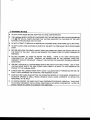
Regulatory Notices
This equipment is designed to be safe at least under the following conditions:
Indoor use, altitude up to 2000m, temperature 5'C to 40'C, maximum relative
humidity 80% for temperatures up to 31'C decreasing lineady to 50% relative
humidity at4oo/o, mains supply voltage fluctuations not to exceed +!10% of the
nominal voltiage, transient overvoltages according to Installation Category 11 and
Pollution degree 2 in accordance with IEC 6&+.
FGC Notice (U.S. Only)
All models of Lightnin Labmaster series mixers are classified by the FCC as Class A
digitaldevices and as such the following FCC notices apply:
WARNING: Ghanges or modifications to this unit not expressly approved by
the party responsible for compliance could void the user's
authority to operate this equipment.
NOTE: This equipment has been tested and found to comply with the limits for a Class
A digital device, pursuant to Part 15 of the FCC rules. These limits are
designed to provide reasonable protection against harmful interference when
the equipment is operated in a commercial environment. This equipment
generates, uses and can radiate radio frequency energy and, if not instralled and
used in accordance with the manufacture/s instruction manual, may cause
harmful interference to radio communications. Operation of this equipment in
a residential area is likely to cause harmful interference in which case the user
will be required to correct the interference at his own expense.
Shielded cables must be used with this unit to ensure compliance with the Glass
A FCC limits.
lG Notice (Canada Only)
All models of Lightnin Labmaster series mixer are classified by Industry Canada (lC)
ICES-003, lssue 2 as Class A digital devices. Devices that are tested and comply with
Class A FCC Specifications also comply with the Canadian Specification following the
harmonization of Canadian Regulation with existing FCC regulations effective January
31, 1989. As such the following notices apply:
This digital apparatus does not exceed the Glass A limits for radio noise
emissions from digitalapparatus set out in the Radio lnterference Regulations
of the Canadian Department of Communications.
Le present appareil numerique n'emet pas de bruits radioelectriques depassant
les limites applicables aux appareils numeriques de la class A prescrites dans
le Reglement sur le brouillage radioelectrique edicte par le ministere Des
Gommunications du Canada.
CE Notice
Marking by the CE symbol indicates compliance of all models of the LIGHTNIN",t .'
Labmaster series mixers to the Machinery Directive, Low Voltage Directive and
'
Dircc'tive of he European Community.TheLIGHT\{IN LabMastermixerc meettechnical j:
standard EN55022 - Limits and Methods of Measirrements of Radio Interference 'r'' "'
Charac{eristics of Information Technology Equipment (TE) as a Class A device. As such ,
the following notices apply:
EMC
'
WARNING: This is a Class A product. In a domestic environment this product
may cause radio interference in which case the user may be
required to take adequate measures.
VCCI Notice (Japan Onty)
Alf modefs of LIGHTNIN Labmaster series mixers are classified by the Voluntary
Control Councilfor tnterference (VCCI) as Class 1 information technoiogy equipr"ni
(lTE) and as such the following VCCI notices apply:
Glass 1 Notice
:
This equipment complies with the limits for a Glass 1 digital device (devices
used in commercial and/or industrial environments) and conforms to the
standards for information technology equipment (lTE) that are set by the
Voluntary Control Council for Interference for preventing radio frequency
interference in commercial and/or industriat areas.
Consequently, when used in a residential area or in an area adjacent to a
residential area, this equipment may cause radio interference with radio and
television receivers or other communications equipment.
To ensure that such radio interference does not occur, it is important to instatl
and use this equipment in accordance with the manufacturer's instruction
manual.
6.00
1
L-UEIASITE-I
trooo
1.3 MAXIMUM
tro@@
tro@o
trEOE
1.44
(5)
OPTIONAL
STAINLESS
STEEL CHUCK
AVAILABLE AT
EXTRA COST
20.98
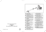
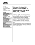
LabMaster IMPELLERS INCLUDED
A100
MODEL
A31 0
DrA. (rN.)
DrA. (rN.)
R100
DrA. (rN.)
L1U1O
4.00
2.72
2.00
3.12
2.00
15U10
MODEL
L1Ul
H.P.
O
1/8
L5U1O
1/8
WATTS
1$
s
A320
C€
DrA. (rN.)
ALL EQUIPMENT DESIGN AND APPLICATION DATA SHOWN HEREIN
AND RELATED KNOW-HOW IS CONFIDENTIAL AND THE PROPERTY
OF THE LIGHTNIN GROUP OF COMPANIES.
NO USE OR DISCLOSURE THEREOF MAY BE MADE WITHOT'T
OUR WRITTEN PERMISSION.
5.00
SPEED
REDUCTION
OUTPUT
R.P.M.
1:1
50 - 1800
3.66:1
20 - 550
IJOHTN'N'
MIXERS AND AERATORS
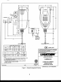
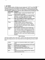
NOTES:
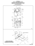
(1) TOTAL MIXER WEIGHT: 18 LBS. OPTIONAL RING STAND WEIGHT:14 LBS.
(21 POWER CORD W|TH GRoUNDED PLUG. LENGTH APPROX. 6 FEET
(3) ALL DTMENSTONS ARE rN TNCHES.
(4) THE SHAFT LENGTH OF THE 11U10 MODEL CAN BE ADJUSTED BY
PASSING THE SHAFT THROUGH THE UNIT.
(5)
MODEL 15U10 ONLY
CERTIFIED BY:
coMPLrANr
DIMENSION DRAWING
LabMaster
@
L{U{O & LsU{O
CERTIFIED
VARIABLE SPEED
@ ueHrNrx
LABORATORY MIXER
2001
DRAWTNG
Figure
- General Arrangement Drawing
NO. DS-P-I 340(BOOK)
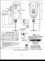
600-
5.00
LIEHTNIN
tltlf-]
t-IaEuasrE!--l
@o@o
1.3 MAXIMUM
Eo@o
trooo
trEOE
2.00
-,L
4.50
2.60
3.03
1.44
(6)
OPTIONAL
STAINLESS
STEEL CHUCK
AVAILABLE AT
EXTRA COST
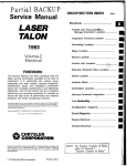
20.98
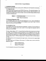
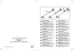
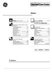
RS.232 PORT PERMITS
FEEDING DATA TO
LAB COMPUTER
-7.25
LabMaster IMPELLERS INCLUDED
MODEL
A31 0
4100
DrA. (rN.)
DrA. (rN.)
R100
DrA. (rN.)
4.00
2,72
2.00
3.12
2.00
L1U1OF
LsU1OF
SPEED
MODEL
H.P.
WATTS
L1U1OF
1/8
90
1:1
LsU1OF
1/8
90
3.66:1
REDUCTION
RJ JACK
A320
DrA. (rN.)
( € coMPunr-rr
5.00
ALL EQUIPMENT DESIGN AND APPLICATION DATA SHOWN HEREIN
AND REI-ATED KNOW-HOW IS CONFIDENTIAL AND THE PROPERW
OF THE LIGHTNIN GROUP OF COMPANIES.
NO USE OR DISCLOSURE THEREOF MAY BE MADE WITHOUT
OUR WRITTEN PERMISSION.
OUTPUT
R.P"M.
50.
1800
20 - 550
TEMPERATURE PROBE
READOUT IN " F OR C
RANGE: 50 . 1800 RPM
TOTAL MIXER WEIGHT: 18 LBS. OPTIONAL RING STAND WEIGHT: 14
(1) VARIABLE SPEED
(2)
DIMENSION DRAWING
L
BS.
LabMaster
(3) POWER CORD W|TH GROUNDED PLUG. LENGTH AppRoX. 6 FEET
(4) ALL
DTMENSTONS ARE tN |NCHES.
(5) THE SHAFT LENGTH OF THE LlU10F MODEL CAN BE ADJUSTED By
L{ U{ OF & LsU{
PASSING THE SHAFT THROUGH THE UNIT.
(6)
liIGIJilIIIN"
MIXERS AND AERATORS
NOTES:
MODEL LsU10F ONLY
CERTIFIED BY:
CERTIFIED
DATE:
Figure 2 - General Arrangement Drawing
OF
VARIABLE SPEED LAB TIIXER
WITH COMPUTER COHTROLLER
DRAWTNG
NO. DS-P-13sC(BOOK)
LIGHTNIN LabMaster Mixer Installation and Operation
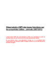
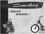
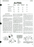
2.1. Mount tre mixer on fte UGIITNIN ring smd (u ank rim). Ins€rt the mixer shaft inio tbe shaft
chuck and tighren If shaft run-out is excessive, rechuck ttre shaft. Orieirt the shaftfiryello in
the approximate location illustzfd in ttre plan and elerration views.
Pivot
Point
P-osition I
Mixer
Shaft
to the Right
ofTanlr
i
l\
lmpeller
Rotation
-
aJ
l-.-
t
l.r
ry6.8
\
OPTIMUM MOUNTING
ANGUI-AR OFF CENTER
-.1
ON CENTER MOUNTING
Airning the shaft off center as shown
avoids vortexing and the need for tank
baffles. This position achieves strong
top-to-bottom turnover. Optimal for
most mixing and blending.
Creates vortexing in an unbaffled tank.
l/Vhile undesirable for most work,
vortexing speeds up the dispersing and
dissolving of light liquids and hard-to-wet
powders.
Figure 3 - Initial Installation
2.2.
IabMaster mixer is shi@ configured for the specific destination witr tlre appropriate line
cord Ctreck whether the voltage indicated on the rear of the mixer matches the available mains
voltage.
T}lre
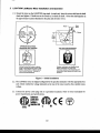
2.3. Connect the power cord's plry only to a grounded receptacle. Refer to mixer nameplate for
power require,rnents and specifications.
Cmfumb
uLsTD3l0f
Hihdb
1I0It2
@cAtucsAt0l0
10
LIGHTNIN LabMaster Mixers are listed to UL Standard 3101, Third Edition, "Laboratory
Equipment'and certified to CAN/CSA 1010
Equipment', IEC 1010, IEC
1010 with Japanese Deviations, FCC Part 15-'Laboratory
Subpart B
Glass A, and EN SS022
Class A and VCCI Level A.
-
2.4. Set fte qpeed md start the mixer, adjrst'mg the
inSection 5 and Section 6.
-
speed to
-
achiwe desired mixer action as ouflined
A cAUTroN
Rotating Parts.
Can cause
minor injury.
Do not
touch
rotating
parts.
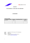
2.5. Formodels provided with additional styles and dianreters of impellers when changes are made:
Install A3l0, ,{315, A320,andAl00 impellers with the convex face ofthe blades facing
?.
b.
c.
up. Tighten
set screw securely.
Install Rl00 impeller wittr the hub body portion of&e inpeller frcing
securely.
ry.
Tight€n set icrew
4200 impeller can be oriented either way on shaft.
4310
4100
Rl00
4315
€
r-t
H
L-J
Figure 4 - Impellers
K
ry
t
2.6. Eaohtime a ditrerent irnpello is installed, the mixer must be reconfigrred to match the style and
diameter of the impellerbeing used- See section 6 for instnrctions.
2.7. rmpeller Adjustnent (DISCONNECT PowER CORD pRIoR To ADTSTING)
LlUl0 and L1U10F models have the ttnu-shaft feature. Remove the blanking grommet
from the top of the housing. Impellers can be {iusted by raising or lowering fire shaft
Loose,n the chuckwith chuckkey, adjust the shaft to zuit depth or desired mixing action.
Retigbten the chuckwittr chuckkey. Re-inshll the grommet if ttnu-shaft featue is not in
a.
b.
use.
On L5U10 and L5U10F series mixers wittrout the thnr shaft feature, adjust the impeller to
the desired position on the shaft and sectlre with set screw.
11
2.8. Do not allow fte mixer horsing to become immemed or zubjected to excessive qplash or qpay.
The gnit should be clemod rs' g a clo& moistened with wrm water only - do not use dgtqgent
or solve,nt basd cleaners. Should it be necessary to clean the LiE{d Crystal Display (I.C-D),
s\ffitch off&e mixer md use lens cleaning tissue which should be lightly mistened with lens
cleaning fluid or warm waEr.
2.9. T\ereare no int€nml user serrriceable components in the mixer. Do not attempt to ope,lr or
dismantle mixers orwarranty will be voided Consult your nearest LIGHTNIN representative
for qualified tecbnical se,lvice assishnce.
2.10.
Two anti-sr.rge fuses prctect the mixer. It is recomme,lrded ftrat the fuses be replaced in
pairs, if necessary. Use only approved fuses. To change the fuses:
Dsconnectpowerto unit
Located fitses above andbelowthe AC power inlet
Using a flat screwdriverblade, insert into tlre slot on the fuse holder, exert a lifile
downward pressure and rotate counter-cloclavise and the firse holderwill reverse out
ofthehousing.
Replace new fuses and re-install holder.
Approved
fuses
z ULICSA
3.15A 250v Anti-surge BUSSMAN type 5506
2.5A 250v Anti-surge BUSSMAN type 5506
IEC
2.11.
REPOSITIONING DURING THE MIXING CYCLE:
Sometimes more than one kind of mixing action is needed- For example, you may first need to
dissolve ligbtpowden, so sbrtwith themixercenteredto seate avortex ftat ryickly disperses
trem into the barch. Stop tlre mixer and disconnect the power cord. Then, to maintain a unifomr
suspension or to blend in other fluids, reposition the mixer to angular off-center.
3
ON/OFF Switch
The Iabtvlaster is activated by deprrssing the ON/OFF button located on
IabNdast€ris ON, the LCD will be illuminated"
4
Keypad Definitions
Rwt
I
2
3
Stop
Reset
Set
4
5
6
7
8
9
Item
0
Enter
Table 1 LabMaster Keypad
T2
trc front of tlre unit When the
5
'
RUN MODE
In RUN mode, the top window will always display the current running qpeed" The DIRECTION icbn
and the IMPELLER STYLE icon will dso indicate fte direction and fre iryella style. The lowetr ri
window will display &e information select€d by the ITEM key. Pressing fte ITEM key will cycle
ftrough the following displays in flre lowerwindow.
VIEW
Power
Torque
Flow
Temperature
Timer
Descriptiorr.
PWRicon, WATTS icon illuminated Outputwatts is
displayed
TORQUE icon, N.CM or OZ.fN icon illuminated- Output
torque is displayed
PUMPING CAP icon, GPM or L/lvIIN icon illuminated.
Flow is displayed
oF
oC
icon illuminated- Extemat @
or
TEMP icon,
is displayed
TIMER icon illuminated Either remaining time on
countdown timer or elapsed run-time diqplayed in MM:SS
form
Table 2 Run Mode Display Options
Views can be 'scanned' by pressing the ENTER key while in RUN mode. Scanning will display each
of trre measured parameters in tum for 10 seconds each. This will continue until the user exits from
ITEM o
lo exit SCAI{ mode )
oTENTER.
scan mode.. To
ITEM
ENTER
RUN
nextVIEW
Enter SCAII mode, exit SCAII mode
Start the motor, if it wurs stopped.
STOP
RESET
SET
Stop motor and illuminate 'STOPPED' icon
Toggles to
Reset any errors, or ignore.
Enter SET Mode
Table 3 Run mode - Keypad definitions
5.1. Faults
The mixer has built in fault tolerance and reporting. Examine *re mixer for the source of the frult and press
RESET or re-start the mixer to eliminate ttre fault condition
If the overload is severe, the motor will stop, O\IER will be
Severe
illuminate{ and an alarm will sourld.
Overload
Shaft Jam
If the shaft is stoppe4
Over
Temperafure
illuminate{ and an alarm will souldIf the intemal temperature exceds the limit, the motor will
sbp, O\IER TEMP will be illuminatd and an alarm will
the motor
sound.
Table 4 Faults
13
will stop, OVER will
be
6
SET MODE
.6;ffi
':'*:
In SET mode the top window will display the current running qperd. The SET icon will
Pressing tlre SET key will cycle through the following options. On entering a set iteiru the crrm#rt
value will be displayed in the lowerwindow or the cune,nt selection will be flashing (direction;:i6qi i
and impeller
ar:row in fire lower windows indicates thatthe user should entir a value.
A
Descriptior
SET ITEM
SPEED icon flashes. C\rrent set qpeed displayed in digits.
Speed
Use 0-9 to enter new set speed.
DIRECTION icon (either cloclcrvise or counter-cloclcvrise)
Direction
illuminated Use ITEM to toggle between directiotts. (Note:
this set item wiil be skipped if the motor is running.)
MM or IN icon flashing. LJse ITEM to toggle between units.
Units
Select MM for SI udts (rnrn, Umrnbrr.cnr,'C) or IN for
oF1.
English units (lq GPM, iuoz. or
TIMER icon flashes. Use 0-9 to enter the value for
Timer
countdown timer in MM:SS form. With the countdown
timer set, the unit will run until the timer expires. When the
timer reaches 00:00, the rurit will stop. If enty is 00:00, the
unit will nm continuously.
IMP icon flashes. Use ITEM for select the impeller type.
Impeller
Upon selecting an impeller, the diameter is set to the default
SUle
value. If you do not wish to use the default diameter, enter
diameter in fuqrav{ for millimetes or BBB.B for inches and
tenths of inches. (Note: If USER is selected the user will be
prornpted by an zurow to enter a flow constant and impeller
diameter).
Table 5 Set Items
After input or selection, there are three options. ENTER accepts setting and retums to RUN mode,
SET accepts setting and cycle to next set itenr, RESET does not change seuing and rehrms to RUN
mode.
ITEM
Toggles to next selection/icon (directioo, units, or impeller
icons)
ENTER
RUN
Accept entered or selected setting and return to RUN mode
STOP
RESET
Stop motor and illuminate 'STOPPED' icon
SET
Start the motor,
if it was stopped.
Ignore inputs for the current set item and return to RUN
mode
Toggle to ttre next set item, accepting any data or selections
made in the previous set item
1,4
Table 6 Set Mode - Keypad Definitions
7
DIAGNOSTIC
.:*,
MODE
Diagnostics are used to test the rurit on start-up ant to calibrate power and terrperature measur€,metrt
7.1.Power On
Test
,
''
;,.,
Every time the mixer is porvered on, the POWER ON test is nrn This checks the hardware. The
LCD windoun briefly diqplay fte model number, softrrare version, line voltage and frcquency. The'
PO\ryER ON test displays emors in the top windo.w. In &e event ofthere being a problerq &e mixer
willreport the following error:
EBAD
I ROM check sumbad
Table 7 Power On Test Error
7.2. Entering Diagnostic mode
To e,lrter diagnostic mode, pow€r m the unit while depressing fte <5> kgy. The unit will display fte
DIA G icon and ARG in ttre top window, and be in diagnostic mode, ready for input To orit the
diagnostic mode, press (9) tfren (ENTER).
T.3.Acceptance Test
The accephnce test tests most of the hardware and peripherals. It t€sa the LCD and controller, the
keyp"4 the micto confroller, and the motor contools. The test begins from diagnostic mode by
pressing
(2) ften (ENTER).
The timer window displays ACCE.
A long and short beep indicates the microprocessors and beeper
working. The local keypad test starts by pressing key I and I is displayed on the LCD. Then,
press the kelpadkeys 2-9 andthe LCD diqplays thatnumber, thenpress key 0 and 10 is displayed"
Then press RUN and diqplay strowsl1, STOP and diqplay showsl2, RESET and display shows 13,
SET and display shows 14, ITEM and display shows 15 and press ENTER to clear and start the
LCD test.
The LCD test stars by ACCE clearing from the upperwindow. All icons and seven segment diglb
are
are displayed.
The beeper sounds once
displayed as follows:
l23-
if all phases of the test pass. If a failure occuni,
krdicates initialisation
frult
Indicates keypad test failure.
Indicates LCD test failure.
To exit the diagnostic mode, press<g> then <Enter>.
15
an error code
will be
,t!,,
7.4. Power Measurement Calibration
To enstne 6e most accuraF resilF, younnrst calibrde fu mixerwift ftis sirryle prcgrm pnorb auy
series of mixing erperimen8
NOTE: Start this procedure with the mixer power on. The shaft and impeller
must be removed and set the mixer to its minimum speed value, press
enter and switch the mixer OFF.
In diagnostic mode, press (6) and then (EI{TER). The mixer runs fte power calibration prcgram.
It staxts ttre mixer and nrns the motor to manimum spee4 incre,menting by 5 % each time. At each
spee4 it calibrates the measure,ment. This pocedure will ake ry to 3%minutes to complete.
The calibration cmbe terminated at any time by pressing
(6) then (ENTER).
(RESEI).
To restart the calibratioq pness
Motor losses axe tsry€rahre d€p€ndexrt It is rccourmended ftraf fte calibration pnogram be nn prior
to any series of mixing erperimenb. Frequent calibration ensures the most accura,te resulf.
NOTE: lf the calibration process fails, the mixer beeps repeatedly until
(RESET) is pressed
The program will exitto RUNmode.
7.5.
Temperature: Galibration Of External Probe
NOTE: This sequence is performed with the mixer motor stopped.
Enter diagnostic mode. In diagnostic mode, press (7) and then (ENTER). Place connected
temperature prob in substance at known temperatrne and compare with temperature reading
displayed on the LCD. To correct the mixer reading, press key I to incrernent reading upwards by
one degree per actuation for degrees C and two degrees per actuation for degrees F. To decrease
the LCD reading, press key 2.
To exit the diagnostic mode, press<9> then <Enter>.
16
8
ACCESSORIES
Power
Output
Torque
Catalog#.
Watts, HP
Thru
Shaft
Temp
Model
RS-232
Probe
RPM
NcM, Oz.in
(115VAC)
Gatalog #
(23oVAC)
L1U1OF
90,117
STD
STD
STD
50-1800
48, 68
836277 PSP
836284PSP
L1U1O
90,
117
STD
N/A
N/A
50-1800
49, 6g
83627'PSP
836282PSP
LsU 1 OF
90,117
N/A
STD
STD
20-550
159
,225
83627&PSP
836285PSP
LsU1O
90,
N/A
N/A
N/A
20-550
159
,225
836276PSP
836283PSP
117
ITIPELLERS
The A310 impeller is standard
on LabMaster mixers. The high
efficiency design develops 50%
more mixing action than ordinary
props. The A310 design also
provides geometric similarity for
accurate scale--up to larger
LIGHTNIN mixers.
The A100 propeller provides
moderate pumping action.
The R500 impeller creates a
cutting, tearing action to disperse
solids and shread fibrous materials.
The A320 impeller is efficient at
blending high viscosity materials.
The A311 Folding lmpeller is
perfect for mixing in vessels with
small, narrow ports. lt opens for
full axial mixing action.
ffi
#
t-l
The A315 impeller is an excellent
choice for gas dispersion with
solids suspension.
The R100 impeller provides high
---,S"
shear and moderate pumping
action.
VY
Heal4y-Duty R ing Stand
m
16 mm (.63') Rod, 610 mm (24.V')high
Heavy Base
316 Stainless Steel Shafts
Model
L1U1O
L5U1
O
Dia.*
Shaft
Length
9.5 mm
610 mm
(.38',)
(24.o',)
9.5 mm
610 mm
(.38")
(24.0',)
a
Bore Dia.
Style
Cat. #829453PSP
Shaft
groenn
II
eller
Ord rl
A3 0
A310
E mm (.31")
A31 0
A100
A100
A100
A100
8 mm (.31")
8 mm (.31')
8 mm (.31')
I mm (.31")
8 mm (.31')
8 mm (.31")
8 mm (.31')
A100
8 mm
(.31')
A100
A100
A200
A315
A315
A315
A320
A320
A320
8
8
8
8
8
8
8
8
8
(.31")
4410'A'
8
R500
R500
R100
R100
Paddle
8
8
8
8
mm
mm
mm
mm
mm
mm
mm
mm
mm
mm
mm
mm
mm
mm
mm
A310
A31 0
Gatalog
Number
143727
143727
*
9.5 mm (.38") dia. shaft turned down to 8 mm (.31") dia. at
impeller end
T7
8 mm (.31')
8
(.31')
(.31')
(.31")
(.31")
(.31")
(.31')
(.31")
(.31')
(.31')
(.31")
(.31'l
(.31")
(.31')
(.31'"1
lnf ormatron
ti
Dia.
64 mm V.5")
(2,5')
Q4 mm
quaro
nno
86-min (3.4')
96 mm (3.8')
114 mm (4.5')
25 mm (1 .O')
38 mm (1.5")
51 mm (2.0')
51 mm e.0'1
'
foldino
51 mrfr (2,0')
nno ouaro
69-min (2.7')
79 mm (3.1")
51 mm (2.0'l
76 mm (3.0')
102 mm (4.0')
127 mm (5.0")
76 mm (3.0")
102 mm (4.0'l
127 mm (5.0'l
100 mm (3.9")
51 mm (2.0')
76 mm (3.0")
38 mm (1 .5')
51 mm (2.0')
51 mm (2.0'l
Catalog
Number
E06955PSP
808999PSP
80941 oPSP
80941 1 PSP
80941 2PSP
800570PSP
800569PSP
800568PSP
800578PSP
800580PSP
80941 TPSP
80941 SPSP
829448PSP
869468PSP
869470PSP
869472PSP
86951 3PSP
86951 5PSP
869381 PSP
218837 PSP
869579PSP
869580PSP
80941 4PSP
80941 sPSP
800579PSP
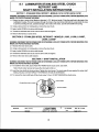
8.1 LABMASTER
STAINLESS STEEL CHUCK
RETROFITAND $.';I:-
SHAFT TNSTALLATTON TNSTRUCTIONS
I
sEcTroN - STATNLESS STEEL RETROFTT - MODEL9 LlU10, L:t910J,,f#!rJ9,,L1.t119F"*, ,, .
'WARtllNG:DISICO}.INECTMOTORPOTITERCORDOROTIIERII,ISE
LOCKOUTPOVTERSUPPLYBEFORESETI/ENGTHIS!
MD(ER FYE PROTECNON MUST BE I'i'OTIN.
1.1 Placeahexkeyorscrewdriver(Maximumdiameter0.lT5",Minimumlength4")intothesmallholeinlhebackofthe
LabMaster housing. The tool must pass through the holes in the mixer drive shaft and intg a cup inside the case
to prevent; bending the tool, possible damage to the inside of the mixer, and the drive shaft ftom tuming.
1.2 Using a strap wrench or locking pliers, remove the steel
chuck.
'i
1.3 Apply Loctite 222M5 to the drive shafi threads
1.4 Thread the stainless steel chuck onto the drive shaft and tighten.
1.5 Remove the hex key or screw driver.
SECTION 2 . STAINLESS STEEL RETROFIT - MODELS L1UO3, L1UO8, L1UO8F,
L5U08, LsUO8F
WARNll,lG: DISCOI,INECTMOTORFOUITERCORDOROTIIERVU|SE
MD(ER FYE PROTECTION MUST BE WOFIN.
LOCKOUTPCIVERSUPFLYBEFORESERVICINGTTIIS
2.1 Restrain the mixer drive shaft.
2.2 Using a strap wrench or locking pliers, remove the steel chuck.
2.3 Apply Loctite 222MS to the drive shaft threads.
2.4 Thread the stainless steel chuck onto the drive shaft and tighten.
2.5 Remove the mixer drive shaft restraint.
SECTION 3 . SHAFT INSTALLATION
WAR}.IING: DFiCO].INECTMOTORPOI/UERCORDOROTHERI,VISE
MXER EYE PROTECTION MUSTBEWORN.
LOCKOUTFOVT,ERSTJPPLYBEFORESERMCINGT}IIS
3.1 To install the mixer shaft, back off (DO NOT REMOVE) the chuck screw, see below.
Note: Chuck screw removalwill cause the chuck grip to fall out.
3.2 Insert the mixer shaft into the chuck bore. Tighten the chuck screw. The chuck grip will press against the mixer shaft
holding it in place. DO NOT IMPACTTHE WRENCH OR USE AN EXTENSION
3.3 To remove the mixer shaft back off the chuck screw
1/4 turn. DO NOT REMOVE the chuck screw.
CHUCK GRIP
STAINLESS STEEL CHUCK
CHUCK SCREW
DATE 11-6-02
REVISED
LIGHTNIN
TUIIXERS
AND AERATORS
1E
@
uc,urMru lNsr. No. lr-s239
2oo2
PAGE
I oF I
9
LabMaster FEATURES
I RS-232 port permits recording data and remote qomputer operation.
I Speed Display: 5f1800 rpm for direc{ drive; 2f550 for gear drive
I Process Watts bnd Torque Display
r
Timer Display (counts up or down)
I
t
I
I
I
I
Overload indicator and alarm
r
Chemically Resistant Housing
t
I
I
I
I
Flow rcadout (Umin or GPM) for sevep different impellers
Standard Temperature Probe -Readouts in
oF
or
oC.
i
Thru-Shaft Design for infinitely variable impeller position.
Calibration for process watts and temperature measurement.
User-defined acceleration/deceleration rates with optional software package (default set by factory).
Universal Mounting Clamp (use with ring strand or tank
rim).
:
i:
Tactile and audible feedback, sealed membrane control panel
Fuse protection for severe overload
Minor overload protection via automatic speed level contpl
90 Watts (117 hp),115 or 230 volts, 50/60 Hz
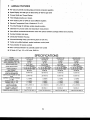
SPECIFICATIONS
f
MODEL
f NPUT VOLTAGE +/- 15o/o
]NPUT CURRENT AMPS AC
NPUT FREQUENCY Hz +l-5Yo
SPEED RANGE RPM
SPEED REGULATION
TIMER ACCURACY
MAX TORQUE
POWER PEAK AT MAX
RPM FOR 30 MINUTES
CONTINUOUS POWER AT MAX
RPM
CURRENT AT RATED TORQUE
+t- 15%
CURRENT LIMIT +l- 15%
CURRENT TRIP +I- 15%
FUSES5X20mm
FAST ACTING 25OV
INTERNAL TEMP TRIP
POf NT +l- 5% DEG. C
DERATING ABOVE 25 DEG. C
11U10(F) 1 15V
1 15 VOLTS
2 AMPS
11U10(F) 230V
234 VOLTS
2 AMPS
15U10(F) 115V
115 VOLTS
2 AMPS
Lsu10(F) 230V
230 VOLTS
2 AMPS
50/60
50/60
50/60
50/60
50 TO 1 800
+I- 5 RPM PLUS ftI
+/- 0 .5o/o OF SET SPEED
+l- 2o/o OF SET TIME
68 |N-OZ
50 TO 1800
+I- 5 RPM PLUS KI
+/. O .5% OF SET SPEED
+l'2o/o OF SET TIME
68 !N-OZ
20 TO 550
+I- 5 RPM P-LUS ftT
+/- O .5% OF SET SPEED
+l- 2o/o OF SET TIME
225 IN-OZ
20 TO 550
+/- 5 RPM PIUS /+l
+/- O .5% OF SET SPEED
+l- 2a/o OF SET TIME
225 IN-OZ
60 WATTS
60 WATTS
75 WATTS
75 WATTS
25 WATTS
25 WATTS
40 WATTS
40 WATTS
1.2 AMPS
1.2 AMPS
1.2 AMPS
1.2 AMPS
1.4 AMPS
1.7 AMPS
1.4 AMPS
1.7 AMPS
1.4 AMPS
1.7 AMPS
1.4 AMPS
1.7 AMPS
3.15 A 250T3.15
2.s A 25AT2.5
3.15 A 250T3.15
2.5 A 250T2.5
60 DEG. C
60 DEG. C
1. 5 WATTS PER DEG. C
1. 5 WATTS PER DEG. C
19
58 DEG.
c
1. 5 WATTS PER DEG. C
58 DEG. C
1. 5 WATTS PER DEG.
c
10 SALES OFFICES
LIGHTNIN LabMaster
.il'
,'
PRECISION MDilNG INSTRUMENTS
lu
.., ; tft
j
In addition to our hblvlastsr solid-state, microprocessor-coiiuolled mtxers, LIGHTNIN offers a complete
line of fluid mixers for the laboratory and process industies.
LIGHTNIN
can make lab work easier and more precise. Just call us.
Telluswhatyourlab
neods to stir
ormi4 andwell have yourunit
delivered.
"
=.t.t't'"
'
In fact, call anytime you have a question about mixing. Youll get answers drawn from over 50,V"gt of
mixing erperience for rylications lutge aod small LIGHTNIN mixers are at work around the clock itoing
hundreds of thorsands of specific jobs for labs and production processes arotmd the world.
For immediate details
on LIGHTNINmixers
or a demonstation,
dt
LIGHTNIN
Toll-free in the US 1-888 MIX BEST (l-888-649-2378)
United Kingdom
Brbworth +44 (0) 1604-88-075
USA
Rochester, NY +1 (585) 436-5550
Australia
Homebush Bay +61 (2) 9763-4901
China
+86 (21) 5495-5616
Shanghai
Singapore
Jrnong +65 -6264-4366
20
1
or the
LIGHTNIN
11 WARRANTY
X1ne //lcltTMlNmherwurmty In fte case of a frihre of my mixer srryplisd, which is tre result of defective
material on wor*rnanship, we will rryir or replace it to your satisfrctio4 or refund the purchage pioe.- T
warranty €td€nds to twelve (12) months after first installation offte mixer or for eigbteen.(18)po'ffu
ib shipment fiom our frctory, whichwerperiod is shorter.
4!g,:
REPLACEMENT PARTS, INSTRUCTION MANUALs, euclnol.iIi AND
MIXING APPLICATION TECHNICAL SUPPORT
sPX PROCESS EQr.IPMENT
LIGHTNIN
P.O. Box 31370
Rochester, New York 14603
Tel. (s85) 436-sss0
Fax (5S5) 43.q-51p9, .
LIGHTNIN
'
.. ' ,
sales engineens are located in prinrcipal cities arcund the world.
2I
*'
LIGH
FOR AN UP TO DATE REPRESENTATIVE LIST
PLEASE GO TO: www.lightnin-mixers.com
-oR-
CALL: 1-888-649-2378
1-888-MlX-BEST
REVISION
P
DATE 1428t05
REVISED 01/05/06
LIGHTNIAP
MIXERS AND AERATORS
INST. NO. lT-3839
'usnrntn
zms
PAGE 1 OF
1