1
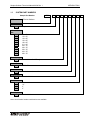
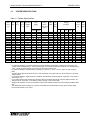
Operation and Maintenance Manual for KFZSS KF Series Simplex Softener Systems Catalog # _______________________ Serial # ________________________ USFilter 10 Technology Drive Lowell, Massachusetts 01851 Tel: (800) 875-7873 • Fax: (978) 441-6025 Email: [email protected] 68/KFZSS-030 – 06/04 Rev. 1 CAUTIONS AND WARNINGS Prior to operating or servicing this device, this manual must be read and understood. If something is not clear, call for assistance before proceeding. Keep this and other associated manuals for future reference and for new operators or qualified service personnel. All electrical work should be performed by a qualified electrician in accordance with the latest edition of the National Electrical Code, as well as local codes and regulations. To avoid electrical shock hazard, do not remove covers or panels when power is supplied to the device. Do not operate the device when covers or panels are removed. WARNING A faulty pump motor or wiring can be a serious shock hazard if it or surrounding water is accessible to human contact. To avoid this danger, DO NOT remove any grounding wire from the system. DISCLAIMER STATEMENT This operation and maintenance manual is intended to be used with the component manufacturer literature provided in the Appendix. These manuals should provide complete and accurate information to meet your operating and/or service requirements based on the information available at the time of publication. However, USFilter assumes no responsibility for the technical content of the manufacturer literature. This manual should be read fully and understood before installation, operation or maintenance of the system is attempted. The information in this manual may not cover all operating details or variations or provide for all conditions in connection with installation, operation and maintenance. Should questions arise which are not answered specifically in this manual, contact the USFilter Technical Support Department at the phone number provided on the cover of this manual. USFilter reserves the right to make engineering refinements that may not be reflected in these manuals. The material in these manuals is for informational purposes and is subject to change without notice and should not be construed as a commitment by USFilter. USFilter assumes no responsibility for any errors that may appear in this document. This manual is believed to be complete and accurate at the time of publication. In no event shall USFilter be liable for incidental or consequential damages in connection with or arising from the use of this manual. Copyright 2004 USFilter Printed in the United States of America. All rights reserved. THIS BOOK OR PARTS THEREOF MAY NOT BE REPRODUCED IN ANY FORM WITHOUT THE WRITTEN PERMISSION OF THE PUBLISHERS. PROPRIETARY RIGHTS STATEMENT This manual discloses information in which USFilter has proprietary rights. Neither receipt nor possession of this manual confers or transfers any right to the client, and by its retention hereof, the client acknowledges that it will not reproduce or cause to be reproduced, in whole or in part, any such information except by written permission from USFilter. The client shall have the right to use and disclose to its employees the information contained herein for the purpose of operating and maintaining the USFilter equipment, and for no other purpose. In the event the content of this manual is altered or section/items are omitted during a reproduction, in whole or in part, and instructions or definitions within the reproduction result in personal injury to those who follow the altered instructions, the burden of responsibility for personal injury falls solely on the party who affects the reproduction. MANUAL USER’S GUIDE This manual describes the procedures necessary to install, operate, and maintain your USFilter Duplex Softener system. Please read this manual carefully before installing and operating your equipment. The equipment warranty may be voided if installation or operation instructions are not followed correctly. Warnings, Cautions, and Notes are used to attract attention to essential or critical information. Warnings and Cautions will appear before the text associated with them, and notes can appear either before or after associated text. WARNING Warnings indicate condition, practices, or procedures which must be observed to avoid personal injury or fatalities. CAUTION Cautions indicate a situation that may cause damage or destruction of equipment or may pose a long term health hazard. NOTE: Notes are used to add information, state exceptions, and point out areas that may be of greater interest or importance. EQUIPMENT SUPPORT USFilter continually strives to provide safe, efficient, trouble-free equipment using the optimum technology for your application. If problems should develop, USFilter’s worldwide network of technical support will be available to provide assistance. For service, sales, parts, or additional manual copies call your area representative or USFilter, Technical Support Department at the number provided on the cover of this manual. TABLE OF CONTENTS SECTION DESCRIPTION 1.0 INTRODUCTION PAGE 1.1 System Function .................................................................................... 1-1 1.2 Quality Assurance/Quality Control......................................................... 1-1 1.3 System Part Numbers............................................................................ 1-2 1.4 System Specifications............................................................................ 1-3 2.0 SYSTEM INSTALLATION 2.1 Equipment Included ............................................................................... 2-1 2.2 Precautions Before Installation .............................................................. 2-3 2.3 Installation of Media............................................................................... 2-3 2.4 Valve and Piping Installation ................................................................. 2-5 3.0 OPERATING INSTRUCTIONS 3.1 Regeneration Setup............................................................................... 3-1 3.2 System Operations ................................................................................ 3-2 3.3 Troubleshooting ..................................................................................... 3-2 4.0 SHUTDOWN AND STORAGE 4.1 5.0 Shutdown and Storage Procedure......................................................... 4-1 SAMPLING AND TESTING 5.1 General Sampling and Testing Guidelines ............................................ 5-1 5.2 Sampling and Testing ............................................................................ 5-1 5.3 Resin Sampling Procedure .................................................................... 5-2 TABLE OF CONTENTS SECTION DESCRIPTION 6.0 MAINTENANCE 6.1 7.0 PAGE General Maintenance Guidelines .......................................................... 6-1 APPENDIX 7.1 Glossary of Terms ................................................................................. 7-1 7.2 Replacement / Spare Parts List ............................................................. 7-3 7.3 QA Inspection Report ............................................................................ 7-4 7.4 Component Manufacturer Literature...................................................... 7-4 For Product and Service Information USFilter 10 Technology Drive Lowell, MA 01851 Telephone: FAX: (978) 934-9349 (978) 441-6025 For Technical Support Telephone: Email: (800) 875-7873 Extension 5000 [email protected] Simplex Softener Timeclock Manual 06/04 Rev. 1 1.0 INTRODUCTION INTRODUCTION Congratulations on your selection of your water purification system. This system is designed and manufactured to the highest standard of quality and fully inspected prior to shipment. In order to get maximum performance, we ask you to read all of the following instructions before installing and operating this system. Any warranty offered will be void unless directions are followed exactly. This manual is divided into sections for easy reference. Review this manual thoroughly and then return to section 2.0 System Installation for step-by-step installation instructions. If you need technical assistance in operating or maintaining your unit, call your local representative. If you require further assistance call the Technical Support Department at the phone number provided on the cover of this manual. 1.1 SYSTEM FUNCTION The function of your water softener is to reduce the hardness in feedwater using ion exchange resin. The water softener vessel contains high quality cation resin in the sodium form that removes hardness. Hardness will create scale on reverse osmosis membranes, water heaters, boilers, and other equipment if not removed. Calcium, magnesium, and other cations removed by the resin are replaced with sodium ions. The resin has a fixed capacity based on the pounds of salt used per cubic foot of resin during regeneration. Flow rate, TDS, and other factors will dictate the actual capacity of the resin. When the capacity is exceeded, the resin will allow the hardness ions to pass through the unit. Before the capacity is exceeded, the unit is removed from service and regenerated with a solution of sodium chloride (brine). Completion of the regeneration steps allows the water softener to be returned to the service mode. 1.2 QUALITY ASSURANCE/QUALITY CONTROL We have defined Quality Assurance and Quality Control into a series of engineering and manufacturing practices and control procedures to insure that you receive the finest product available in the world. We will continue to update these practices and procedures on an ongoing basis in an effort to improve our systems and to insure that they continue to reflect state-of-the-art technology and reliability. Quality assurance is the cornerstone of our quality program. It begins with the selection and qualification of components and materials. Before suppliers are selected, their products must meet or exceed rigid standards set by our Quality Assurance Department. From that point, our incoming material inspection insures only reliable components will be used to manufacture systems. Numerous checks are performed as the system passes through the manufacturing process. Included with the system is a copy of the QA Data Report that includes the check that all components are included. 1-1 Simplex Softener Timeclock Manual 06/04 Rev. 1 1.3 INTRODUCTION SYSTEM PART NUMBERS Sample Part Number KFZS S 009 F X Z F A KF Series Softener KFZS Mode S Simplex Softener Tank Size 009 012 014 016 018 021 024 030 036 042 048 9” x 40” 12” x 52” 14” x 65” 16” x 65” 18” x 65” 21” x 62” 24” x 72” 30” x 72” 36” x 72” 42” x 72” 48” x 72” Vessel Design F Standard Non-Code Fiberglass Control Rating NEMA 3R X Skid Z Stand-alone unit, non-skid Control Type F Timeclock Initiation Pipe Size A B C E 1” 1.5” 2” 3” Resin Options X Standard Volume Note: Not all model number combinations are available. 1-2 X Simplex Softener Timeclock Manual 06/04 Rev. 1 1.4 INTRODUCTION SYSTEM SPECIFICATIONS Table 1-1: System Specifications Pipe Resin Gravel 2Capacity Size Vol. Wght @ 15#/ft3 (ft3) (lbs1/8” dosage (in) x 1/16”) (Kgr) Tank Size DxH (in) 9 x 40 12 x 52 12 x 52 14 x 65 14 x 65 16 x 65 16 x 65 18 x 65 18 x 65 21 x 62 21 x 62 24 x 72 24 x 72 30 x 72 30 x 72 36 x 72 42 x 72 48 x 72 1.0 1.0 1.5 1.0 1.5 1.0 1.5 1.5 2.0 1.5 2.0 1.5 2.0 2.0 3.0 3.0 3.0 3.0 1 2 3 4 5 6 7 1.0 2.0 2.0 3.0 3.0 4.0 4.0 5.0 5.0 7.0 7.0 10.0 10.0 15.0 15.0 20.0 25.0 40.0 none none none 40 40 55 55 75 75 100 100 175 175 250 250 350 500 600 30 60 60 90 90 120 120 150 150 210 210 300 300 450 450 600 750 1,200 Max. Service Flow (gpm) RO Pretreat Stand Alone 3 6 6 9 9 12 12 15 15 21 21 30 30 45 45 60 75 120 19 21 39 22 42 23 46 54 81 52 77 68 91 105 213 250 268 275 3 Fill Backwash/ Inj. Size/ Flow Rapid Color BLFC Rinse (gpm) Flow DLFC (gpm) Cycle Times @ 15#/ft3 dosage (minutes) Brine Tank DxH (in) Max. Salt in Tk (lbs) BW Brine Slow Fast Brine 4,5 5 4 In Rinse Rinse Fill 2.0 3.5 3.5 5.0 5.0 7.0 7.0 9.0 9.0 12.0 12.0 15.0 15.0 25.0 25.0 35.0 50.0 70.0 1/W 2/B 2/B 3/Y 3/Y 3/Y 3/Y 3C/Y 3C/Y 4C/G 4C/G 5C/W 5C/W 6C/R 5/R 6/W 7/B 8/Y 0.5 0.5 0.5 0.5 0.5 0.5 0.5 2.0 2.0 2.0 2.0 2.0 2.0 2.0 5.0 5.0 5.0 5.0 10 10 10 10 10 10 10 10 10 10 10 10 10 10 10 10 10 10 24 26 26 36 24 50 32 24 24 22 22 24 24 32 28 30 22 24 18 18 18 20 22 26 30 32 32 26 26 26 26 34 24 22 20 34 10 12 12 10 10 12 12 12 12 12 12 14 14 12 12 12 10 14 10 18 x 40 20 18 x 40 20 18 x 40 30 24 x 40 30 24 x 40 40 24 x 40 40 24 x 40 12 24 x 54 12 24 x 54 18 24 x 54 18 24 x 54 26 24 x 54 26 24 x 54 38 30 x 48 16 30 x 48 20 39 x 487 26 42 x 607 40 50 x 607 At higher salt dosages, the softener will treat more water between regenerations, create less overall waste, and produce lower-hardness effluent. At lower salt dosages, the softener will use less overall salt. For dosages below 9 #/ft3, consult Technical Support at the number on this manual’s front cover. For other salt dosages, use the formula: Kgr capacity = (#(30 - #) + 16) / 8 x ft3 resin, where # = salt dosage in lbs/ft3 The Brine In and Slow Rinse times are set on each valve timer as a single cycle time, which is the two cycle times added together. For other salt dosages, adjust the Brine In and Brine Tank Fill times using this formula: Cycle time = Time shown x Salt Dosage ÷ 15. For an inlet pressure other than 40 psig, adjust the Brine In and Slow Rinse times using the graphs in Section 8.4 and this formula: Cycle time = Time shown x Flow at 40 psig ÷ Flow at actual psig. At higher salt dosages, use 70% of salt instead; if more salt is loaded, the tank may overflow during the Brine Refill step. The 39x48 brine tank kit includes 3.0 ft3 gravel, the 42x60 brine tank kit includes 3.25 ft3 gravel, and the 50x60 brine tank kit includes 4.5 ft3 gravel.. 1-3 340 340 340 605 605 605 605 861 861 861 861 861 861 1,1746 1,1746 1,9686 2,9726 3,8636 Simplex Softener Timeclock Manual 06/04 Rev. 1 2.0 2.1 SYSTEM INSTALLATION SYSTEM INSTALLATION EQUIPMENT INCLUDED Your system has been shipped to you in the following assemblies. Check to make sure that none of these appear damaged or missing. Each softener assembly consists of each of the following components (per vessel) common to all softeners (see Figure 2-1): 1. (1) Fiberglass vessel with PVC riser tube distributor assembly* 2. (1) Control Valve with cover* 3. (1) Tank-Valve bushing (for 16-24” tanks with 1” valves)* 4. (1) Drain line flow control (DLFC) housing 5. (1) Tube fitting for brine inlet line 6. (1) Kit with assorted DLFC/injector parts 7. (1) Upper Disperser (1.5” valves only) 8. (1) Lot Cation Resin and gravel if necessary* 9. (1) Bushing (3” valves only)* 10. (2) Operating Manuals* 11. (1) Hardness test kit Injector Nozzles DLFC Washers 5 7 Injector Throats 6 4 11 Figure 2-1 Components common to all softeners * = items not shown in photos 2-1 Simplex Softener Timeclock Manual 06/04 Rev. 1 SYSTEM INSTALLATION The brine tank assembly included with all softeners consists of (see Figure 2-2): 12. (1) Brine tank with cover 13. (1) Well with cap 14. (1) Salt Grid (for 24” – 30” tanks) 15. (1) Overflow fitting 16. (1) Safety Valve / Brine Float Valve (for 18” and 24” brine tanks)* 17. (1) Air check assembly (for 24” brine tanks) 18. (1) 3/8” tube elbow, fittings (for 9” – 16” systems)* 19. (1) 0.5” bushing, elbow, fittings (for 18” – 24” systems) 20. (1) length 18’ tubing with tee (for 14” – 24” systems)* 21. (1) Grommet for brine line hole in tank* 22. (1) Lot ¼” x 1/8” gravel (39” – 50” brine tanks)* 19 15 12 13 17 14 Figure 2-2: Brine Tank Components * = items not shown in photos 2-2 Simplex Softener Timeclock Manual 06/04 Rev. 1 2.2 PRECAUTIONS BEFORE INSTALLATION NOTE: Be sure to comply with all local, state, and federal codes. A. WATER PRESSURE: The regeneration valve needs 30 psi minimum pressure to operate effectively. Softeners with 16” x 65” vessels require a minimum of 40 psi. B. WATER TEMPERATURE: Feed temperature should be 45 – 100 °F. C. INLET TURBIDITY: Maximum inlet turbidity is 5 NTU. CAUTION Water pressure is not to exceed 110 PSI, water temperature is not to exceed 100 °F, and the unit cannot be subjected to freezing temperatures. D. ELECTRICAL FACILITIES: An uninterrupted 110V alternating current (AC) electrical supply is required. Make sure the supply is always on, and cannot be turned off with another switch. E. EXISTING PLUMBING: Existing plumbing should be free from lime and iron buildup. If piping is clogged with iron, a separate iron filter unit should be installed ahead of the water softener. LOCATION: The softener should be located close to an open drain. F. G. 2.3 SYSTEM INSTALLATION MANUAL VALVES: Always install manual inlet, outlet, and bypass valves on the system. NOTE: If feedwater or utilities do not meet the above requirements or there is some doubt, contact your local representative or Technical Support at the number provided on the cover of this manual for recommendations. NOTE: Teflon tape is the only sealant to be used on any threaded fittings. INSTALLATION OF MEDIA A. B. Place the softener tanks on a firm foundation as close to the floor drain as possible, and level the vessel. A riser tube distributor assembly has been shipped in each softener vessel (see Figure 2-3. Inspect the slotted basket (bottom distributor) to be sure it is not damaged. Also make sure that the top of the riser pipe is flush with the top of the tank flange when the basket is in the middle of the tank and flat on the bottom. Cover the top of the riser pipe with tape or a plastic cap to prevent gravel and resin from getting inside the riser pipe. 2-3 Simplex Softener Timeclock Manual 06/04 Rev. 1 SYSTEM INSTALLATION Rise r tub e d istrib uto r a sse m b ly Ca tio n Re sin 1/ 8” x 1/ 16” (# 4) Gra ve l (if a p p lic a b le ) Figure 2-3: Softener vessel, riser tube, and media C. Fill the tank about ¼ full with water. Center the riser tube distributor assembly in the top opening of the softener tank. Pour the proper quantity of 1/8” x 1/16” (#4) gravel (see section 1.4) into the softener – make or buy a large funnel to prevent the gravel from spilling. 9” and 12” vessels do not use a gravel underbed. D. Level the gravel as best as possible, making sure that all of the strainer slots are covered. E. Using the same funnel, pour the quantity of cation resin (see section 1.4) into the softener tank. Fill the tank with water and soak the resin for at least 2 hours. 2-4 Simplex Softener Timeclock Manual 06/04 Rev. 1 2.4 SYSTEM INSTALLATION VALVE AND PIPING INSTALLATION Before installing the valve, remove the tape or cap from the top of the riser pipe. CAUTION During installation, refer to Table 1-1 for injector sizes and DLFC sizes. NOTE: Figure 2-4: Injector Components and Assembly A. Verify the correct injector assembly is installed using the following procedure and referring to Figure 2-4 above. Each control valve has been configured for use with a specific diameter tank. If a smaller or larger tank is used instead, a different injector will need to be used: 1. Remove the mounting bolts and lift off the cover and gasket. 2. Compare the installed injector nozzle and throat to the specification table in Section 1.4. If the correct color injector is already installed, skip to step 6. 3. Using a standard screwdriver, unscrew the installed injector nozzle from the injector body. 4. Unscrew the installed injector throat from the injector body. 5. Install the required injector throat and nozzle (see Table 1-1) – these are included in the supplied kit (see Figure 2-1). Screw them into the injector body until snug, but do not overtighten. 6. Reinstall the injector gasket, cover, and bolts. 2-5 Simplex Softener Timeclock Manual 06/04 Rev. 1 B. SYSTEM INSTALLATION (Units with 1”, 1.5”, or 2” valves) Note the required Backwash / Rapid Rinse flow DLFC in Table 1-1. Out of the bag of in line flow control (DLFC) washers, choose the one with this flow stamped on it (flows are in hundredths of a GPM; i.e. 500 = 5 GPM). Install this DLFC flow washer onto the inlet side of the supplied DLFC housing, as shown in Figure 2-5. Make sure the numbers on the washer are facing out. Install with numbers on this side Figure 2-5: 1”, 1.5”, and 2” Valve DLFC Washer Installation C. (Units with 3” valves) Configure the DLFC housing using the following procedures: 1. Loosen and remove the six bolts connecting the two portions of the DLFC housing (shipped loose with the valve). Lift off the upper portion and the flat disc beneath it - containing four cut-outs. In an effort to simplify the drawing, the flat disc is shown with all four cut-outs punched out and only one washer. DLFC washer (typ) Figure 2-6: 3” Valve DLFC Washer Installation 2-6 Simplex Softener Timeclock Manual 06/04 Rev. 1 SYSTEM INSTALLATION 2. Using the washers included in the supplied sizing kit, set up the valve for the DLFC flow listed in Table 1-1. Combine the different washers so they add up to the necessary flow (e.g., 70 GPM would be (2) 25 GPM washers and (1) 20 GPM washer). Each washer is labeled with the flow it is sized for. 3. Make sure the numbers on the washers are facing down, and punch out the same number of holes in the disk as there are washers. 4. Replace the flat disc, making sure to position the holes in the disc directly above the washers. Reinstall the top portion of the DLFC housing, and replace the six bolts. D. Thread the DLFC housing onto the valve’s drain connection. This is the smaller connection on the right side of the 2” valve or on top of the 3” valve, as observed from the front (where the controller is mounted). Make sure that the arrow on the housing is pointing away from the valve. E. Use a silicone base grease to lubricate the two (2) O-rings at the base of each control valve. F. Install the valve’s upper disperser to the bottom of the valve using its instruction sheet (both supplied with the valve). Carefully thread the control valve clockwise into the center opening in the top of the tank. G. Make sure that the riser pipe goes into the center opening in the base of the control valve. Hand tighten only - do not use a wrench or any device to gain leverage or apply additional torque. On the 3” valve, line up the bolt holes on the tank adapter or flange ring with the tapped holes on the softener vessel, and bolt in place. H. Locate the brine tank near the softener. The brine tank location should be such that it will not interfere with access to the softener control valve or filling the brine tank with salt. The brine tank must be placed on a smooth firm foundation. I. For 39” and larger brine tanks only: On the outside of the brine well, pour in the proper quantity of ¼” x 1/8” gravel (see Table 1), and level it. J. Install the piping according to Figure 2-7. 2-7 Simplex Softener Timeclock Manual 06/04 Rev. 1 SYSTEM INSTALLATION Figure 2-7: Simplex Installation K. CAUTION The manufacturer recommends installing a manual bypass line connecting the common inlet and outlet lines so that the softener system can be bypassed if not in use. Solder joints at the drain must be done prior to connecting the drain line to the valve. Failure to do this could cause interior damage to the drain line flow control (DLFC). L. Connect the open port of the DLFC housing to an open floor drain. Do not reduce the pipe or tube size of the drain port connection. Make as short a run of drain piping as possible. If it is necessary to run the drain line overhead, consult technical support for recommendations. M. Loosely thread the supplied tubing fitting onto each valve’s brine inlet connection. N. (3” valves only) Install the supplied bushing to the 1” brine inlet connection. O. Cut the supplied brine tubing into a 6’ piece. Run one piece between the air check assembly on the brine tank to the valve’s brine inlet connection. Refer to figure 28. 2-8 Simplex Softener Timeclock Manual 06/04 Rev. 1 SYSTEM INSTALLATION Figure 2-8: Brine Tubing Connection P. The manufacturer recommends that drain tubing be installed connecting the overflow elbow on the side of the brine tank to an open floor drain. Do not run this line overhead; it must be to a gravity drain. Do not make a direct connection to the floor drain. 2-9 Simplex Softener Timeclock Manual 06/04 Rev. 1 3.0 3.1 OPERATING INSTRUCTIONS OPERATING INSTRUCTIONS REGENERATION SETUP Before placing your softener into Service, use these steps to make sure the regeneration cycle and step times function properly. Refer to the “Timer Setting Procedure” for the Model 3200 Timer in the 2750/2850/2900/3900 Service Manual. When initiating a regeneration or stepping through to the next cycle step, it is very important to wait until all cams and pistons have stopped moving before stepping to the next cycle step. Moving too quickly between steps can cause the timer to get stuck in a particular cycle. NOTE: A. Remove the valve cover by loosening the screws on either side of the valve. B. Initiate a regeneration manually: 1. Rotate the Manual Regeneration Knob slowly clockwise until the valve begins to move to its Backwash position. Let water flow out the drain line until the effluent is clear and clean, typically 20-30 minutes. 2. Rotate the Manual Regeneration Knob slowly clockwise until the valve begins to move to its next position - Brine/Slow Rinse. Check the Brine Tank to see if the level of water is dropping and that water is flowing slowly out the drain line. 3. Rotate the Manual Regeneration Knob slowly clockwise until the valve begins to move to its next position - Rapid Rinse. Check the drain line to ensure water is flowing swiftly. 4. Rotate the Manual Regeneration Knob slowly clockwise until the valve begins to move to its next position - Brine Tank Fill. Leave the valve in this step until the level of water in the brine tank is about 12". 5. Rotate the Manual Regeneration Knob slowly clockwise until the valve begins to move to its next position - Service C. Fill the brine tank with salt to about 6” from the top. Use rock salt or pellets that contain less than 0.6% calcium and magnesium, less than 1.5% sulfate salts, less than 2.0% water-soluble impurities, and no grease, fat, or oil D. Salt replacement is not an automatic step. Operators must check the brine tank periodically to establish a salt refill schedule. Refer to Table 1-1 for the maximum salt allowable in the brine tank. E. The regeneration cycle program is factory set. However, portions of the cycle or program may be lengthened or shortened to suit local conditions. Refer to the “Regeneration Cycle Program Setting Procedure” in the 2750/2850/2900/3900 Service Manual. 1. Calculate the gallons of water the softener can treat between regenerations using this formula: Gals = Resin capacity, gr/ft3 x ft3 resin Water hardness, gr/gal 3-1 Simplex Softener Timeclock Manual 06/04 Rev. 1 OPERATING INSTRUCTIONS The media within the softener that removes the hardness is called the “resin”. The capacity of the resin is shown below for different salt settings. For the DOSAGE and CUBIC FEET of resin, refer to Table 1-1. Table 3-1: Capacities at various salt settings Salt Setting Capacity/Regen 3 15 lb. /ft 30,000 grains / ft3 12 lb. /ft3 28,400 grains / ft3 3 10 lb. /ft 27,000 grains / ft3 3 9 lb. /ft 25,600 grains / ft3 For instance: If Table 1-1 shows a SALT SETTING PER REGEN of 15 lb / ft3, the Capacity per Regeneration (from the table above) will be 30,000 grains / ft3. If Table 1-1 also shows that the vessel contains 5.0 ft3 of resin, and a feed water test reveals a hardness of 17 grains/gallon, the gallons of water that can be treated will be: Gals = 30,000 gr/ft3 x 5 ft3 resin = 8,824 17 gr/gal 2. Calculate the number of days between regenerations using the following formula; round down to the nearest day: Days = Gals from step 1 above estimated usage, gals/day For instance: If you will use an average of 2,000 gallons per day of soft water, the days between regenerations will be: Days = 3.2 8,824 gallons 2,000 gallons per day = 4 days SYSTEM OPERATIONS Refer to the Model 2750/2850/2900/3900 Control Valve Service Manual for descriptions of the valve operations during all cycle steps. These descriptions are located near the beginning of the Control Valve Service Manual, pages 4 and 5. 3.3 TROUBLESHOOTING For general service and performance issues, refer to the Model 2750/2850/2900/3900 Control Valve “Service Instructions” section. 3-2 Simplex Softener Timeclock Manual 06/04 Rev. 1 SHUTDOWN AND STORAGE 4.0 SHUTDOWN AND STORAGE If the system must be shut down and stored, perform the following steps. 4.1 SHUTDOWN AND STORAGE PROCEDURE A. Regenerate the unit B. When the system returns to Service, close all valves in the inlet and outlet piping. C. Disconnect the power to the controller. D. Once each week, open the inlet valve and put the unit into Rapid Rinse for 10 minutes; power must be restored to do this. Once complete, repeat steps B and C. E. When the softener is returned to Service, re-open the inlet and outlet valves, restore power to the controller, and regenerate the unit again 4-1 Simplex Softener Timeclock Manual 06/04 Rev. 1 5.0 SAMPLING AND TESTING SAMPLING AND TESTING This section covers sampling and testing procedures that may apply to your softener. Selected sampling and testing procedures should be performed regularly during the operation of this system. A well kept logbook of test dates and results and of operator observations is an invaluable tool for troubleshooting future performance problems. Any tests used with this system must be performed on a regular basis and must be accurately recorded in a logbook. The frequency of sampling and testing is normally at the discretion of the customer. 5.1 5.2 GENERAL SAMPLING AND TESTING GUIDELINES A. Regular and complete record keeping is critical to maintaining proper operation of a softener. B. Close monitoring of performance will allow operators to detect operating problems early. C. The most important operating data is generated during the initial operation of new equipment. This point forms a baseline that is used to evaluate all future operation. D. Always record a complete set of data immediately before and after performing a regeneration. E. Refer to the remainder of this section for recommended sampling procedures. SAMPLING AND TESTING Hardness is the measurement of calcium and magnesium, which are dissolved minerals that have only limited solubility in water and, therefore, frequently precipitate as scale on piping, water heaters, etc. Your softener contains a material known as resin, which removes these hardness minerals from the water. The amount of hardness in the feed water will determine the number of gallons a water softener can treat between regenerations. If the feed water hardness changes, the length of the service runs must be changed to avoid overrunning the unit or wasting water and salt on excessive regenerations. The amount of hardness in the product water is typically used as an endpoint for service runs. When the amount of hardness in the product rises to a setpoint, the resin is exhausted and must be regenerated with a salt solution (brine). The proper quantity of brine must be present in the storage tank prior to a regeneration. Refer to the Specifications Sheet in Section 1 for the required quantity. Your softener system includes a hardness testing kit. Use this kit and the included instructions to periodically check the hardness of the softener feed and product streams. 5-1 Simplex Softener Timeclock Manual 06/04 Rev. 1 5.3 SAMPLING AND TESTING RESIN SAMPLING PROCEDURE The material inside your softener - called resin - should give you years of soft water, provided your softener is operated within the guidelines given in this manual. Over the years, the resin will gradually lose its capacity to remove hardness and will eventually require replacement. To determine resin capacity, or solve any of the resin-related problems identified while troubleshooting, the resin will have to be sampled and tested using the following procedures. Before starting this procedure, obtain two replacement o-rings to put between each tank and its valve. These are listed in the spare parts section of this manual. NOTE: A. Disconnect the power and interconnecting wiring to the valve timer. B. Open the valve in the bypass line, then close the valves at the softener inlet and outlet. C. Relieve water pressure in the softener by putting the control into regeneration and advancing through each regeneration step (waiting each time for the valve to stop moving) until the control is back in Service (see section 3.3). D. Disconnect the inlet, outlet, drain, and brine piping/tubing at the valve. E. Spin the whole brine valve and timer assembly off of the softener vessel’s top flange. Discard the two O-rings between the valve and the tank. F. To provide the most accurate information on resin condition, a resin sample must be representative of the entire bed. Use a "grain thief" or related device to take a core sample of the resin bed (refer to Figure 5-1). Do not take a sample by taking resin from only the top of the bed. The particulates and resin that normally collect at the top of the bed will not accurately represent the entire bed. NOTE: G. 1. Insert a clean ¼” pipe into the softener vessel and twist it all of the way down to the bottom of the resin bed. 2. Plug the top end of the pipe and slowly lift it out of the vessel. Empty the plug of resin inside the pipe into a clean container. 3. Take enough resin from the bed to fill a one quart jar, and contact your dealer to have the sample tested. Apply silicone lubricant to the top edge of the riser tube distributor assembly and to two new O-rings. Reverse steps 1 - 5 to put the softener back into operation. 5-2 Simplex Softener Timeclock Manual 06/04 Rev. 1 SAMPLING AND TESTING ¼” p ip e (g ra in thie f) Rise r tub e d istrib uto r a ssy Softe ner re sin Figure 5-1: Grain thief for resin sampling 5-3 Simplex Softener Timeclock Manual 06/04 Rev. 1 6.0 6.1 MAINTENANCE MAINTENANCE GENERAL MAINTENANCE GUIDELINES A. MAINTENANCE AND SAFETY Before working on this system, operators must be familiar with the General Safety Precautions at the beginning of this manual. B. VESSELS The vessel for this system is fiberglass and requires no maintenance. If exposed to freezing temperatures, the vessel and its piping must be insulated and heated, or shut down and drained. C. PIPING Operators should check all piping connections periodically for leaks. Any flanges used on the piping may require periodic tightening to prevent leaks. If the system is operated within the temperature and pressure limits, little maintenance is required D. MANUAL VALVES Manual valves should be operated through their full range, at least every 6 months, to assure they function properly and are free of debris. E. PRESSURE REGULATORS Any pressure regulators used in conjunction with this system should be inspected occasionally to assure they are set properly. F. LEAK CHECKING Operators should be alert for leaking pipes, valves, and components. Detecting and repairing a leak while it is still small may prevent lengthy downtime later. 6-1 Simplex Softener Timeclock Manual 06/04 Rev. 1 7.0 7.1 APPENDIX APPENDIX GLOSSARY OF TERMS The terms commonly used in softening and filtration are defined below: BACKWASH: The counter-current flow of water through a resin bed (i.e. in at the bottom of the vessel, out at the top) to clean and reclassify the bed after exhaustion. BED EXPANSION: The effect produced during backwashing: the resin particles become separated and rise in the column. The expansion of the bed due to the increase in space between resin particles may be controlled by regulating backwash flow. BED: The resin contained in a vessel. BRINE: Water saturated with salt. CAPACITY: The ability of the resin to remove hardness, measured in kilograins per cubic foot. CONCENTRATION: The amount of substance in weight, moles, or equivalents contained in a unit volume. CONTAMINANT: Any foreign component present in another substance; e.g., anything in water that is not H20 is a contaminant. CYCLE: A complete sequence of operation. For instance, a complete softener cycle of would involve: Service, Backwash, Brine In / Slow Rinse, Fast Rinse, Brine Tank Refill, and back into Service. EFFLUENT: The solution which emerges from a system unit. EXHAUSTION: The state in which the resin is no longer capable of removing enough hardness from the feed water. FINES: Extremely small particles of ion-exchange resin. FLOW RATE: The volume of solution which passes through a system within a given time. Flow rate is usually expressed in terms of gallons per minute. FREEBOARD: The space provided above the resin bed in an ion-exchange column to allow for expansion of the bed during backwash. GRAINS/GALLON: An expression of concentration of material in solution. One grain per gallon is equivalent to 17.12 parts per million. GRAIN: A unit of weight; 0.0648 grams; 0.000143 pounds. 7-1 Simplex Softener Timeclock Manual 06/04 Rev. 1 APPENDIX HARDNESS: The scale-forming and lather-inhibiting qualities which water, high in calcium and magnesium ions, possesses. INFLUENT: The solution which enters a system unit. ION EXCHANGE: A process by which certain undesired ions of given charge are removed from solution with an absorbent, being replaced in the solution by desirable ions of similar charge from the absorbent. ION: Any particle of less than colloidal size possessing either positive or negative electric charge. KILOGRAIN: A unit of weight; one thousand grains. There are seven kilograins per pound. MEDIA: The material (resin, carbon, quartz) that is used in a fluid-treatment vessel. MINERAL: A natural inorganic substance having a definite chemical composition and structure. RAW WATER: Untreated water from wells or from surface sources. REGENERATION: The process by which a system is conditioned to ready it for another service cycle. RESIN: Typically, a synthetic plastic bead with attached ions that will exchange (trade places with) with other ions in a process feed stream. Used in ionexchange applications. RINSE: The final step in a unit regeneration, in which water is flushed through the unit until the effluent quality is proper. SCALE: The precipitate that forms on surfaces in contact with water. SOFTENING: The removal of hardness - calcium and magnesium - from water. SPECIFIC GRAVITY: The ratio of the mass of a body to the mass of an equal volume of water at 4o C or other specified temperature. TDS: Total Dissolved Solids, in parts per million (ppm. THROUGHPUT VOLUME: The amount of solution passed through an exchange bed before exhaustion of the resin occurs. 7-2 Simplex Softener Timeclock Manual 06/04 Rev. 1 7.2 APPENDIX REPLACEMENT/SPARE PARTS LIST PART NUMBER 05/900005966 05/900005968 05/900005969 05/900005971 05/900005972 18/903001513 18/903001516 18/903001518 B10011249 B10011248 B10011247 B10008143 B10008642 B10008642 B10014348 B10018409 B10018410 B10014271 (2 req’d) B10014272 B10016890 B10016602 DESCRIPTION 1” 2750 Valve head with 1600 injector 1.5” 2850 Valve head with 1600 injector 1.5” 2850 Valve head with 1700 injector 2” 2900 Valve head with 1700 injector 3” 3900 Valve head with 1800 injector Injector Conversion Kit – 1600 injector Injector Conversion Kit – 1700 injector Injector Conversion Kit – 1800 injector O-ring, 2750 Valve Distributor Base (Fleck PN 11710, refer to page 8, item 19 in 2750 Control Valve Manual) O-ring, 2750 Valve Base (Fleck PN 11208, refer to page 8, item 20 in 2750 Control Valve Manual) O-ring, 2750 Valve Top of Tank (Fleck PN 10381, refer to page 8 item 22 in 2750 Control Valve Manual) O-ring, 2850 Valve Top of Tank (Fleck PN 16455, refer to page 6 item 15 in 2850 Control Valve Manual) O-ring, 2850 Valve (Fleck PN 13577, refer to page 6 item 16 in 2850 Control Valve Manual O-ring, 2900 Valve Distributor Base (Fleck PN 13577, refer to page 16, item 36 in 2900 Control Valve Manual) O-ring, 2900 Valve Top of Tank (Fleck PN 13575, refer to page 16, item 37 in 2900 Control Valve Manual) O-ring, 3900 Valve (Fleck PN 16078, refer to page 6, item 11 in 3900 Control Valve Manual) O-ring, 3900 Valve (Fleck PN 16077, refer to page 6, item 13 in 3900 Control Valve Manual) O-ring, 3900 Valve (Fleck PN 16345, refer to page 6, item 24 in 3900 Control Valve Manual) O-ring, 3900 Valve Top of Tank (Fleck PN 16484, refer to page 6, item 31 in 3900 Control Valve Manual) O-ring, 3900 Valve Seal (Fleck PN 15112, refer to page 6, item 14 in 3900 Control Valve Manual) O-ring, 3900 Valve (Fleck PN 16800, refer to page 6, item 23 in 3900 Control Valve Manual) 7-3 Simplex Softener Timeclock Manual 06/04 Rev. 1 7.3 APPENDIX QA INSPECTION REPORT The QA Component Inspection Report will follow the manual. 7.4 COMPONENT MANUFACTURER LITERATURE The vendor literature for your softener will follow this manual. Component Manufacturer 1” Control Valve 1.5” Control Valve 2” Control Valve 3” Control Valve Fleck Fleck Fleck Fleck Manufacturer Model Number 2750 3850 2900 3900 7-4