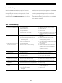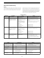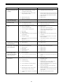
1
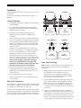
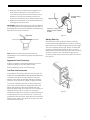
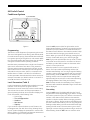
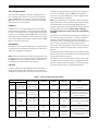
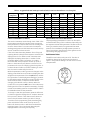
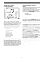
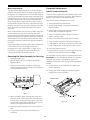
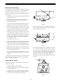
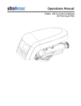
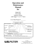
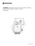
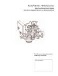
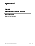
Autotrol®Performa™ ProSoft
With 960 Series Control
5-Cycle Conditioner
5-Cycle FA Filter
Water Conditioning Control System
Installation, Operation and Maintenance Manual
Table of Contents
Installation . . . . . . . . . . . . . . . . . . . . . . . . . . . . . . . . . . . . . 3
Location Selection
Water Line Connection
Drain Line Connection
Regenerant Line
Overflow Line Connection
Placing Conditioner into Operation . . . . . . . . . . . . . . 5
Electrical Connection
960 ProSoft Control . . . . . . . . . . . . . . . . . . . . . . . . . . . . . 6
Programming
Level I Features
Level II Features
Manual Regeneration
Automatic Regeneration
Performa 960 FA Control . . . . . . . . . . . . . . . . . . . . . . .12
Programming
Level I Features
Level II Features
Manual Regeneration
Automatic Regeneration
Removing the Valve Assembly for Servicing . . . . .18
Preventive Maintenance . . . . . . . . . . . . . . . . . . . . . . .18
Injector Screen and Injector
Water Meter
Removing the Control . . . . . . . . . . . . . . . . . . . . . . . . . .13
Specifications . . . . . . . . . . . . . . . . . . . . . . . . . . . . . . . . .21
Pressure Graphs . . . . . . . . . . . . . . . . . . . . . . . . . . . . . . .22
Identification of Control Valving . . . . . . . . . . . . . . . .23
Valve Disc Principle of Operation . . . . . . . . . . . . . . .23
Flow Diagrams . . . . . . . . . . . . . . . . . . . . . . . . . . . . . . . .23
Troubleshooting . . . . . . . . . . . . . . . . . . . . . . . . . . . . . . .28
Disinfection of Water Conditioners. . . . . . . . . . . . . .31
2
Installation
All plumbing and electrical connections must conform to
local codes.
Not in Bypass
Out
In
In Bypass
Out
In
Inspect unit carefully for carrier shortage or shipping
damage.
BY
PA S S
Water
Conditioner
3. Since salt must be added periodically to the
regenerant tank, the location should be easily
accessible.
PA S S
PA S S
PA S S
2. If it is likely that supplementary water treatment
equipment will be required, make certain adequate
additional space is available.
BY
BY
1. The distance between the unit and a drain should be as
short as possible.
BY
Location Selection
Water
Conditioner
Figure 1 - Autotrol Series 1265 Bypass Valve
4. Do not install any unit closer to a water heater than a
total run of 10 feet (3 m) of piping between the outlet
of the conditioner and the inlet to the heater. Water
heaters can sometimes overheat to the extent they
will transmit heat back along the cold pipe into the
unit control valve.
Not in Bypass
Hot water can severely damage the conditioner. A
10-foot (3-m) total pipe run, including bends, elbows,
etc., is a reasonable distance to help prevent this
possibility. A positive way to prevent hot water
flowing from heat source to the conditioner, in the
event of a reverse flow situation, is to install a check
valve in the soft water piping from the conditioner. If a
check valve is installed, make certain the water
heating unit is equipped with a properly rated
temperature and pressure safety relief valve. Also,
be certain that local codes are not violated.
Water
Conditioner
Water
In Bypass
Water
Conditioner
Water
Figure 2 - Typical Globe Valve Bypass System
Drain Line Connection
Note: Standard commercial practices are expressed here.
Local codes may require changes to the following
suggestions.
5. Do not locate unit where it or its connections
(including the drain and overflow lines) will ever be
subjected to room temperatures under 34oF (1 oC) or
over 120oF (49oC).
1. Ideally located, the unit will be above and not more
than 20 feet (6.1 m) from the drain. For such
installations, using an appropriate adapter fitting,
connect 1/2-inch (1.3-cm) plastic tubing to the drain
line connection of the control valve.
6. Do not install unit near acid or acid fumes.
7. The use of resin cleaners in an unvented area is not
recommended.
2. If the backwash flow rate exceeds 5 gpm (22.7 Lpm) or
if the unit is located more than 20 feet (6.1 m) from
drain, use 3/4-inch (1.9-cm) tubing for runs up to 40
feet (12.2 m). Also, purchase appropriate fitting to
connect the 3/4-inch tubing to the 3/4-inch NPT drain
connection.
Water Line Connection
The installation of a bypass valve system is recommended
to provide for occasions when the water conditioner must
be bypassed for hard water or for servicing.
The most common bypass systems are the Autotrol Series
1265 bypass valve (Figure 1) and plumbed-in globe valves
(Figure 2). Though both are similar in function, the Autotrol
Series 1265 bypass offers simplicity and ease of operation.
3. If the unit is located where the drain line must be
elevated, you may elevate the line up to 6 feet (1.8 m)
providing the run does not exceed 15 feet (4.6 m) and
water pressure at conditioner is not less than 40 psi
(2.76 bar). You may elevate an additional 2 feet (61 cm)
for each additional 10 psi (0.69 bar) water pressure.
3
4. Where the drain line is elevated but empties into a
drain below the level of the control valve, form a
7-inch (18-cm) loop at the far end of the line so that
the bottom of the loop is level with the drain line
connection. This will provide an adequate siphon trap.
Overflow Fitting
Installed
Regenerant Tank
5. Where the drain empties into an overhead sewer line,
a sink-type trap must be used.
IMPORTANT: Never insert drain line into a drain, sewer line
or trap. Always allow an air gap between the drain line and
the wastewater to prevent the possibility of sewage being
back-siphoned into the conditioner.
Connect 1/2-inch (1.3-cm)
Tubing or Hose and Run
to Drain
Figure 4
Right Way
Battery Back-Up
The Performa ProSoft conditioner features a battery
back-up feature that will allow the controller to continue to
keep time and record water usage during a power outage.
The control’s display will not light, but the controller will
continue to measure water usage for up to five hours.
When power is restored to the unit, it will continue to work
as before. Connect a nine-volt alkaline battery to the
connecting cable at the back of the conditioner’s control
box, Figure 5.
Figure 3
Note: Standard commercial practices have been
expressed here. Local codes may require changes to these
suggestions.
Regenerant Line Connection
It will be necessary to install the regenerant line to the
regenerant fitting on the valve (3/8-inch NPT).
Be sure all fittings and connections are tight.
Overflow Line Connection
In the absence of a safety overflow and in the event of a
malfunction, the REGENERANT TANK OVERFLOW will direct
“overflow” to the drain instead of spilling on the floor
where it could cause considerable damage. This fitting
should be on the side of the cabinet or regenerant tank.
To connect overflow, locate hole on side of regenerant
tank. Insert overflow fitting (not supplied) into tank and
tighten with plastic thumb nut and gasket as shown
(Figure 4). Attach length of 1/2-inch (1.3-cm) I.D. tubing (not
supplied) to fitting and run to drain. Do not elevate
overflow line higher than 3 inches (7.6 cm) below bottom of
overflow fitting. Do not tie into drain line of control unit.
Overflow line must be a direct, separate line from overflow
fitting to drain, sewer or tub. Allow an air gap as per drain
line instructions (Figure 3).
Figure 5
4
Placing Conditioner into Operation
5. Place the conditioner into operation.
After all previous steps have been completed, the unit is
ready to be placed into operation. Follow these steps
carefully.
A. With the water supply valve completely open,
carefully advance the cycle indicator
COUNTERCLOCKWISE to the center of the REFILL
position. Hold at this position until water starts to
flow through the regenerant line into the
regenerant tank. Do not run for more than one or
two minutes.
B. Advance the cycle indicator
COUNTERCLOCKWISE until it points to the center
of the REGENERANT/SLOW RINSE position.
C. With the conditioner in this position, check to see if
water is being drawn from the regenerant tank.
The water level in the regenerant tank will recede
very slowly. Observe water level for at least three
minutes. If the water level does not recede, or if it
goes up, reference the Troubleshooting section.
D. Advance the cycle indicator
COUNTERCLOCKWISE to the SERVICE position
and run water from a nearby faucet until the water
is clear and soft.
1. Remove control valve cover by first depressing the
plastic clips on the side of the cover. Pull front of cover
up.
Note: The following steps will require turning the
cycle indicator (Figure 6) to various positions.
Manually rotate the camshaft COUNTERCLOCKWISE
only until cycle indicator points to desired position.
(See manual regeneration sections for each control’s
manual operation.)
2. Rotate cycle indicator COUNTERCLOCKWISE until it
points directly to the word BACKWASH.
3. Fill media tank with water.
A. With water supply off, place the bypass valve(s)
into the “service” position.
B. Open water supply valve very slowly to
approximately the 1/4 open position.
IMPORTANT: If opened too rapidly or too far, media may
be lost. In the 1/4 open position, you should hear air
escaping slowly from the drain line.
Electrical Connection
100 VAC, 115 VAC, and 230 VAC units: Remove twist tie
from the power cord and extend cord to its full length.
Make sure power source matches the rating printed on the
control. Be certain a wall switch does not control the
outlet.
C. When all of the air has been purged from the tank
(water begins to flow steadily from the drain), open
the main supply valve all the way.
D. Allow water to run to drain until clear.
E. Turn off water supply and let the unit stand for
about five minutes. This will allow all trapped air to
escape from the tank.
12 VAC: Connect the plug of the transformer (supplied)
secondary cable to the mating socket at the rear or
bottom of the timer housing. Be certain the transformer is
secure and is plugged into a power source of correct
voltage that is not controlled by a wall switch.
4. Add water to regenerant tank (initial fill).
With a bucket or hose, add approximately 4 gallons
(15 liters) of water to regenerant tank. If the tank has
a salt platform above the bottom of the tank, add
water until the level is approximately 1 inch (25 mm)
above the platform.
5
960 ProSoft Control
Conditioner Systems
Cycle Indicator
Regen Button
Press the SET button and the far right number on the
display starts flashing. If you want to change this number,
press the up arrow (↑) button to increase the number or
the down arrow (↓) button to decrease the number. To skip
the number without changing, press the left arrow (←)
button. When you reach the far left digit, pressing the left
arrow (←) button will return you to the far right digit.
Figure 6
Programming
This section covers all aspects of programming the control.
The control is shipped from the factory with default values
for Hardness and Capacity. These default values will result
in a system capacity of 100 gallons (1 cubic meter). While
the control will operate with these values, they should be
changed to meet the actual operating conditions.
Note: If you press and hold either the up arrow (↑) button
or the down arrow (↓) button for more than one second,
the flashing number will increment or decrement at the
rate of 10 counts per second.
Note that some parameters have a single unit of measure
option such as the Rinse Time which is only entered in
minutes. Other parameters have dual units such as Salt
Amount which can be entered in pounds or kilograms. To
select which units are active, look for a comment in the
NOTES column of Table 1 and Table 3. It will reference
another parameter that selects which units are active. For
example, Parameter P12 (Table 3) selects U.S. units if it is
set to “0” and metric if it is set to “1.”
When the number is correct, press the left arrow (←)
button. The first number stops flashing and the next
number starts flashing. You can only change the flashing
number. Continue changing numbers until you reach the
desired setting. Press the SET button. The numbers stop
flashing and the control accepts the new setting. After
approximately 30 seconds, the control starts alternating
the display between Time of Day and Capacity.
Level I Parameters (Table 1)
Note: If a beep sounds, the new setting is not accepted
because it was outside the allowable range. The old value
will be displayed.
Level I Parameters are identified as those that have an LED
indicator on the front panel. The green indicator
illuminates next to the name of the active control setting.
The end user has access to all of these parameters. In
general, pressing the down arrow (↓) button displays the
Level I Parameters in the following order:
•
•
•
•
•
Time of Day
Press the SET button. The display will show the Time of
Day with the minutes digit blinking. If you want to change
this number, press the up arrow (↑) button to increase the
number or the down arrow (↓) button to decrease the
number. To skip the number without changing, press the
left arrow (←) button. The first number stops flashing and
the next number starts flashing. You can only change the
flashing number. When you have reached the far left digit,
pressing the left arrow (←) button returns you to the far
right digit. Continue changing numbers until you reach the
desired setting. Press the SET button to enter the value.
Time of Day
Time of Regeneration
Hardness
Salt Amount
Capacity
If you continue to press the down arrow (↓) button, the
parameters start over with Time of Day. Pressing the up
arrow (↑) button displays the parameters in reverse order.
Refer to Table 1 for a description of these parameters and
the available ranges for each parameter.
6
amount. The default value is 1.0 kilograin (0.1 kilogram). If
this is not acceptable, press the SET button and enter a
new value. Any value between 0.1 and 140 kilograins (.01
and 14.00 kilograms) is allowed.
Time of Regeneration
The next value displayed is the Time of Regeneration. It
has a default value of 2:00 a.m. If this is not acceptable,
press the SET button and change the number. Press the
SET button to enter the value. If 2:00 a.m. is acceptable,
press the down arrow (↓) button.
Note: If the calculation for the system capacity exceeds
9999 gallons (99.99 cubic meters) (P5, Capacity, divided by
P3, Hardness,) the control will display 9999 (99.99) for
capacity until the water usage has dropped the remaining
capacity below that number. When water is flowing
through the system, the colon in the Time of Day display
will blink.
Hardness
Hardness is the next value displayed. This value is the
water hardness expressed in grains per gallon (milligrams
per liter). The default value is 10 grains/gallon (100 mg/L).
If this is not acceptable, press the SET button and enter a
new value. Any value between 3 and 250 grains per gallon
(30 and2500 milligrams per liter) is allowed. Press the SET
button to enter the new value.
At this time, all of the mandatory parameters are filled and
the control is ready for operation. To further increase the
efficiency of the system see P6 and P7 in the Level II
Parameters Section. The display will alternate between the
Time of Day and Capacity if no keys are pressed for
30 seconds. The Capacity value is the volume remaining in
gallons (cubic meters for metric) before a regeneration is
needed.
Salt Amount
Salt Amount is the next value displayed. The default value
for Salt Amount is 6 pounds (2.7 kilograms) of salt; refer to
Table 2 for suggested salt settings.
Verify proper power outage operation by briefly removing
power to the control. The unit will beep and show the time
of day when power is turned on.
Note: This is the total amount of salt for a regeneration, not
pounds per cubic foot. If 6 pounds is not acceptable, press
the SET button and change the numbers. If 6 pounds is
acceptable, press the down arrow (↓) button.
If you wish to fine-tune the operation of this control, refer
to Tables 1 and 3 for details concerning allowable values,
defaults, and parameter descriptions. The programming
procedure is the same for all of these parameters.
Capacity
Capacity is the next value displayed and is expressed in
kilograins (kilograms). Refer to Table 2 for the capacity
setting that corresponds to the resin bed volume and salt
Table 1 - Level I Programming Parameters
Name
Parameter
Description
Range of Values
Minimum
Increments
Default
Units of
Measure
P1
Time of day
AM or PM
1:00 to 12:59
00:00 to 23:59
1
None
Hour:minute
P2
Time of day of
regeneration
1:00 to 12:59
AM or PM
00:00 to 23:59
1
2:00 AM
Hour:minute
P3
Hardness of
water
3 to 250
30 to 2500
1
10
10
100
Grains/gallon
mg/L
P4
Salt amount
0.2 to 51
0.1 to 25.5
0.2
0.1
6
2.5
Pounds
Kilograms
P5
Capacity of unit
0.1 to 140.0
0.01 to 14.00
0.1
0.01
1.0
0.1
Kilograins
Kilograms
7
Notes
Range depends on value
selected for P13. Enter the
current time.
Range depends on value
selected for P13. Skip this
parameter to accept the default
or enter a new time.
Unit of measure depends on
value selected for P12. Test
water hardness and enter that
value.
Unit of measure and default
depends on value selected for
P12. Refer to Table 2.
Unit of measure depends on
value selected for P12. Enter the
unit capacity.
Table 2 - Suggested Salt Dial Settings (Pounds of Salt) For Various Size Softeners - P1 through P5
Capacity Setting
(Kilograins)
12
16
20
24
30
32
35
40
48
60
0.5 Ft3
0.75 Ft3
1.0 Ft3
1.25 Ft3
1.5 Ft3
1.75 Ft3
2.0 Ft3
2.5 Ft3
4.6
9.0
—
—
—
—
—
—
—
—
—
5.6
8.6
14.0
—
—
—
—
—
—
—
—
6.0
8.6
15.0
18.6
—
—
—
—
—
—
—
7.0
11.0
12.6
16.0
23.0
—
—
—
—
—
—
9.0
10.0
12.0
17.0
28.0
—
—
—
—
—
—
9.0
10.0
14.0
21.0
—
—
—
—
—
—
—
9.0
12.0
17.0
30.0
—
—
—
—
—
—
—
—
14.0
21.0
Level II Parameters (Table 3)
Special Notes for Level II Parameters
The Level II Parameters are P6 through P19 in Table 3. The
Home Owner Manual for this product does not mention
these parameters, so the end user does not normally have
access to these values. To access Level II Parameters,
simultaneously press and hold the down arrow (↓) and up
arrow (↑) buttons for three seconds.
The programming parameters in Level II can be used to
increase the efficiency of this conditioner. Especially note
the regenerant Draw Value parameter. This was set at the
factory to meet the needs of a system with low water
pressure. If an installation has higher water pressure or
uses a large injector the efficiency of the system can be
improved by changing P6 and P7.
If the control was alternating between Time of Day and
Capacity when the above button sequence is entered, the
display shows P1. If a different Level I Parameter was
displayed, the display shows the “P” number for that
parameter. Refer to Table 3 to find the “P” number
associated with each parameter. Use the up arrow (↑)
button or the down arrow (↓) button to move from one
parameter to the next. The display cycles through the “P”
numbers shown in Table 1 and Table 3. When you reach
P19, the next P number will go back to P1.
Refill Control Value
The Refill control valve must be set to 33. The valve is
molded into the end of the refill control as shown in
Figure 7. Verify that the setting is 33 and move on to the
next parameter.
When the parameter number you want to change is on the
display, press the left arrow (←) button to display the data
assigned to that parameter. Press the SET button and the
far right number on the display starts flashing. If you want
to change this number, press the up arrow (↑) button or the
down arrow (↓) button. To skip the number without
changing, press the left arrow (←) button. When the
number is correct, press the SET button. The numbers stop
flashing and the control accepts the new setting. If a beep
sounds, the new setting was not accepted. Refer to Table 3
for allowable values for that parameter.
Figure 7 - Refill Control
To change or view other parameters, press the left arrow
(←) button to have the display show “P” numbers. Now use
the up arrow (↑) button or the down arrow (↓) button to
move to the parameter number you wish to change.
To exit the Level II programming mode, simultaneously
press and hold the down arrow (↓) and up arrow (↑)
buttons for three seconds, or wait 30 seconds without
pressing a button. The control starts alternating the
display between Time of Day and Capacity.
8
Table 3 - Level II Programming Parameters
Parameter
Name
Description
Range of Values
Minimum
Increments
Default
Units of
Measure
P6
Refill controller
1 to 99
1
33
1 to 99
1
25
NA
NA
NA
NA
P8
Regenerant
draw value
Not used
P9
Backwash time
3 to 30
1
14
Minutes
P10
Slow rinse time
8 to 125
1
40
Minutes
P11
Fast rinse time
2 to 19
1
4
Minutes
P12
Units of Measure
0 to 1
1
0
P13
Clock mode
0 to 1
1
0
P14
Calendar
override
0 to 30
1
0
P15
Reserve type
0 to 3
1
0
P16
Fixed reserve
capacity or initial
average value
0 to 70
1
30
P17
Operation type
0 to 2
1
2
P18
Salt/capacity
change lockout
0 to 1
1
0
P19
Factory defaults
1
99
P7
9
Days
Percent of
capacity
Notes
Enter the value molded into the
end of the refill controller.
Select number from Table 4 and
enter that number.
NA
Skip this parameter to accept the
default or enter a value.
Skip this parameter to accept the
default or enter a value.
Skip this parameter to accept the
default or enter a value.
0 = U.S., 1 = metric. Skip this
parameter to accept U.S. or enter
1 for metric.
0 = 12-hour clock.
1 = 24-hour clock. Skip this
parameter for a 12-hour clock or
enter 1 for a 24-hour clock.
0 = no calendar override. Skip this
parameter for no calendar
override or enter a value.
0 = variable reserve, 1 = fixed
reserve, 2 = variable reserve with
immediate regen,
3 = fixed reserve with immediate
regen. Skip this parameter to
accept the default or enter a
different reserve type.
Description depends on the value
entered for P15. Skip this
parameter to accept the default or
enter a different value.
2 = 5-cycle
cocurrent conditioner.
0 = none, 1 = salt/capacity change
locked out. Skip this parameter to
accept the default or enter 1 to
lock out salt/capacity change.
Loads in a set of default values.
Refer to the Special Notes for
Level II Parameters section in this
manual. Do Not Change.
• Parameter P18 allows the installer to lock the Salt
Regenerant Draw Value
Amount and Capacity values so they cannot be
changed. When Parameter 18 is set to 1, those two
settings can only be viewed when the control is in the
Level II mode. The settings will be skipped when the
control is in the Level I mode. When Parameter 18 is
set to zero, the Salt Amount and Capacity can be
viewed and changed in either Level I or Level II.
Parameter P7 is used by the control to calculate the
regenerant draw time. The default value of 25 was
selected for a “B” injector with low water pressure or an “A”
injector with moderate water pressure. If this does not
match your installation, press the SET button and enter a
new value. Refer to Table 4 for the correct value. Find the
injector used in the Performa valve. The injector cap is
labeled with the injector letter and the injector is color
coded for easy identification. Next, determine the typical
water pressure for this installation. The Regenerant Draw
Value is an estimate of the flow rate of regenerant through
the injector. This rate varies with water pressure and
injector type as shown in Table 4. The control calculates
the regenerant draw time using this value and the salt
amount. The regenerant draw time is added to the Rinse
Time (P10) to determine the total Regenerant Draw/Slow
Rinse Time.
• Parameter P19 is used at the factory to enter default
values. This parameter does not need to be changed.
Changing this parameter will erase the values for all
other parameters and replace them with default
values.
Manual Regeneration
Electricity is used only to run the timer and to rotate the
camshaft. All other functions are operated by water
pressure. Therefore, in the event of a power outage, all
regeneration positions may be dialed manually. Manual
regeneration can be accomplished by removing the cover
and turning the camshaft COUNTERCLOCKWISE to each
regeneration cycle. Rotating the camshaft
COUNTERCLOCKWISE by hand changes the cycles of
operation. Each cycle position can be identified by viewing
the cycle indicator on the front of the control. The following
cycle times should be used for proper regeneration:
Table 4 - Regenerant Draw Value
Injector
Color
A
B
C
D
White
Blue
Red
Green
Regenerant Regenerant
Regenerant
Draw Value Draw Value
Draw Value
at
at
at 70 psi
50 psi
30 psi
19
26
31
24
30
37
29
37
40
32
48
60
BACKWASH—14 minutes
Regenerant/SLOW RINSE—52 minutes
FAST RINSE/REFILL—10 minutes
PURGE—6 minutes
• This control does not use Parameter P8. No entry is
needed for this parameter.
• Parameter P12 selects the units of measure. Be sure
Do not exceed 10 minutes for the FAST RINSE/REFILL
cycle as this will cause excessive salt usage during the
next regeneration and possibly a salt residue in the
softened water.
that this is set to the correct value before entering any
data for Parameters P3, P4 or P5.
• Parameter P13 selects the clock display mode. If the
12-hour mode is selected, a PM indicator is used. If the
24-hour mode is selected, the PM indicator is not used.
Guest Cycle
To force the control to perform a regeneration, press the
REGEN button (Figure 6). This button is located on the front
of the control. When you press the REGEN button, the
control performs a full regeneration of the conditioner.
• Parameter P15 has four allowable values. Values 0 or
1 will cause the control to wait for Parameter P2, time
of day of regeneration, to begin the regeneration.
Values 2 or 3 will cause the control to start the
regeneration as soon as the capacity is exhausted.
If you press this button again more than one minute
after regeneration begins, but before the regeneration
is complete, a second regeneration will start when the
first regeneration is finished. The display will freeze and
only show the Regen Time Remaining as an indication that
the second regeneration will be performed. When the first
regeneration is complete, the second one will begin and
the display will alternate between Time of Day and Regen
Time Remaining.
• When Parameter P15 selects a variable reserve type,
0 or 2, Parameter P16 is used to calculate the initial
seven average daily water usage values. The control
multiplies the total capacity by the percentage
entered for Parameter P16 and uses that value as the
initial average daily usage for each day of the week
until water usage establishes new averages.
• Parameter 17 has several allowable values, however,
many are reserved for future options and
thus should not be used. Improper regenerations will
occur if P17 is not set to 2.
10
Automatic Regeneration
Since a new installation has no history of water usage, the
control multiplies the percent of capacity value set in
Parameter P16 by the total system capacity to determine
starting average for each day of the week. The factory set
default value for P16 is 30 which means that 30% of the
total system capacity is used for the starting average for
each day.
There are two ways to have the control automatically start
a regeneration: calendar override or having the control
monitor the water usage.
Calendar Override
This feature is set in Parameter P14. It can be set for one to
30 days. If it is set to zero, this feature is disabled. When
this feature is active, the control keeps track of the number
of days since the last regeneration and when that number
equals the value set in P14, a regeneration is automatically
started at the Time of Regeneration set in P2.
Program Parameter P15 is also used to select whether the
control waits until the Time of Regeneration set in
Parameter P2 to start a regeneration, or if the control
should begin a regeneration immediately when the
capacity remaining is less than the reserve.
Control Monitors the Water Usage
The control compares the water usage to the calculated
volume capacity of the system. The control uses the
Capacity Parameter P5 divided by the Hardness
Parameter P3 to calculate the volume capacity of the
system. It also uses a reserve value to determine if a
regeneration is necessary. If the water usage since the last
regeneration is greater than the system capacity minus
the reserve, a regeneration is needed.
Note: If the water usage exceeds 150% of the system
capacity between regenerations, the control will
automatically call for a second regeneration the next day
even if no water is used. This feature is included to make
sure that an exhausted resin bed is completely recharged.
Reserve Options
There are two types of reserve options for this control:
fixed reserve and historical water usage pattern. They are
selected with Parameter P15.
Fixed Reserve
When the fixed reserve is selected, the control multiplies
the maximum system capacity by the percent value set in
Parameter P16 and uses the result as a reserve.
Water Usage Pattern
The other reserve option allows the control to adjust the
reserve based upon the historical water usage pattern of
the system. The control keeps track of the water usage for
each day of the week and uses that day’s average usage
multiplied by 1.2 as the reserve for that day. Every day at
the Time of Regeneration, the control recalculates the
day’s average water usage. If less than 10% of a day’s
average water usage is used, the control will not change
the day’s average. If more than twice the day’s average is
used, the control uses the actual usage in the reserve
calculation.
11
Performa 960 FA Control
5-Cycle Filter System
Performa 960 FA Level I Parameters
(Table 5)
Level I Parameters are identified as those that have an LED
indicator on the front panel. The green indicator
illuminates next to the name of the active control setting.
The end user has access to all of these parameters. In
general, pressing the DOWN ARROW (↓) button displays
the Level I Parameters in the following order:
Performa
FA
TIME OF DAY
TIME OF REGEN
FACTOR A
•
•
•
•
•
FACTOR B
CAPACITY
REGEN TIME
REMAINING
Time of Regeneration
Factor A
Regenerant Dosage
Capacity
If you continue to press the DOWN ARROW (↓) button, the
parameters start over with Time of Day. Pressing the UP
ARROW (↑) button displays the parameters in reverse
order. Refer to Table 5 for a description of these
parameters and the available ranges for each parameter.
Figure 8
This section covers all aspects of programming the
Performa 960 FA control. The control is shipped from the
factory with default values for most parameters. These
default values will result in a system capacity of
100 gallons (1 cubic meter). While the control may operate
with these values, the following parameters must be
changed to meet the actual operating conditions, and
achieve maximum system capacity and efficiency:
•
•
•
•
•
•
•
•
Time of Day
Press the SET button and the far right digit of the display
starts flashing. If you want to change this number, press
the UP ARROW (↑) button to increase the number or the
DOWN ARROW (↓) button to decrease the number. To skip
the number without changing, press the LEFT ARROW (←)
button. When you reach the far left digit, pressing the LEFT
ARROW (←) button will return you to the far right digit.
Time of Day
Time of Regeneration
Note: If you press and hold either the UP ARROW (↑)
button or the DOWN ARROW (↓) button for more than one
second, the flashing number will increment or decrement
at the rate of 10 counts per second.
Factor A
Regenerant Dosage
Capacity of the Unit
Refill Controller Value
When the number is correct, press the LEFT ARROW (←)
button. The far right digit stops flashing and the next digit
to the left starts flashing. You can only change the
flashing number. Continue changing numbers until you
reach the desired setting. Press the SET button. The
numbers stop flashing and the control accepts the new
setting. After approximately 30 seconds, the control starts
alternating the display between Time of Day and
Capacity.
Regenerant Draw Rate
Slow Rinse Time
Note that some parameters have a single unit of measure
option such as the Slow Rinse Time which is only entered
in minutes. Other parameters have dual units such as
Regenerant Dosage which can be entered in gallons or
liters. To select which units are active, look for a comment
in the NOTES column of Table 5 and Table 7 on page 14. It
will reference another parameter that selects which units
are active. For example, parameter P12 (Table 8) selects
U.S. units if it is set to “0” and metric if it is set to “1”.
Note: If the new setting is not accepted because it was
outside the allowable range, the old value will be
displayed.
12
Time of Day
Regenerant Dosage
Press the SET button. The display will show the Time of
Day with the minutes digit blinking. If you want to change
this number, press the UP ARROW (↑) button to increase
the number or the DOWN ARROW (↓) button to decrease
the number. To skip the number without changing, press
the LEFT ARROW (←) button. The first number stops
flashing and the next number starts flashing. You can only
change the flashing number. When you have reached the
far left digit, pressing the LEFT ARROW (←) button returns
you to the far right digit. Continue changing numbers until
you reach the desired setting. Press the SET button again
to save the value.
Regenerant dosage is the next value displayed. Refer to
Table 6 to find the correct regenerant dosage setting
based on the volume of filter media and the average room
temperature of the installation site. Enter the correct value
from Table 6.
Capacity
Capacity is the next value displayed. Refer toTable 7 to
find the correct system capacity setting based on filter
media volume. Enter the capacity setting from Table 7.
Note: The Performa 960 FA control uses the Capacity and
Factor A settings to calculate the system capacity in
gallons (cubic meters). If the calculated system capacity
exceeds 9999 gallons (99.99 cubic meters), the control will
display 9999 (99.99 cubic meters), for capacity until the
water usage has dropped the remaining capacity below
that number. When water is flowing through the system,
the colon in the Time of Day display will blink.
Time of Regeneration
The next value displayed is the Time of Regeneration. It is
similar to Time of Day programming. It has a default value
of 2:00 a.m. If 2:00 a.m. is acceptable, press the DOWN
ARROW (↓) button. If this is not acceptable, press the SET
button and change the numbers. Press the SET button
again to save the value.
At this time, all of the Level I Parameters are programmed.
The display will alternate between the Time of Day and
Capacity if no keys are pressed for 30 seconds. The
Capacity value displayed is the volume remaining in
gallons (cubic meters for metric) before a regeneration is
needed.
Factor A
Factor A is the next value displayed. Factor A is the
potassium permanganate demand of the water being
treated. Determine the potassium permanganate demand
of the water supply and enter that value for Factor A. The
formula below can be used to calculate potassium
permanganate demand from a water analysis.
To complete the initial programming of the Performa 960
FA proceed to the Level II Parameters, page 15.
From water analysis:
Iron content (Fe2) =
________ppm
Manganese content (MN2+) x 2=
________ppm
H2S content x 4=
________ppm
Total Demand=
________ppm
Example:
4.0 ppm iron =
4.0 ppm
3.0 ppm Manganese x 2 =
6.0 ppm
2.5 ppm H2S x 4 =
10.0 ppm
Potassium Perm. Demand =
20.0 ppm
13
Table 5 -Performa 960 FA Level I Programming Parameters
Parameter
Range of Values
Minimum
Increments
Default
Units of Measure
Notes
1
None
Hour: minute
Range depends on value selected
for P13. Enter the current time.
Name
Description
P1
Time of day
AM or PM
1:00 to 12:59
00:00 to 23:59
P2
Time of day of
regeneration
1:00 to 12:59
AM or PM
00:00 to 23:59
1
2:00 AM
Hour: minute
Range depends on value selected
for P13. Skip this parameter to
accept the default or enter a new
time.
P3
Factor A
3 to 250
30 to 2500
1
10
10
100
PPM
PPM x 10
Unit of measure depends on value
selected for P12. Enter potassium
permanganate demand.
P4
Regenerant
Dosage
0.5 to 99.5
01 to 25.5
0.5
0.1
6
2.5
Gallons x 10
Liters x 10
Unit of measure depends on value
selected for P12.
Select regenerant dosage from
Table 6 and enter that value.
Capacity of Unit
0.1 to 140.0
0.01 to 14.00
0.1
0.01
1.0
0.1
PPM-gallons
PPM-liters
Unit of measure depends on value
selected for P12.
Enter the system capacity setting
from Table 7.
P5
Table 6 - Regenerant Dosage Settings (gallons x 10) for Various Size Iron Filters
Temperature
Filter Size/Cubic Feet of Manganese Greensand
0.75 ft3
1.00 ft3
1.25 ft3
1.50 ft3
1.75 ft3
2.00 ft3
2.50 ft3
3.00 ft3
3.50 ft3
50°F
4.0
5.0
6.0
8.0
9.0
10.0
13.0
15.0
18.0
60°F
3.0
4.0
5.0
6.0
7.0
9.0
9.0
11.0
13.0
70°F
3.0
3.0
3.0
4.0
4.0
5.0
6.0
8.0
9.0
Table 7 - Capacity Settings for Various Size Iron Filters
Filter Size
0.75 ft3
1.00 ft3
1.25 ft3
1.50 ft3
1.75 ft3
2.00 ft3
2.50 ft3
3.00 ft3
3.50 ft3
Capacity Setting
7.5
10
12.5
15
17.5
20
25
30
35
14
Table 8 - Performa 960 FA Level II Programming Parameters
Parameter
Range of Values
Minimum
Increments
Default
Units of Measure
Notes
Name
Description
P6
Refill controller
1 to 99
1
33
Must be set to 46 for Performa 960
FA operation
P7
Regenerant draw
value
1 to 99
1
25
Select Regenerant Draw value from
Table 9 and enter that number.
P8
Not used
NA
NA
NA
NA
NA
P9
Backwash time
3 to 30
1
14
Minutes
Skip this parameter to accept the
default or enter a value.
P10
Slow Rinse time
8 to 125
1
40
Minutes
Skip this parameter to accept the
default or enter a value.
P11
Fast Rinse time
2 to 19
1
4
Minutes
Skip this parameter to accept the
default or enter a value.
P12
Units of measure
0 to 1
1
0
0 = U.S., 1 = Metric. Skip this
parameter to accept U.S. or enter 1
for Metric.
0 = 12-hour clock, 1 = 24-hour
clock. Skip this parameter for a 12hour clock or enter 1 for a
24-hour clock.
P13
Clock mode
0 to 1
1
0
P14
Calendar
override
0 to 30
1
0
P15
Reserve type
0 to 3
P16
Fixed reserve
capacity or initial
average value
0 to 70
P17
Operation type
0 to 2
Days
0 = no calendar override. Skip this
parameter for no calendar override
or enter a value.
0
0 = variable reserve, 1 = fixed
reserve, 2 = variable reserve with
immediate regen, 3 = fixed reserve
with immediate regen. Skip this
parameter to accept the default or
enter a different reserve type.
1
30
Description depends on the value
entered for P15. Skip this
Percent of capacity
parameter to accept the default or
enter a different value.
1
2
2 = 5 cycle Cocurrent conditioner
1
P18
Regen. Dosage/
Capacity change
lock out
0 to 1
1
0
0 = none, 1 = Regenerant Dosage/
Capacity change locked out. Skip
this parameter to accept the
default or enter 1 to lock out
Regenerant Dosage/Capacity
change.
P19
Factory defaults
0 to 3
1
99
Loads in factory default values. Do
not change this parameter.
15
Performa 960 FA Level II Parameters
does not match your installation, press the SET button
and enter a new value. Refer to Table 9 for the correct
value. The injector cap is labeled with the injector
letter. The injector is color coded for easy
identification. Next, determine the typical water
pressure for this installation. The Regenerant Draw
value is an estimate of the flow rate of regenerant
through the injector. This rate varies with water
pressure and injector type as shown in Table 9. The
control calculates the regenerant draw time using this
value and the Regenerant Dosage. The regenerant
draw time is added to the Slow Rinse Time (P10) to
determine the total Regenerant Draw/Slow Rinse
Time.
The Level II Parameters are P6 through P19 in Table 8.
The Operating and Maintenance Manual for this product
does not mention these parameters, so the end user does
not normally have access to these values. To access Level
II Parameters, simultaneously press and hold the DOWN
ARROW (↓) and UP ARROW (↑) button for three seconds.
If the control was alternating between Time of Day and
Capacity when the above button sequence is entered, the
display shows P1. If a different Level I Parameter was
displayed, the display snows the “P” number for that
parameter. Refer to Table 8 to find the “P” number
associated with each parameter.
Use the UP ARROW (↑) button or the DOWN ARROW (↓)
button to move from one parameter to the next. The
display cycles through the “P” numbers shown in Table 5
and Table 8 When you reach P19, the display will go back
to P1.
Table 9 - Regenerant Draw Value
When the parameter number you want to change is
displayed, press the LEFT ARROW (←) button to display
the data assigned to that parameter. Press the SET button
and the far right digit on the display starts flashing. If you
want to change this number, press the UP ARROW (↑)
button or the DOWN ARROW (↓) button. To skip the
number without changing, press the left arrow button.
When the number is correct, press the SET button. The
numbers stop flashing and the control accepts the new
setting. If the new setting was not accepted, the display
will show the previous setting. Refer to Table 8 for
allowable values for that parameter.
Injector
Color
A
White
Regenerant Draw Value at:
30 psi
50 psi
70 psi
19
26
31
B
Blue
24
30
37
C
Red
29
37
40
D
Green
32
48
60
• This control does not use parameter P8. No entry is
needed for this parameter.
• Parameter P9 is used to set the backwash time in
minutes. The default in P9 is 14 minutes. If a different
backwash time is desired, press the SET button and
enter a new value.
Slow Rinse Time
To change or view other parameters, press the LEFT
ARROW (←) button to have the display show “P” numbers.
Now use the UP ARROW (↑) button or the DOWN ARROW
(↓) button to move to the parameter number you wish to
change.
• Parameter P10 determines the slow rinse time. The
default value for P10 is 40 minutes. If a different slow
rinse time is desired, press the SET button and enter a
new value.
• Parameter P11 determines the fast rinse time. The
To exit the Level II programming mode, simultaneously
press and hold the DOWN ARROW (↓) and UP ARROW (↑)
buttons for three seconds, or wait 30 seconds without
pressing a button. The control starts alternating the
display between Time of Day and Capacity.
default value is 4 minutes. If a different fast rinse time
is desired, press the SET button and enter a new value.
• Parameter P12 selects the units of measure. Be sure
that this is set to the correct value before entering any
data for parameters P3, P4, or P5.
Refill Controller
• Parameter P13 selects the clock display mode. If the
12 hour mode is selected, a PM indicator is used. If the
24 hour mode is selected, the PM indicator is not used.
• Parameter P6 is used by the Performa 960 FA control
to calculate the refill dwell time and provide accurate
regenerant refill volumes. Refill controller must be set
to 46 for proper system operation. The default value in
P6 is 33. Press the set button and enter 46.
• Parameter P14 is used to set the calendar override
feature. The default value is zero. If set to zero, the
feature is disabled. Refer to Calendar Override, on
page 17 for more information on the calendar
override feature.
Regenerant Draw Value
• Parameter P7 is used by the control to calculate the
• Parameter P15 selects a variable reserve type, 0 to 13.
regenerant draw time. The default value of 25 was
selected for a “B” injector with low water pressure or
an “A” injector with moderate water pressure. If this
For more information see Reserve Options below.
• Parameter P16 is used to calculate the initial average
daily water usage values. The control multiplies the
16
show the Regen Time Remaining as an indication that the
second regeneration will be performed. When the first
regeneration is complete, the second one will begin and
the display will alternate between Time of Day and Regen
Time Remaining.
total capacity by the percentage entered for
Parameter P16 and uses that value as the initial
average daily usage for each day of the week until
water usage establishes new averages. The default is
set for 30% of the capacity. In most installations this is
acceptable.
Automatic Regeneration
• Parameter P17 has been preset to 0. Do not change
this setting. P17 must be set to 2 for Performa 960 FA
operation.
There are two ways to have the control automatically
initiate a regeneration: calendar override or normal
metered water usage.
• Parameter P18 allows the installer to lock the
Regenerant Dosage and Capacity values so they
cannot be changed. When Parameter 18 is set to 1,
those two settings can only be viewed when the
control is in the Level II mode. The settings will be
skipped when the control is in the Level I mode. When
Parameter 18 is set to zero, the Regenerant Dosage
and Capacity can be viewed and changed in either
Level I or Level II.
Calendar Override
This feature is set in parameter P14. It can be set for 1 to
30 days. If it is set to zero, this feature is disabled. When
this feature is active, the control keeps track of the number
of days since the last regeneration and when that number
equals the value set in P14, a regeneration is automatically
started at the Time of Regeneration set in P2.
• Parameter P19 is used at the factory to enter default
Normal Metered Water Usage
values. This parameter does not need to be changed.
Using this parameter will erase the values for all other
parameters and replace them with default values.
Improper regenerations will occur if P19 is set to a 0 or
3. P19 should be set on default number 99.
The control compares the water usage to the calculated
volume capacity of the system.The control uses the
Capacity parameter P5 divided by the Factor A parameter
P3 to calculate the volume capacity of the system. It also
uses a reserve value to determine if a regeneration is
necessary. If the water usage since the last regeneration is
greater than the system capacity minus the reserve, a
regeneration is needed.
Regeneration
When the control begins a regeneration, the display will
alternate between Time of Day and Regen Time
Remaining. The Regen Time Remaining is shown in
minutes. The control will start and stop an internal motor
which drives the cam gear through the various
regeneration positions. The control uses the information
entered in the parameters shown in Table 8 to determine
how long each part of the cycle should last.
Note: If the water usage exceeds 150% of the system
capacity between regenerations, the control will
automatically call for a second regeneration the next day
even if no water is used. This feature is included to make
sure that an exhausted filter bed is completely recharged.
Reserve Options
If power fails during a regeneration cycle, the cycle
completes normally when the power is restored.
There are two types of reserve options for this control:
fixed reserve and historical water usage pattern. They are
selected with parameter P15.
Note: The REGEN button is only active when the display is
alternating between Time of Day and Capacity. When
programming Level I or II parameters, the REGEN button is
not active.
Fixed Reserve
When the fixed reserve is selected, the control multiplies
the maximum system capacity by the percent value set in
parameter P16 and uses the result as a reserve.
The Regen Time Remaining in regeneration will continue to
count down until the cam gear reaches the Service
position.
Manual Regeneration
To initiate a manual regeneration, press the REGEN button.
This button is located on the front of the control. When you
press the REGEN button, the control performs a full
regeneration of the conditioner.
If you press this button again more than one minute after
regeneration begins, but before the regeneration is
complete, a second regeneration will start when the first
regeneration is finished. The display will freeze and only
17
Water Usage Pattern
Preventive Maintenance
The other reserve option allows the control to adjust the
reserve based upon the historical water usage pattern of
the system. The control keeps track of the water usage for
each day of the week and uses that day’s average usage
multiplied by 1.2 as the reserve for that day. Every day at
the Time of Regeneration, the control recalculates the
day’s average water usage. If less than 10% of a day’s
average water usage is used, the control will not change
the day’s average. If more than twice the day’s average is
used, the control uses the actual usage in the reserve
calculation.
Injector Screen and Injector
Inspect and clean regenerant tank and screen filter on end
of regenerant pickup tube once a year or when sediment
appears in the bottom of the regenerant tank.
Clean injector screen and injector once a year:
1. Unplug the wall-mount transformer.
2. Shut off water supply or put bypass valve(s) into
bypass position.
3. Relieve system pressure by opening valve No. 7
(at rear) with a screwdriver (Figure 9).
Since a new installation has no history of water usage, the
control multiplies the percent of capacity value set in
parameter P16 by the total system capacity to determine
starting average for each day of the week. The factory set
default value for P16 is 30 which means that 30% of the
total system capacity is used for the starting average for
each day.
4. Using a screwdriver, remove injector screen and
injector cap (Figure 10).
5. Clean screen using a fine brush. Flush until clean.
6. Using a needle-nose pliers, pull injector straight out.
7. Flush water into the injector screen recess of the valve
body to flush debris out through the injector recess.
Program parameter P15 is also used to select whether the
control waits until the Time of Regeneration set in
parameter P2 to start a regeneration, or if the control
should begin a regeneration immediately when the
capacity remaining is less than the reserve.
8. Clean and flush the injector.
9. Lubricate the O-rings on the injector, injector cap and
injector screen with silicone lubricant only!
10. Reinstall the injector, injector cap and injector screen.
Removing the Valve Assembly for Servicing
IMPORTANT: Do not overtighten the plastic cap. Seat the
cap lightly into position. Overtightening may cause
breakage of the plastic cap that may not be immediately
evident.
1. Unplug the power cord.
2. Shut off water supply or put bypass valve(s) into
bypass position.
3. Remove cover and with screwdriver, relieve tank
pressure by pushing open valve No. 7 (rear flapper) on
control as shown (Figure 9).
11. Plug the wall-mount transformer into outlet; reset
clock if necessary.
12. Slowly open water supply valve or return bypass
valve(s) to the “service” position.
Injector Screen
Turbine
Figure 9
4. When used with a globe valve bypass, loosen and
detach the inlet, outlet, regenerant and drain lines
from the valve. If using the 1265 bypass, loosen and
remove valve from bypass as well as loosening and
removing the regenerant and drain lines.
Injector
Figure 10
5. Unscrew (counterclockwise) and remove valve from
tank.
6. To replace the control valve, reverse the above
procedure.
18
Cap
Water Meter Maintenance
The metering device used with the 960 demand controls
may require simple maintenance. In rare instances, the
turbine wheel of the water meter can collect small
particles of oxidized iron, eventually preventing the wheel
from turning.
Tab
1. Shut off the water supply or put the bypass valve(s) into
the bypass position.
2. Relieve pressure by opening the Backwash Drain
Valve (the seventh back from the control) with a
screwdriver (Figure 9).
3. Loosen and remove the pipe/tube adapters or 1265
bypass from the inlet and outlet of the valve body.
Figure 11
4. Using a needle-nose pliers, remove the turbine from
the outlet housing. Grasp one of the four vanes of the
outer gland and pull straight out to remove turbine
assembly from the outlet of the valve (Figure 10).
4. Relieve system pressure by opening the Backwash
Drain Valve (the seventh valve back from the control)
with a screwdriver, Figure 12.
5. Carefully remove the turbine wheel from the housing.
Use a toothbrush to lightly scrub the iron off the
magnet. Iron buildup on the surfaces can be removed
by soaking the wheel in a mild sodium hydrosulfite
(such as RoVer*) solution for a few minutes. Flush
thoroughly with water.
*RoVer is a trademark of Hach Chemical Company.
6. Carefully reinstall the turbine wheel into the turbine
cage housing. Make sure that the shaft of the wheel
seats into the bearing of the cage. Reassemble the
turbine cage and check that the wheel rotates freely.
Figure 12
7. Reinstall the turbine cage into the outlet of the valve.
5. To remove the camshaft or to reinstall it, the arrow on
the rear of the cam shaft must be pointing at the line
on the rear “hoop” of the top plate. This occurs when
the cycle indicator is rotated to the refill position. Press
down on the back of the camshaft to disengage it
from the rear “hoop” of the top plate, Figure 13.
Slide the camshaft back to disengage it from the timer,
Figure 14.
8. Reinstall the pipe/tube adapters or 1265 bypass to the
inlet and outlet of the valve.
9. Turn on the water supply or put the bypass valve(s)
into the service position and purge the air out of the
system.
To check for proper meter operation, open a downstream
faucet and observe the water flow indication, blinking
colon, on the control display.
Removing the Control
Complete the following steps to remove the 960 ProSoft
control for servicing:
1. Unplug the wall-mount transformer.
2. Shut off the water supply or put the bypass valve(s)
into bypass position.
3. Remove the rear cover by depressing the two tabs
provided on the cover, Figure 11. Lift the front of the
cover and remove to expose the valve body.
Figure 13
19
Figure 14
6. Disconnect the turbine probe from the turbine
assembly.
7. Lift the control off the valve, Figure 15. To replace the
control, reverse the above procedure. Note that the
camshaft needs to be positioned correctly before it
can be inserted into the back of the control. There is a
locating arrow on the camshaft. Position the arrow on
the top of the shaft and slide the camshaft into the
control. Push up on the end of the camshaft, furthest
from the timer, snapping it into place.
Figure 15
20
Specifications
Hydrostatic Test Pressure . . . . . . . . . . . . . . . . . . . . . . . . . . . . . . . . . . . . . . . . . . . . . . . . . . . . . . . . . . . . . . . . . . . . . . . . . . . . 300 psi (20.69 bar)
Working Pressure . . . . . . . . . . . . . . . . . . . . . . . . . . . . . . . . . . . . . . . . . . . . . . . . . . . . . . . . . . . . . . . . . . . . . . . . . . . . 20-125 psi (1.38 - 8.62 bar)
Standard Electrical Rating . . . . . . . . . . . . . . . . . . . . . . . . . . . . . . . . . . . . . . . . . . . . . . . . . . . . . . . . . . . . . . . . . . . . . . . . . . . . . . . . . . . 115V 60 Hz
Optional Electrical Rating . . . . . . . . . . . . . . . . . . . . . . . . . . . . . . . . . . . . 115V 50 Hz, 230V 50 Hz, 200V 60 Hz, 24V 60 Hz, 24V 50 Hz,
100V 60 Hz, 100V 50 Hz, 12V 50 Hz/transformer, 12V 60 Hz/transformer
Electrical Cord (standard rating) . . . . . . . . . . . . . . . . . . . . . . . . . . . . . . . . . . . . . . . . . . . . . . . . . . . . . . . . . .60 inch (1.5 m) 3-wire with plug
Pressure Tank Thread . . . . . . . . . . . . . . . . . . . . . . . . . . . . . . . . . . . . . . . . . . . . . . . . . . . . . . . . . . . . . . . . . . . . . . . . . . . . . . . . .2 1/2 inch-8 male
Riser Pipe Diameter Required. . . . . . . . . . . . . . . . . . . . . . . . . . . . . . . . . . . . . . . . . . . . . . . . . . . . . . . . . . . . . . . . . . . 1.050 inch OD (26.7 mm)
Riser Pipe Length . . . . . . . . . . . . . . . . . . . . . . . . . . . . . . . . . . . . . . . . 1-1/8 ±1/8 inches (31.8 mm) higher than the top of mineral tank
Standard Connection . . . . . . . . . . . . . . . . . . . . . . . . . . . . . . . . . . . . . . . . . . . . . . . . . . . . . . . . . . . .1-inch (25.4-mm) copper tube adapters
Optional Connections . . . . . . . . . . . . . . . . . . . . . . . . . . . . . . . . . . . . 1-1/4-inch, 3/4-inch, 22-mm, and 28-mm copper tube adapters
3/4-inch BSPT, 1-inch BSPT, 1-inch NPT brass pipe adapters
3/4-inch, 1-inch, 25-mm CPVC tube adapters
Regenerant Line Connection . . . . . . . . . . . . . . . . . . . . . . . . . . . . . . . . . . . . . . . . . . . . . . . . . . . . . . . . . . . . . . . . . . . . . . . . . 3/8-inch NPT male
Drain Line Connection . . . . . . . . . . . . . . . . . . . . . . . . . . . . . . . . . . . . . . . . . . . . . . . . . . . . . . . . . . . . . . . . . . . . . . . . . . . . . . . 3/4-inch NPT male
Optional Bypass Valve . . . . . . . . . . . . . . . . . . . . . . . . . . . . . . . . . . . . . . . . . . . . . Rotating handles, full 1-inch porting, reinforced Noryl
Control Module, Tank Adapter . . . . . . . . . . . . . . . . . . . . . . . . . . . . . . . . . . . . . . . . . . . . . . . . . . . . . . . . . . . . . . . . . . . . . . . . . .Reinforced Noryl
Rubber Goods . . . . . . . . . . . . . . . . . . . . . . . . . . . . . . . . . . . . . . . . . . . . . . . . . . . . . . . . . . . . . . . . . . . . . . Compounded for cold water service
Program Clock (Timer) . . . . . . . . . . . . . . . . . . . . . . . . . . . . . 960: Available in English, German, French, Italian, Spanish, Japanese
Regenerant Refill Control. . . . . . . . . . . . . . . . . . . . . . . . . . . . . . .1 to 10 lbs (0.45 to 4.5 kg) of salt or 3 to 19 lbs (1.4 to 8.6 kg) of salt
Injector Size “A” White. . . . . . . . . . . . . . . . . . . . . . . . . . . .Nozzle .042-inch (1.1-mm) diameter, Throat .089-inch (2.3-mm) diameter
Injector Size “B” Blue . . . . . . . . . . . . . . . . . . . . . . . . . . . . .Nozzle .052-inch (1.3-mm) diameter, Throat .099-inch (2.5-mm) diameter
Injector Size “C” Red . . . . . . . . . . . . . . . . . . . . . . . . . . . . .Nozzle .059-inch (1.5-mm) diameter, Throat .099-inch (2.5-mm) diameter
Injector Size “D” Green . . . . . . . . . . . . . . . . . . . . . . . . . . Nozzle .071-inch (1.8-mm) diameter, Throat .147-inch (3..7-mm) diameter
Internal Backwash Controllers. . . . . . . . . . . . . . . . . . . . . . . . . . .7- through 14-inch (17.8- though 35.6-cm) diameter media tanks
All sizes to flow 4.5 gpm/sq ft (183 L/m/m2) of bed area.
For tank sizes above 14 inches in diameter, use an external flow control.
21
Pressure Graphs
Injector #1031363
Injector #1031364
"A" in a 268 Valve
"B" in a 268 Valve
1.00
0.30
0.20
Total
1.25
0.25
0.75
0.20
Rinse
0.05
0.00
0.50
Brine Draw
0.15
0.75
GPM
0.10
M3/hr
Rinse
GPM
M3/hr
0.15
Total
1.00
0.10
0.50
0.05
0.25
0.00
0.00
Brine Draw
0.25
0.00
20
40
400 600
60
PSI
80
100
120
20
800 1000 1200 1400 1600 1800
bar
40
400 600
60
1.25
0.20
0.10
0.05
M3/hr
Rinse
GPM
M3/hr
0.25
Total
0.75
0.10
Brine Draw
0.50
0.05
0.25
0.00
0.15
0.00
0.00
20
40
60
400 600
PSI
80
100
2.25
2.00
1.75
1.50
1.25
1.00
0.75
0.50
0.25
0.00
Total
Rinse
GPM
0.30
1.00
120
"D" in a 268 Valve
1.75
0.15
100
Injector #1030272
"C" in a 268 Valve
1.50
80
800 1000 1200 1400 1600 1800
bar
Injector #1031365
0.20
PSI
Brine Draw
20
120
40
400 600
800 1000 1200 1400 1600 1800
bar
60
PSI
80
7
8
9
10
12
13
14
Flow (GPM*)
1.2
1.6
2.0
2.5
3.9
4.1
4.8
Flow (LPM*)
4.5
6.0
7.6
9.5
14.76
15.5
18.2
22
120
800 1000 1200 1400 1600 1800
bar
Backwash Number
*Approximate flow rates at 60 psi (414 kPa)
100
Valve Disc Principle of Operation
Identification of Control Valving
7 Backwash Drain Valves
5 Refill Valve
3 Inlet Valve
1 Regenerant Valve
6 Rinse Drain Valve
4 Outlet Valve
2 Bypass Valve
Flow Diagrams
1 Service Position
2 Backwash Position
Hard Water
Hard Water
Soft Water
Soft Water
Inlet
Inlet
3
3
2
2
5
5
Outlet
Valve
No.
1 - Closed
2 - Closed
3 - Open
4 - Open
5 - Closed
6 - Closed
7 - Closed
Brine
Adjustment
1
Brine
Adjustment
1
4
Outlet
6
Valve
No.
1 - Closed
2 - Open
3 - Closed
4 - Open
5 - Closed
6 - Closed
7 - Open
Drain
Mineral Tank
4
7
6
23
Backwash
Flow
Control
Drain
Mineral Tank
Brine Tank
7
Brine Tank
4 Purge Position
3 Brining/Slow Rinse Position
Hard Water
Hard Water
Soft Water
Soft Water
Brine
Adjustment
1
Inlet
Inlet
3
2
3
2
5
Outlet
4
5
6
Outlet
7
Drain
Valve
No.
1 - Open
2 - Open
3 - Closed
4 - Closed
5 - Closed
6 - Open
7 - Closed
Brine
Adjustment
1
4
6
7
Drain
Mineral Tank
Valve
No.
1 - Closed
2 - Open
3 - Open
4 - Closed
5 - Closed
6 - Open
7 - Closed
Brine Tank
5 Regenerant Refill Position
Hard Water
Soft Water
Brine
Adjustment
1
Inlet
3
2
5
Outlet
4
6
7
Drain
Valve
No.
1 - Closed
2 - Closed
3 - Open
4 - Open
5 - Open
6 - Closed
7 - Closed
Mineral Tank
Brine Tank
24
Mineral Tank
Brine Tank
Replacement Parts
Performa Valve
15
2
12
3
12
4
14
13
9
8
5
6
1
11
7
10
25
Parts List
Part
Code
Part
Qty.
Code
1
1035807
No.
Valve Assembly, w/o Flow Controls
1
11
2
1035615
960 Standard Camshaft:
1
12
Drain Control Assembly:
1
3
4
No.
1035622
1001606
Description
1
Plumbing Adapter Kits:
1
3/4-inch Copper Tube Adapter Kit
No. 7 (1.2 gpm; 4.5 Lpm)
1001670
1-inch Copper Tube Adapter Kit
1000210
No. 8 (1.6 gpm; 6.1 Lpm)
1041210
1-1/4-inch Copper Tube Adapter Kit
1000211
No. 9 (2.0 gpm; 7.6 Lpm)
1001608
22-mm Copper Tube Adapter Kit
1000212
No. 10 (2.5 gpm; 9.5 Lpm)
1001613
3/4-inch CPVC Tube Adapter Kit
1000213
No. 12 (3.5 gpm; 13.2 Lpm)
1001614
1-inch CPVC Tube Adapter Kit
1000214
No. 13 (4.1 gpm; 15.5 Lpm)
1001615
25-mm CPVC Tube Adapter Kit
1000215
No. 14 (4.8 gpm; 18.2 Lpm)
1001769
3/4-inch NPT Plastic Pipe Adapter Kit
1030502
Ball, Flow Control
1
1001603
1-inch NPT Plastic Pipe Adapter Kit
Injector Assembly:
1
1001604
3/4-inch BSPT Plastic Pipe Adapter Kit
1032970
“A” Injector - White
1001605
1-inch BSPT Plastic Pipe Adapter Kit
1032971
“B” Injector - Blue
1001611
3/4-inch BSPT Brass Pipe Adapter Kit
1032972
“C” Injector - Red
1001610
1-inch NPT Brass Pipe Adapter Kit
1030272
“D” Injector - Green
1001612
1-inch BSPT Brass Pipe Adapter Kit
1000269
Injector Cap Assembly:
1
13
1033444
Turbine Assembly
Regenerant Refill Control
1
14
1001580
Spring, Flapper Valve
15
1030372
7
1000222
.33 gpm
8
1002449
Drain Fitting Elbow (3/4” hose barbed)
9
1000226
Screen/Cap Assembly
1
1041174
Standard
10
1010429
O-Ring
1
1041175
Severe Service
1
*
* Not Shown
26
Qty.
Tank Ring
1000209
5
6
Description
Cover
Valve Disc Kit:
1
1
960 ProSoft Control
1265 Bypass
Performa ProSoft
B Y PA S S
B Y PA S S
2
1
Part
Code
Performa
FA
No.
Description
Qty.
1
960 ProSoft Control
1
2
FA
1
3
1040930 1265 Bypass
1
*
1000811 Transformer
1
*
1000907 Transformer Extension Cord
1
15 feet (4.6 m)
*
* Not Shown
27
1034264 Y-Splitter (run 2 units from
1 transformer)
1
Troubleshooting
IMPORTANT: Service procedures that require the water
pressure to be removed from the system are marked with
a ! after the possible cause. To remove water pressure
from the system, put the bypass valve or three-valve
bypass into the bypass position and open the backwash
drain valve (the seventh valve back from the control) with
a screwdriver. Restore system water pressure when the
service work is completed.
The technology upon which the Autotrol Performa control
valve is based is well established and proven in service
over many years. However, should a problem or question
arise regarding the operation of the system, the control
can very easily be serviced. For parts mentioned, refer to
exploded views in the Replacement Parts section of this
manual.
Valve Troubleshooting
Problem
Possible Cause
Solution
1. Control will not draw regenerant.
A.
B.
C.
D.
E.
Low water pressure.
Restricted drain line.
Injector plugged !
Injector defective !
Valve (2 and/or 4) not closed.
A.
B.
C.
D.
E.
Set pump to maintain 30 psi at conditioner.
Remove restriction.
Clean injector and screen.
Replace injector.
Remove foreign matter from disc and check disc
for closing by pushing in on stem. Replace if
needed.
2. Regenerant tank overflow.
A.
Regenerant valve (1) being held open.
A.
B.
C.
Uncontrolled regenerant refill flow rate !
Valve (3 or 4) not closed during regenerant
draw causing refill.
Air leak in regenerant line.
B.
C.
Manually operate valve stem to flush away
obstruction.
Remove variable salt controller to clean.
Flush out foreign matter by holding disc open and
manually operating valve stem.
Check all connections in regenerant line for leaks.
Refer to instructions.
A.
B.
Inaccurate setting.
Foreign matter in controller causing
incorrect flow rates !
A.
B.
D.
D.
C.
Defective controller.
C.
Correct setting.
Remove variable salt controller and flush out
foreign matter. Manually position control to
regenerant draw to clean controller (after so
doing, position control to “purge” to remove
regenerant from tank).
Replace controller.
4. Intermittent or irregular
regenerant draw.
A.
B.
Low water pressure.
Defective injector !
A.
B.
Set pump to maintain 30 psi at conditioner.
Replace both injector and injector cap.
5. No conditioned water after
regeneration.
A.
B.
C.
Unit did not regenerate.
No salt in regenerant tank.
Plugged injector !
A.
B.
C.
Check for power.
Add salt.
Clean injector. Flush with water.
6. Control backwashes at
excessively low or high rate.
A.
B.
Incorrect backwash controller used.
Foreign matter affecting controller
operation !
A.
B.
Replace with correct size controller.
Remove controller and ball. Flush with water.
7. Flowing or dripping water at
drain or regenerant line after
regeneration.
A.
A.
B.
Drain valve (5 or 6) or regenerant valve (1)
held open by foreign matter or particle.
Valve stem return spring on top plate weak.
Manually operate valve stem to flush away
obstruction.
Replace spring.
8. Hard water leakage during
service.
A.
Improper regeneration.
A.
B.
C.
Leaking of bypass valve !
O-ring around riser tube
damaged !
B.
C.
3. System using more or less salt
than salt control is set for.
28
B.
Repeat regeneration making certain that the
correct salt dosage is set.
Replace O-ring.
Replace O-ring.
960 Control Troubleshooting
Alarms
The Model 960 continuously monitors itself and sounds an
alarm if it detects something wrong. The alarm is a beep
that is on for one second and then off for nine seconds.
When the alarm sounds, the display shows the letters “Err”
with a number from 1 to 4. The table below lists the Err
numbers, a description of each error, the cause of the error,
and the solutions. To silence the alarm, press any button
on the control. If the error still exists, the control will go
back to the alarm condition after 30 seconds.
Model 960 Alarms
Indication
Err1
Description
Electronics Failure
Err2
Improper start of
regeneration (limit switch
closed when it should be
open).
Err3
Err4
Improper finish of
regeneration (limit switch
open when it should be
closed).
Improper control settings (one
or more settings out of the
allowable range).
Problem
Cause
Control settings need
reprogramming.
Valve camshaft has been
manually rotated during a
regeneration.
Valve camshaft has been
manually rotated out of
“regeneration complete”
position.
Faulty motor.
Faulty motor drive.
Faulty switch.
Solution
Press any key to load default values. Refer to
“Programming the Model 960 Control”.
Press any key to silence the alarm. (Note:
Alarm automatically clears at “TIME OF
REGEN”.)
The control will turn the motor on and drive
the camshaft to the proper location.
Replace the control.
Replace the control.
Replace the control.
The control will turn the motor on and drive
the camshaft to the proper location.
Valve camshaft has been
manually rotated out of
“regeneration complete”
position.
Faulty motor.
Faulty motor drive.
Faulty switch.
Replace the control.
Replace the control.
Replace the control.
Hardness: Adjust range: 3 to 250.
Capacity: Adjust range: 0.1 to 140.0.
Refill control: Adjust range: 1 to 99.
Regenerant draw value: Adjust range per
Table 4.
One or more settings out of the
allowable range.
Possible Cause
Solution
1. Capacity display stays at 9999
even through there is water
usage.
a.
Total system capacity was calculated to be
a value greater than 9999.
A.
As the water usage continues, the remaining
capacity will drop below 9999 and then other
values will be shown.
2. Timer beeps when left arrow
button is pressed.
A.
Button is only active in the programming
mode.
A.
Refer to the Programming section.
3. Timer does not respond to
REGEN button.
A.
Button is not active in the programming
mode.
A.
Refer to the Regeneration section.
4. Timer does not display time of
day.
A.
B.
C.
D.
Transformer is unplugged.
No electric power at outlet.
Defective transformer.
Defective circuit board.
A.
B.
C.
D.
Connect power.
Repair outlet or use working outlet.
Replace transformer.
Replace control.
5. Timer does not display correct
time of day.
A.
B.
Outlet operated by a switch.
Power outages.
A.
B.
Use outlet not controlled by switch.
Reset T ime of Day.
29
Problem
6. No water flow display when
water is flowing (colon does
not blink).
Possible Cause
A.
B.
C.
Solution
Bypass valve in bypass position.
Meter probe disconnected or not fully
connected to meter housing.
Restricted meter turbine rotation due to
foreign material in meter !
A.
B.
Shift bypass valve into service position.
Fully insert probe into meter housing.
C.
D.
E.
Remove meter housing, free up turbine and flush
with clean water. Turbine should spin freely. If not,
refer to the Water Meter Maintenance section.
Replace control.
Replace control.
D.
E.
Defective meter probe.
Defective circuit board.
7. Control display is frozen at
Regen Time Remaining.
A.
Back to back regenerations were requested.
A.
Refer to the Manual Regeneration section.
8. Control regenerates at the
wrong time of day.
A.
B.
C.
Power outages.
Time of day set incorrectly.
Time of regeneration set incorrectly.
A.
B.
C.
Reset time of day to correct time of day.
Reset time of day to correct time of day.
Reset time of regeneration.
9. Timer stalled in regeneration
cycle.
A.
B.
C.
D.
Motor not operating.
Motor runs backwards.
No electric power at outlet.
Incorrect voltage or frequency (Hz).
A.
B.
C.
D.
E.
F.
G.
Broken gear.
Defective switch.
Air leak in regenerant connections (pressure
locked flapper).
Binding of camshaft.
E.
F.
G.
I.
Replace control.
Replace control.
Repair outlet or use working outlet.
Replace timer and/or transformer with one of
correct voltage and frequency (Hz).
Replace control.
Replace control.
Check all junction points and make appropriate
corrections.
Remove foreign object obstruction from valve
discs or camshaft.
Install pressure regulator to reduce pressure.
H.
I.
H.
J.
Water pressure greater than 125 psi during
regeneration.
Defective circuit board.
J.
Replace control.
10. Continuous regeneration.
Camshaft does not stop at the
end of regeneration.
A.
B.
Broken projection on drive gear.
Defective switch.
A.
B.
Replace control.
Replace control.
11. Control does not regenerate
automatically or when REGEN
button is depressed.
A.
B.
C.
D.
E.
F.
Transformer unplugged.
No electric power at outlet.
Defective motor.
Broken gear.
Binding in gear train.
Defective switch.
A.
B.
C.
D.
E.
F.
Connect power.
Repair outlet or use working outlet.
Replace control.
Replace control.
Replace control.
Replace control.
12. Control does not regenerate
automatically but does
regenerate when REGEN
button is depressed.
A.
A.
Refer to item 5 in this table.
B.
If water flow display is not operative, refer to
item 5 in this table.
Incorrect hardness and capacity settings.
B.
C.
Defective circuit board.
C.
Set new control values. Refer to the Programming
section.
Replace control.
A.
Improper regeneration.
A.
B.
C.
Fouled resin bed.
Incorrect salt setting.
B.
C.
D.
Incorrect hardness or capacity settings.
D.
E.
Water hardness has increased.
E.
F.
Restricted meter turbine rotation due to
foreign material in meter housing !
F.
G.
Excessive water usage below 1/5 gallon per
minute.
G.
13. Run out of soft water between
regenerations.
30
Repeat regeneration making certain that correct
salt dosage is used.
Use resin cleaner.
Set salt control to proper level. Refer to the
Programming section in this manual.
Set to correct values. Refer to the Programming
section in this manual.
Set to new value. Refer to the Programming
section in this manual.
Remove meter housing, free up turbine, and flush
with clean water. Turbine should spin freely, if not,
replace meter.
Repair leaky plumbing and/or fixtures.
Disinfection of Water Conditioners
2. Regenerant tank conditioners
The materials of construction of the modern water
conditioner will not support bacterial growth, nor will these
materials contaminate a water supply. However, the
normal conditions existing during shipping, storage and
installation indicate the advisability of disinfecting a
conditioner after installation, before the conditioner is
used to treat potable water. In addition, during normal use,
a conditioner may become fouled with organic matter or
in some cases with bacteria from the water supply.
Calcium Hypochlorite
Thus every conditioner should be disinfected after
installation, some will require periodic disinfection during
their normal life, and in a few cases disinfection with every
regeneration would be recommended.
Calcium hypochlorite, 70% available chlorine, is available
in several forms including tablets and granules. These solid
materials may be used directly without dissolving before
use.
A. Backwash the conditioner and add the required
amount of hypochlorite solution to the regenerant
well of the regenerant tank. (The regenerant tank
should have water in it to permit the solution to be
carried into the conditioner.)
B. Proceed with the normal regeneration.
Depending upon the conditions of use, the style of
conditioner, the type of ion exchanger, and the disinfectant
available, a choice can be made among the following
methods.
1. Dosage
A. Two grains (approximately 0.1 ounce) per cubic
foot.
2. Regenerant tank conditioners
Sodium or Calcium Hypochlorite
A. Backwash the conditioner and add the required
amount of hypochlorite to the regenerant well of
the regenerant tank. (The regenerant tank should
have water in it to permit the chlorine solution to
be carried into the conditioner.)
B. Proceed with the normal regeneration.
Application
These materials are satisfactory for use with polystyrene
resins, synthetic gel zeolite, greensand and bentonites.
5.25% Sodium Hypochlorite
These solutions are available under trade names such as
Clorox Bleach*. If stronger solutions are used, such as
those sold for commercial laundries, adjust the dosage
accordingly.
1. Dosage
A. Polystyrene resin: 1.2 fluid ounces per cubic foot.
B. Non-resinous exchangers: 0.8 fluid ounce per
cubic foot.
31
© Copyright 2005 General Electric Company
Printed in USA P/N 1227756 Rev. E