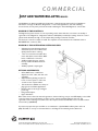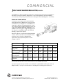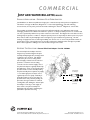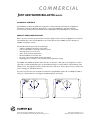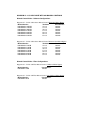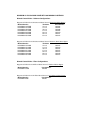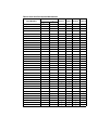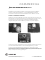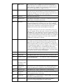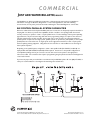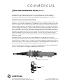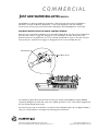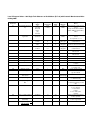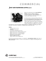
1
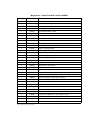
COMMERCIAL
J UST ADD WATER BULLETIN; ISSUE 1
Welcome to the premiere issue of the Just Add Water
bulletin, an Osmonics publication designed to
communicate important product and application
information regarding our newly released Magnum Cv™
commercial and industrial control valve.
The market reaction to this new product introduction has
been outstanding. With backwash rates sufficient to meet
the most demanding filtration and softening applications, the
Magnum Cv promises to be the valve of choice for the
commerical and industrial market segment. Just Add Water
bulletins will be published on a regular basis to ensure your
complete understanding of the Magnum Cv control valve
and its application to the water treatment challenges facing your organization. The following topics will be
addressed in the initial series of bulletins to be published in the forthcoming months:
TOPICS
• System Performance Curves
• Cv Testing
• Backwash Flow Performance
• Part Numbers and Ordering Information
• Magnum Cv Accessories - Drain Line Flow Controls
• Magnum Cv Accessories - Top Stack Distributor
• Magnum Cv Accessories - Side Mount Adapter
• Manufacturing and Test Capabilities
• Magnum Cv Application Notes
• Support and Service Personnel/Resources
If you have any topics that you would like to see addressed in a Just Add Water bulletin, please call us at
(800) 279-9404, Extension 4323, or send your recommendations to the Magnum Cv Marketing Team at the
address listed below.
®
5730 North Glen Park Road Milwaukee, WI 53209 USA
Phone: 262-238-4400, FAX: 262-238-4402, http://www.osmonics.com
© Copyright 2001 Osmonics, Inc.
Printed in the USA PN JAWS 1 Rev. B
COMMERCIAL
J UST ADD WATER BULLETIN; ISSUE 2
MAGNUM Cv™ SINGLE TANK SYSTEMS
Just Add Water is an Osmonics publication designed to communicate important product and application
information regarding our newly released Autotrol® Magnum Cv commercial and industrial control valve.
The Magnum Cv is available in both cost-effective SINGLE
TANK and TWIN ALTERNATING configurations.
The SINGLE TANK configuration is available with
mechanical impulse, or electronic controls.
Magnum Cv Single Tank system Includes:
• Magnum Cv control valve with injector and refill
control. Please specify tank size when ordering.
• 942 mechanical, 952 impulse, or 962 electronic control
for softener or filter application.
• 1-inch or 2-inch flow meter with CPVC, metric CPVC,
NPT brass, or BSPT brass turbine connector with 962
electronic control.
• Time-proven pilot flapper technology.
• Time-proven cartridge diaphragm technology.
• Auxiliary Hydraulic Output Signal.
Optional Accessories:
• CPVC, metric CPVC, NPT brass, or BSPT brass adapters for inlet, outlet, and drain sold separately.
• Optional battery backup provides 72 hours of reserve power to 962 control in case of power failure.
• 12V transformers available in a variety of plug types for worldwide applications.
• Upper Distributor.
• Flanged Tank Adapter.
• Drain Line Flow Control (up to 40 gpm).
• Auxiliary Electrical Switch Output Signal.
If you have any topics that you would like to see addressed in a Just Add Water bulletin, please call us at
(800) 279-9404, or send your recommendations to the Magnum Cv marketing team at Osmonics Autotrol.
®
5730 North Glen Park Road Milwaukee, WI 53209 USA
Phone: 262-238-4400, FAX: 262-238-4402, http://www.osmonics.com
© Copyright 2001 Osmonics, Inc.
Printed in the USA PN 1018068 Rev. C
COMMERCIAL
J UST ADD WATER BULLETIN; ISSUE 3
Just Add Water is an Osmonics publication designed to communicate important product and application
information on design modifications, Magnum Cv™ control valve applications, sales and marketing
announcements, and any other pertinent information affecting the Autotrol® Magnum Cv control valve.
MAGNUM CV TWIN CONTROLS:
The Magnum Cv system assures one unit is providing service water while the second unit is in standby or
regeneration. The Magnum Cv configuration utilizes a 962M (Main) and 962S (Secondary) electronic control
system which eliminates the high cost associated with providing an external controller.
The electronic controls are simple to install. The only field connection between the 962M and 962S is a
PRE-WIRED four conductor cable.
MAGNUM Cv TWIN ALTERNATING SYSTEM INCLUDES:
•
•
•
•
•
2 Magnum Cv twin alternating softener
valves with injectors and refill controls.
Specify tank size when ordering.
1-inch or 2-inch Autotrol turbine flow
meter with CPVC, metric CPVC, BSPT
brass, or NPT brass connectors.
962M and 962S electronic controls.
Factory installed feedback switch kit
assembly.
Auxiliary hydraulic output signal.
OPTIONAL ACCESSORIES
•
CPVC, BSPT brass, or NPT brass
adapters for inlet, outlet, and drain sold
separately.
• Optional battery backup provides 72
hours of reserve power to 962 series
controls in case of power failure.
• 12V transformers available in a variety of
plug types for worldwide applications.
• Drain line flow controls (up to 40 gpm
[151 L/m]).
• Flanged tank adapter.
• Upper distributor.
Either valve can be selected for manual regeneration, if desired. A large, easy-to-read LED display on the 962M
control provides current information on tank in service, capacity remaining (gallons), flow rate, and
regeneration time remaining. The 962M control also keeps accurate historical data in its non-volatile random
access memory (NOVRAM).
If you have any topics that you would like to see addressed in a Just Add Water bulletin, please call us at
(800) 279-9404, or send your recommendations to the Magnum Cv marketing team at Osmonics.
®
5730 North Glen Park Road Milwaukee, WI 53209 USA
Phone: 262-238-4400, FAX: 262-238-4402, http://www.osmonics.com
© Copyright 2001 Osmonics, Inc.
Printed in the USA PN JAWS 3 Rev. C
COMMERCIAL
J UST ADD WATER BULLETIN; ISSUE 4
Just Add Water is an Osmonics publication designed to communicate important product and application
information on design modifications, Magnum Cv™ control valve applications, sales and marketing
announcements, and any other pertinent information affecting the Autotrol® Magnum Cv control valve.
DRAIN LINE FLOW CONTROL
In response to your requests, and consistent with the
design philosophy of the Magnum Cv, we have just made
the installation of your Magnum Cv even EASIER! You no
longer have to plumb an external backwash flow control
into the drain line when installing a Magnum Cv valve. Our
easily installed DRAIN LINE FLOW CONTROL is now
available in sizes from 5 gpm to 40 gpm. Simply place it in
the drain prior to installing the adapter. No additional
plumbing or special tools required.
Osmonics engineers recommend the following backwash
controls. These are standard recommendations and are
provided for your convenience. Backwash flow
requirements may vary with temperature or other
changing conditions.
Media
Tank Size
14”
16”
18”
21”
24”
30”
36”
Std. Softening Resin
(4.5 gpm/ft2)
5 gpm
6 gpm
8 gpm
10 gpm
15 gpm
20 gpm
30 gpm
Fine Mesh Softening
Resin (3.4 gpm/ft2)
4 gpm
5 gpm
6 gpm
8 gpm
10 gpm
15 gpm
25 gpm
Birm, Carbon, Greensand (10 gpm/ft2)
10 gpm
15 gpm
17 gpm
25 gpm
30 gpm
50 gpm
N/A
Neutralizer Multi-Layer
(15gpm/ft2)
16 gpm
20 gpm
25 gpm
35 gpm
50 gpm
75 gpm
N/A
Non-standard drain line flow controls not listed above are also available upon request.
If you have any topics that you would like to see addressed in a Just Add Water bulletin, please call us at
(800) 279-9404, or send your recommendations to the Magnum Cv marketing team at Osmonics.
®
5730 North Glen Park Road Milwaukee, WI 53209 USA
Phone: 262-238-4400, FAX: 262-238-4402, http://www.osmonics.com
© Copyright 2001 Osmonics, Inc.
Printed in the USA PN JAWS 4 Rev. C
COMMERCIAL
J UST ADD WATER BULLETIN; ISSUE 5
PRODUCT/APPLICATION – EXTERNAL PILOT FEED ADAPTER
Just Add Water is an Osmonics publication designed to communicate important product and application
information on design modifications, Magnum Cv™ control valve applications, sales and marketing
announcements, and any other pertinent information affecting the Autotrol® Magnum Cv control valve.
The versatility of the Magnum Cv series product line will inherently place it in applications that provide
challenging conditions for reliable and trouble-free operation. Low-system water pressure is a condition that
can cause operational problems for any water treatment control valve. The Magnum Cv series valves are also
challenged by low pressure conditions. Adequate system pressure is required by the brine injector for proper
brine draw, as well as by the diaphragm valve cartridges for proper activation and positioning. Another
challenge is supply water that contains high turbidity, such as ferric iron or sand. This particulate matter can
foul the pilot screen, reducing pilot pressure, thereby rendering the diaphragm valve cartridges inoperable.
Both of these application challenges can result in above-average service calls.
WE HAVE THE SOLUTION! - External Pilot Feed Adapter Part No. 1040668
The external pilot feed adapter has been
designed to provide the Magnum Cv pilot
assembly and diaphragm valve cartridges with
a separate source of water. The adapter
replaces the pilot screen, sealing off the
internal supply of water from the inlet and
provides a convenient 1/4-inch tubing
connection for the external supply. Use of
the pilot feed adapter is typically dictated by
the application. A low or varying inlet water
pressure situation can be solved by feeding
the pilot assembly from a separate city supply
or a constant high pressure water source,
regulated by a booster pump. Turbidity or
particulate matter in the source water is a
problem that is easily solved by feeding the
pilot water through a 30-micron sediment
cartridge filter and utilizing the external pilot
feed adapter. This way, a clean supply of
water is fed to the pilot assembly and
diaphragm valve cartridges, eliminating the
potential for premature servicing.
External Pilot
Feed Adapter
Pilot Screen
(removed)
®
5730 North Glen Park Road Milwaukee, WI 53209 USA
Phone: 262-238-4400, FAX: 262-238-4402, http://www.osmonics.com
© Copyright 2001 Osmonics, Inc.
Printed in the USA PN JAWS 5 Rev. B
Use and Installation Recommendations:
1.0 Install an external pilot feed adapter on each Magnum Cv valve in the system.
2.0 Install a shut-off valve and a screen/filter in the separate source feed line, if possible. Multi-tank systems
should have a shut-off valve in the feed line to each unit in the system to facilitate servicing.
3.0 Systems with a separate water source located greater than 10 feet from the system should have a water line
of at least 1/2 to 3/4-inch in size, installed to within 6 - 8 feet of the system; then the
1/4-inch tubing can be fed to each Magnum Cv in the system from that point. Again, each feed line should
be provided with a shut-off valve to facilitate servicing.
The pilot feed adapter has been designed to allow the use of the Magnum Cv Series in a multitude of varying
commercial and industrial water treatment applications. Need help with an applications problem? Call
Osmonics – we have the SOLUTION!
COMMERCIAL
J UST ADD WATER BULLETIN; ISSUE 6
SALES AND MARKETING - PARTS LISTS
Just Add Water is an Osmonics publication designed to communicate important product and application
information on design modifications, Magnum Cv™ control valve applications, sales and marketing
announcements, and any other pertinent information affecting the Autotrol® Magnum Cv control valve.
In response to your requests and consistent with our goal to provide the information and documentation
necessary for your Magnum Cv program to be successful, this issue of Just Add Water addresses recommended
spare parts for the Magnum Cv water treatment systems. You will find two separate and distinct lists attached,
directed at specific audiences, that you can use as sales tools.
The first list is “Magnum Cv and Magnum Cv PLUS - Recommended Spare Parts.” This list defines the minimum
spare parts an end user should have on the shelf to maintain an installed system, whether it be a single, twin, or
triple. This list is intended to be used as an end user piece and can be included in a proposal or as part of a
submittal to meet specification requirements.
The second list is “Magnum Cv - Spare Parts Kits”. This extensive parts list defines what you or your dealers
should have in stock to provide rapid service to the end user. This list contains all of the major Magnum Cv
series assemblies for any size filter or softener, thereby providing the ability for immediate response in reacting
to and solving a customer problem.
If you have any topics that you would like to see addressed in Just Add Water, please call us at (800) 279-9404,
or send your recommendations to the Magnum Cv Marketing Team at Osmonics Autotrol.
®
5730 North Glen Park Road Milwaukee, WI 53209 USA
Phone: 262-238-4400, FAX: 262-238-4402, http://www.osmonics.com
© Copyright 2001 Osmonics, Inc.
Printed in the USA P/N JAWS 6 Rev. B
Magnum Cv - Spare Parts Kits Part No. 1040922
Quantity
Part Number
1
1000356
1 1/2-inch Noryl* Adapter Nut
1
1000360
1 1/2-inch Brass Adapter - NPT
1
1000358
1 1/2-inch CPVC Adapter
1
1030664
2-inch Steel Adapter Nut
1
1030663
2-inch Brass Adapter - NPT
1
1030666
2-inch PVC Adapter
1
1000317
Cartridge Assembly - Inlet
1
1000365
Cartridge Assembly - Rinse
1
1000366
Cartridge Assembly - Drain or No Hard Water Bypass (NHWB)
1
1000336
Hard Water Bypass Cap
1
1000342
Auxiliary Switch - 0.1 AMP (Feedback)
6
1013501
Silicone Lubricant Packet
1
1013600
Steel Wrench - Pilot Screen
1
1040691
Valve O-Ring Kit - Inlet, Outlet, Drain, Valve, Dist.
1
1040692
Pilot/Brine Flapper Disc Kit
1
1040669
Injector Kit - Blank (Filter)
1
1040670
Injector Kit - 14-inch Tank
1
1040671
Injector Kit - 16-inch Tank
1
1040672
Injector Kit - 18-inch Tank
1
1040673
Injector Kit - 21-inch Tank
1
1040674
Injector Kit - 24-inch Tank
1
1040675
Injector Kit - 30-inch Tank
1
1040676
Injector Kit - 36-inch Tank
1
1040677
Injector Group Kit - Cap, Cage, and Screen
1
1040679
Flow Control Washer Kit - 14-inch Tank - 3 Pack
1
1040680
Flow Control Washer Kit - 16-inch Tank - 3 Pack
1
1040681
Flow Control Washer Kit - 18-inch Tank - 3 Pack
1
1040682
Flow Control Washer Kit - 21-inch Tank - 3 Pack
1
1040683
Flow Control Washer Kit - 24-inch Tank - 3 Pack
1
1040684
Flow Control Washer Kit - 30-inch Tank - 3 Pack
1
1040685
Flow Control Washer Kit - 36-inch Tank - 3 Pack
1
1040687
Flow Control Group - Cap, Spacer, Holder
1
1040720
Drain Line Flow Control Complete - 5 GPM
1
1040731
Drain Line Flow Control Complete - 26 GPM
*Noryl is a trademark of General Electric Company.
Description
Magnum Cv and Magnum Cv Plus - Recommended Spare Parts*
Quantity
Part Number
Description
15
1006095
Top Plate Screws
5
10006093
Top Plate Screws
2
1000589
Pillow Block Cap
1
1000226
Pilot Screen Assembly
1
1040678
Injector Screen (3-Pack)
1
A (see below)
Injector (Includes O-Rings)
1
A (see below)
Refill Flow Control (3-Pack)
1
1040692
Pilot Flapper Kit w/Springs
1
1040957
Valve O-Ring Kit - Magnum Cv PLUS
1
1040691
Valve O-Ring Kit - Magnum Cv
1
B (see below)
Controller
* Recommended spare parts are sufficient for one to three units.
A - Part number determined by system tank size. (Reference Installation and Service Manual).
B - One spare controller is recommended for multi-tank systems. Order the Main control for twin alternating
system. Consult original invoice or control faceplate for control model.
Note: The addition to the recommended spare parts list of the cartridge assemblies listed below provides in
total the items necessary for a complete control valve rebuild.
Quantity
Part Number
Description
1
1000366
#1 Drain Cartridge
1
1000365
#2 Rinse Cartridge
1
1000366
#3 No Hard Water Bypass Cartridge (if applicable)
1
1000317
#4 Inlet Cartridge
COMMERCIAL
J UST ADD WATER BULLETIN; ISSUE 7
SALES AND MARKETING - MAGNUM Cv SERIES SPECIFICATIONS
Just Add Water is an Osmonics publication designed to communicate important product and application
information on design modifications, Magnum Cv™ control valve applications, sales and marketing
announcements, and any other pertinent information affecting the Autotrol® Magnum Cv control valve.
Sales efforts in the commercial/industrial water treatment market are typically directed at four or five channels
of distribution. One of these channels is the “bid and spec” market, which focuses on new construction and
encompasses institutional (hospital, schools, prisons), manufacturing, office, and housing projects that are
designed by consulting engineering firms. These firms specify the materials to be used on the project that they
know will meet the requirements of both the project and the owner. To ensure that everyone involved in the
project understands what the engineer is requesting each item used in the project carries a specification which
is a detailed list of what the item is, materials of construction, how it will be applied, and how it will operate.
Attached is a sample engineering specification for the Magnum Cv series control valve which can be applied to
either a filter or softener application. The Magnum Cv control valve specification can be adapted into the
system specification, which typically includes the pressure vessels, resin or media, brine tank if applicable, and
performance.
The Magnum Cv control valve specification is not meant to be used in its entirety. It is divided into the main
description (ex. 1.0 main operating valve); standard configuration (ex. 1.1 [standard]); and optional
configuration (ex. 1.1.1 [optional]). Using the main description along with the configuration that best describes
the system being provided, will tailor the specification to the application. Another variation would be to use
either specific sections or phrases of the specification to construct a personalized shortened form.
If you have any questions on using the Magnum Cv control valve specifications or have any topics that you would
like to see addressed in a Just Add Water bulletin, please call us at (800) 279-9404, or send your
recommendations to the Magnum Cv control valve Marketing Team at Osmonics Autotrol.
®
5730 North Glen Park Road Milwaukee, WI 53209 USA
Phone: 262-238-4400, FAX: 262-238-4402, http://www.osmonics.com
© Copyright 2001 Osmonics, Inc.
Printed in the USA P/N JAWS 7 Rev. B
1.0 MAIN OPERATING VALVE
The main operating valve shall be a multiport valve, manufactured of Noryl*, and utilizing integral diaphragm
cartridge assemblies. The cartridge assemblies shall be slow opening and closing, free of water hammer. There
shall be no contact of dissimilar metals within the valve and no special tools shall be required to service either
the valve or the cartridge assemblies. The valve shall be operated hydraulically. The valve shall be provided with
an internal injector to draw brine at a constant rate within a water pressure range of 30 to 100 pounds per
square inch (psi) (2.1 to 6.9 bar). An internal, pressure compensating, refill flow control shall be provided to
ensure a consistent refill of fresh water into the brine tank after regeneration.
The valve tank adapter shall have 4-inch to 8 UN threads of compatible Noryl material that will minimize a
cross thread potential when installed on fiberglass vessels. Commonly serviced components such as pilot
screen, brine injector, and refill control shall be located in the front of the valve for ease of access and to
facilitate servicing.
(standard)
1.1 Single units shall have an automatic bypass of untreated water during regeneration. Conversion to NO
bypass of untreated water during regeneration, after installation, shall be easily accomplished without the
removal or changing of the installed plumbing.
(optional)
1.1.1
The main operating valve shall be provided with an external orifice that allows the pilot assembly
and diaphragm cartridge assemblies to function using a separate source of operating medium
other than the valve inlet water. The external orifice assembly shall be of such design as to permit
field retrofit and to allow the pilot assembly and diaphragm cartridge assemblies to operate equally
using either a hydraulic or pneumatic motive force.
1.2 Valve Connection
Connections to the main operating valve for inlet, outlet, and drain shall be by union nut, adapter, and
O-ring for ease of assembly and installation. The union connection shall be an integral part of the valve.
1.3 Flow Control
A pressure compensating flow control shall be provided in the drain line as close to the main operating
valve as possible to maintain proper backwash and purge rates over wide variations in operating pressure.
The flow control shall require no field adjustment.
1.4 Pilot Control
A multiport pilot control assembly shall be used to position the diaphragm cartridge assemblies as required
by the individual cycles of operation during regeneration and shall be an integral part of the main operating
valve. The pilot control shall operate either hydraulically or pneumatically. The pilot shall be of flapper disc
design with a multiple lobe camshaft assembly to open and close the flapper discs at the proper time to
accomplish the cycles of regeneration. Water to operate the pilot control shall be supplied by the main
operating valve internally.
* Noryl is a trademark of General Electric Company.
(optional)
1.4.1 The pilot control assembly shall provide an external hydraulic signal, capable of operating service
diaphragm valves or other hydraulically controlled devices during the regeneration cycle. by adding
an auxiliary cam to the multiple lobe camshaft assembly.
(optional)
1.4.2 The pilot control assembly shall provide an electrical signal, capable of operating a pump circuit, or
other electrically controlled devices during the regeneration cycle by adding a switch cam to the
multiple lobe camshaft assembly and a microswitch to the main operating valve.
2.0 CONTROL
A factory-mounted controller shall initiate a regeneration, move the multiple lobe camshaft assembly through
an automatic regeneration, and return the operating valve to the service position. The control shall indicate the
cycle of operation at all times. Provision for a manually initiated regeneration shall be provided. In the event of a
power failure, a complete regeneration may be performed by manual operation of the controller or pilot
assembly/multiple lobe camshaft assembly. Variations of the controller/camshaft assembly shall determine
whether the function of the system is a filter (service, backwash, purge cycles) or a softener (service, backwash,
draw/rinse, fast rinse, refill cycles).
(standard)
2.1 An electric time clock controller shall initiate regeneration at any hour of the day and any day of the week.
A dial on the front of the timer clock shall provide for the adjustment of the fresh water refill into the brine
tank which allows for variable salting levels between 6 pounds of salt per cubic foot of resin through 15
pounds of salt per cubic foot of resin. The electric time clock can operate on either 120 vac or 12 vac.
(optional)
2.2 The controller shall be a manual, non-electric type. Initiation of regeneration and length of the
regeneration cycles shall be at the discretion of the water treatment system operator.
(optional)
2.3 The electric controller shall require an electric signal from an external device to initiate a regeneration.
After initiation, the electric controller shall move the multiple lobe camshaft assembly through an
automatic regeneration and return the operating valve to the service position. A dial on the front of the
electric controller shall provide for the adjustment of the fresh water refill into the brine tank which allows
for variable salting levels between 6 pounds of salt per cubic foot of resin through 15 pounds of salt per
cubic foot of resin. The electric controller can operate on either 120 vac or 24 vac.
(optional)
2.4 The electronic controller shall initiate a regeneration based on the volume of water used. In addition, it will
have the capability for a time-bound regeneration initiation, as well as a remote signal input regeneration
initiation. After initiation, the electronic controller shall move the multiple lobe camshaft assembly through
an automatic regeneration and return the operating valve to the service position. An external turbine
meter, installed in the outlet plumbing lines, provides water flow information to the electronic controller.
Push buttons on the front of the electronic controller provide for the programming of 18 controller
parameters that maximize system efficiency. An LED display allows for monitoring of the following
parameters: time of day, time of regeneration, hardness, salt amount, capacity, regeneration time remaining,
unit status, flow, and capacity remaining. The electronic controller shall operate on 12 vac.
The electronic controller shall provide 15 accessible memory locations to assist in troubleshooting the
water treatment system. The contents of the controller memory locations can be examined to determine
the status of the control and the history of water usage. The information can be viewed utilizing the
programming keys on the front of the controller. The electronic controller shall also provide four system
error indicators. These indicators shall be both visual - an ERR message in the LED display on the front of
the control and audible - a BEEP every three seconds. Both alarm indicators shall continue until the error is
corrected.
(optional)
2.5 The electronic control systems shall operate in a twin parallel - triple parallel (choose one) configuration.
All units in the system shall be “on-line,” delivering treated water. When the capacity of a unit within the
system is exhausted, the controller shall automatically take that unit “off-line,” initiate a regeneration cycle,
then place that unit back “on-line” when regeneration is complete. A system interconnect cable between
electronic controllers shall provide an electrical interlock, eliminating the possibility of more than one unit
being in regeneration at a time. All controllers within the system, shall be capable of independent
programming and maintaining the individual water usage history to provide system versatility and
serviceability.
(optional)
2.6 The electronic control system shall operate in a twin alternating configuration with one unit “on-line”
while the other unit is in either “standby” or regeneration. When the capacity of the “on-line” unit is
exhausted, the controller will automatically put the “stand-by” unit “on-line.” The controller then initiates
a regeneration of the unit just taken “off-line” and places that unit in “standby” when the regeneration is
complete. A single electronic control, in conjunction with a remote control, shall provide for the functions
of both the lead and lag units in the system. Programming of both units in the system shall be through the
single electronic control with a factory-provided interconnect cable providing power to and feedback
information from the lag unit to the lead unit. A synchronization program shall be provided as part of the
electronic control software to automatically realign the lead and lag unit, should they become out-of-phase
for any reason.
COMMERCIAL
J UST ADD WATER BULLETIN; ISSUE 8
942 MANUAL CONTROLS
Just Add Water is an Osmonics publication designed to communicate important product and application
information on design modifications, Magnum Cv™ control valve applications, sales and marketing
announcements, and any other pertinent information affecting the Autotrol® Magnum Cv control valve.
PRODUCT DESIGN MODIFICATIONS
We are proud to announce the introduction of another quality control series for the Magnum Cv commercial
and industrial valve. Our new 942 Manual Control series offers both the 942Man 5-cycle softening and
942FMan 3-cycle filter controls.
The 942 Manual Controls provide many advantages:
• Adapts to all Magnum Cv Series control valves
• Low cost alternative to automatic electrical controls
• All components are noncorrosive
• Clean, sleek, professional appearance
• Minimal installation and service time
• No need to turn off inlet water during cycle changes
• Easily upgrades to automatic control should system requirements change
The 942Man and 942FMan faceplates reflect their ease of operation. With clear cycle designations, softener
regeneration or filter backwashing cycles can be initiated through a counterclockwise, manual indexing of the
indicator knob. The application and the operator determine cycle times. Please request our price sheet to aid
you in ordering your 942 Manual Controls.
If you have any topics that you would like see addressed in Just Add Water, please call us at (800) 279-9404, or
send your recommendations to the Magnum Cv Marketing Team at Autotrol.
R
EF
ILL
C
KW
BA
A SH
T
FAS E
S
RIN
ROTATE POINTER
COUNTER
CLOCKWISE
C K W A SH
E
NS
RI
ROTATE POINTER
COUNTER
CLOCKWISE
FAST RINS
E
NE / SLOW
BRI
BA
REGENERATION
COMPLETE
BACKWASH
COMPLETE
PN 1038100 REV 1
PN 1038101 REV 1
®
5730 North Glen Park Road Milwaukee, WI 53209 USA
Phone: 262-238-4400, FAX: 262-238-4402, http://www.osmonics.com
© Copyright 2001 Osmonics, Inc.
Printed in the USA PN JAWS 8 Rev. B
MAGNUM Cv 1-1/2 INCH VALVE WITH 942 MANUAL CONTROLS
Manual Control Valve – Softener Configurations
Magnum Cv 1-1/2 Inch 942 Softener Manual Control With Hard Water Bypass.
Model Number
MG94MNSN-14-HWB
MG94MNSN-16-HWB
MG94MNSN-18-HWB
MG94MNSN-21-HWB
MG94MNSN-24-HWB
MG94MNSN-30-HWB
MG94MNSN-36-HWB
Tank Size
14 inch
16 inch
18 inch
21 inch
24 inch
30 inch
36 inch
Part Number
1046422
1046423
1046424
1046425
1046426
1046427
1046428
Magnum Cv 1-1/2 Inch 942 Softener Manual Control With No Hard Water Bypass.
Model Number
MG94MNSN-14-NHB
MG94MNSN-16-NHB
MG94MNSN-18-NHB
MG94MNSN-21-NHB
MG94MNSN-24-NHB
MG94MNSN-30-NHB
MG94MNSN-36-NHB
Tank Size
14 inch
16 inch
18 inch
21 inch
24 inch
30 inch
36 inch
Part Number
1046429
1046430
1046431
1046432
1046433
1046434
1046435
Manual Control Valve – Filter Configurations
Magnum Cv 1-1/2 Inch 942 Filter Manual Control, Unfiltered Water Bypass.
Model Number
MG94MNFL-UWB
Part Number
1046436
Magnum Cv 1-1/2 Inch 942 Filter Manual Control, No Unfiltered Water Bypass.
Model Number
MG94MNFL-NUB
Part Number
1046436
MAGNUM Cv PLUS 2-INCH VALVE WITH 942 MANUAL CONTROLS
Manual Control Valve – Softener Configurations
Magnum Cv PLUS 2-Inch 942 Softener Manual Control With Hard Water Bypass.
Model Number
MP94MNSN-14-HWB
MP94MNSN-16-HWB
MP94MNSN-18-HWB
MP94MNSN-21-HWB
MP94MNSN-24-HWB
MP94MNSN-30-HWB
MP94MNSN-36-HWB
Tank Size
14 inch
16 inch
18 inch
21 inch
24 inch
30 inch
36 inch
Part Number
1046406
1046407
1046408
1046409
1046410
1046411
1046412
Magnum Cv PLUS 2-Inch 942 Softener Manual Control With No Hard Water Bypass.
Model Number
MP94MNSN-14-NHB
MP94MNSN-16-NHB
MP94MNSN-18-NHB
MP94MNSN-21-NHB
MP94MNSN-24-NHB
MP94MNSN-30-NHB
MP94MNSN-36-NHB
Tank Size
14 inch
16 inch
18 inch
21 inch
24 inch
30 inch
36 inch
Part Number
1046413
1046414
1046415
1046416
1046417
1046418
1046419
Manual Control Valve – Filter Configurations
Magnum Cv PLUS 2-Inch 942 Filter Manual Control, Unfiltered Water Bypass.
Model Number
MP94MNFL-UWB
Part Number
1046420
Magnum Cv PLUS 2-Inch 942 Filter Manual Control, No Unfiltered Water Bypass.
Model Number
MP94MNFL-NUB
Part Number
1046421
COMMERCIAL
J UST ADD WATER BULLETIN; ISSUE 9
Just Add Water is an Osmonics publication designed to communicate important product and application
information on design modifications, Magnum Cv™ control valve applications, sales and marketing
announcements, and any other pertinent information affecting the Autotrol® Magnum Cv control valve.
PRODUCT/APPLICATION - DRAIN LINE FLOW CONTROL
In a continuing effort to bring our customers all of the information required to operate and maintain the
Magnum Cv control valve, tables have been developed which explain how to identify flow rate specifications of
the drain line flow controls from the color of the inserts. Each flow control disk manufactured contains four
color-coded inserts which regulate the flow through the control. Using Table 2, that lists the complete flow
control offering, it is possible to determine in the field the flow rate of the control installed. If the insert
configuration provided does not match any of the standard configurations, Table 1 allows calculation of the flow
control “total flow rate” based on the flow through the individual inserts. For example: a drain line flow control
with two brown, one red, and one green insert would have a flow rate of 28 gpm (7 + 7 + 6 + 8 = 28). The
table also allows for modification of the drain line flow control flow rate by changing the insert configuration.
If you have any topics that you would like to see addressed in a Just Add Water bulletin, please call us at
(800) 279-9404, or send your recommendations to the Magnum Cv marketing team at Osmonics.
Table 1: Drain Line Flow Control Inserts
Part
Number
Flow Rate
gpm m3/h
Color
Quantity
1040763
1040756
1040757
1040758
1040759
1040760
1040761
1040762
0
5
6
7
8
9
10
PVC
Black
Blue
Red
Brown
Green
White
Orange
-
Pack of 25
Pack of 25
Pack of 25
Pack of 25
Pack of 25
Pack of 25
Pack of 25
Pack of 12, with O-ring
0
1.14
1.36
1.59
1.82
2.04
2.27
Disk
®
5730 North Glen Park Road Milwaukee, WI 53209 USA
Phone: 262-238-4400, FAX: 262-238-4402, http://www.osmonics.com
© Copyright 2001 Osmonics, Inc.
Printed in the USA PN JAWS 9 Rev. B
Table 2: Drain Line Flow Control Identification
Part Number
1040720
1040721
1040722
1040723
1040724
1040725
1040726
1040727
1040728
1040729
1040740
1040741
1040742
1040743
1040744
1040745
1040746
1040747
1040748
1040749
1040730
1040731
1040732
1040733
1040734
1040735
1040736
1040737
1040738
1040739
1040750
1040751
1040752
1040753
1040754
1040755
Flow Control Disk
gpm
m3/h
5
6
7
8
9
10
11
12
13
14
15
16
17
18
19
20
21
22
23
24
25
26
27
28
29
30
31
32
33
34
35
36
37
38
39
40
1.135
1.362
1.589
1.816
2.043
2.27
2.497
2.724
2.951
3.178
3.405
3.632
3.859
4.086
4.313
4.54
4.767
4.994
5.221
5.448
5.675
5.902
6.129
6.356
6.583
6.81
7.037
7.264
7.491
7.718
7.945
8.172
8.399
8.626
8.853
9.08
Insert 1 Insert 2 Insert 3 Insert 4
Blue
Red
Brown
Green
White
Blue
Red
Red
Brown
Brown
Blue
Green
White
White
White
Blue
Brown
Green
Green
Red
Green
White
White
Brown
Brown
Orange
Green
Green
Green
Green
White
White
White
Orange
Orange
Orange
Black
Black
Black
Black
Black
Blue
Blue
Red
Red
Brown
Blue
Green
Green
White
Orange
Blue
Brown
Green
Green
Red
Green
White
White
Brown
Brown
Orange
Green
Green
Green
Green
White
White
White
Orange
Orange
Orange
Black
Black
Black
Black
Black
Black
Black
Black
Black
Black
Blue
Black
Black
Black
Black
Blue
Brown
Red
Brown
Red
White
Green
White
Brown
Brown
Orange
Green
Green
Green
Green
White
White
White
Orange
Orange
Orange
Black
Black
Black
Black
Black
Black
Black
Black
Black
Black
Black
Black
Black
Black
Black
Blue
Black
Black
Black
Red
Black
Black
Black
Brown
Green
Black
Brown
Green
White
Orange
Green
White
Orange
Green
White
Orange
COMMERCIAL
J UST ADD WATER BULLETIN; ISSUE 10
Just Add Water is an Osmonics publication designed to communicate important product and application
information on design modifications, Magnum Cv™ control valve applications, sales and marketing
announcements, and any other pertinent information affecting the Autotrol® Magnum Cv control valve.
MAGNUM Cv PROGRAMMING PARAMETERS
The Magnum Cv control valve is available with several controller options, making it the most versatile on the
market. Controller options include the 942 mechanical control, the 952QC quick-connect impulse control, and
the 962 electronic control, which supports single, twin alternating, twin parallel and triple parallel
configurations. All single tank controls are available in 5-cycle softener or 3-cycle filter configurations.
942 Mechanical Control
952 QC Impulse Control
962 Electronic Control
The 962 electronic controller can be programmed to meet your specific water treatment needs. In response to
your requests, the following table explains each of the 962 programming parameters, or “P-values”.
To enter the “P-value” programming mode, press and hold the up (↑) and down (↓) arrow keys
simultaneously for three seconds. A “P” will appear in the display. If you do not enter a value within 30 seconds,
the program will exit the P-value mode automatically. If this happens, simply press and hold down the up (↑) and
down (↓) arrow keys and re-enter the programming mode.
®
5730 North Glen Park Road Milwaukee, WI 53209 USA
Phone: 262-238-4400, FAX: 262-238-4402, http://www.osmonics.com
© Copyright 2001 Osmonics, Inc.
Printed in the USA P/N JAWS 10 Rev. B
LEVEL II P-Values for the 962 Single Tank Control
P1 *
Time of Day
Current time of day
P2 *
Time of
Regeneration
If P15 is set at 0 (variable reserve), the unit will check at the P2 time to
see if the variable reserve capacity has been reached. If it has, the unit
WILL regenerate at the specified P2 time. If the capacity display reaches
zero gallons (m3) at any time during the day, the unit will NOT
regenerate until the specified P2 time is reached.
If P15 is set at 1 (fixed reserve), the unit will check at the P2 time to see
if the fixed reserve capacity (P16) has been reached. If it has, the unit
WILL regenerate at the specified P2 time. If the capacity display reaches
zero gallons (m3) at any time during the day, the unit will NOT
regenerate until the specified P2 time is reached.
If P15 is set at 2 (variable reserve with immediate regen), the unit will
check at the P2 time to see if the variable capacity has been reached. If it
has, the unit will regenerate at the specified P2 time. If the capacity
display reaches zero gallons (m3) at any time during the day, the unit
WILL regenerate immediately. It will ALSO continue checking at the
specified P2 time to see if the variable reserve capacity has been reached,
initiating a regeneration at the P2 time if it has.
If P15 is set at 3 (fixed reserve with immediate regen), the unit will check
at the P2 time to see if the fixed reserve capacity has been reached. If it
has, the unit will regenerate at the specified P2 time. If the capacity
display reaches zero gallons (m3) at any time during the day, the unit
WILL regenerate immediately. It will ALSO continue checking at the
specified P2 time to see if the fixed reserve capacity has been reached,
initiating a regeneration at the P2 time if it has. If the fixed reserve is set
to zero, the unit will ONLY regenerate when the capacity display reaches
zero.
If calendar override is used (P14), the unit will regenerate every 1 to 30
days at the specified P2 time.
Fixed Reserve: Fixed percentage of capacity defined by user
(gallons)(m3).
Variable Reserve: 120% of the daily average (gallons)(m3) calculated
from historical values stored in NOVRAM.
P3 **
Hardness of water
If the 962 controller is programmed at P12 to use U.S. units, enter
hardness in grains per gallon (gpg). If the 962 controller is programmed
at P12 to use metric units, enter hardness in parts per million (ppm).
P4 **
Salt amount
Enter your TOTAL salt amount per regeneration. For example, salting at
10 lb (4.5 kg) per cubic foot on a unit with 3 cubic feet of resin, enter 30.
(10 lb/ft3) x (3 ft3)= 30 lb. salt. [(4.5 kg/ ft3) x (3 ft3)= 13.6 kg salt].
P5
Capacity of unit
Enter the capacity of the unit here, in kilograins (kilograms). For
example, a 3 ft3 unit with a resin capacity of 25,000 grains (1620 grams)
per ft3, enter 75 here. (25,000 grains/ ft3) x (3 ft3) = 75,000 grains = 75
kilograins. [(1620 grams/ ft3) x (3 ft3) = 4860 grams = 4.86 kilograms].
Note: 15 lb/cu ft salting yields 30,000 grains/cu ft resin
10 lb/cu ft salting yields 25, 000 grains/cu ft resin
6 lb/cu ft salting yields 20,000 grains/cu ft resin
Reduced salting yields a reduced capacity
1 kilograin (1000 grains) = 0.0648 kilograms (64.8 grams)
P6
Refill control
Enter value from chart on Refill Control Performance Data page of
manual. This value is the refill flow rate times 10, rounded to the next
whole number. For example, on a 21-inch tank, the refill control has a
flow rate of 1.5 gpm. Enter 15 (1.5 gpm x 10 = 15).
P7
Brine draw rate
Enter value from chart on Injector Performance Data page of manual.
This is the injector draw rate times 10, rounded to the next whole
number. For example, on a 21-inch tank, the injector has a draw rate of
0.85 gpm. Enter 9 (0.85 gpm x 10 = 8.5, rounded up to 9).
P8
Not used
P8 is reserved for future use.
P9
Backwash time
Self explanatory. Generally, 5 to 15 minutes or until water runs clear or
specific water conservation needs are met.
P10
Slow rinse
Time, in minutes, to achieve adequate slow rinse volume for resin type
used. Resin manufacturers recommend one to two and one half bed
volumes of slow rinse water. The required amount of time is calculated
using the injector performance curves provided in the back of the
Magnum Cv Performance Data manual available from Osmonics.
For example, assuming 9 ft3 of resin and one bed volume of slow rinse
water for a 24-inch x 72-inch tank, enter 17 minutes. (9 ft3) x (7.48 gal/
ft3)(0.028 m3/ ft3) = 67.3 gal (0.26 m3). From injector performance curves
for a 24-inch tank at 60 psi (4.14 bar), expect a 4 gallon per minute (0.9
m3)/hr flow rate through the injector after brine draw ends. 67.3 gallons/
4 gpm = 16.8 minutes, rounded up to 17 minutes. (0.26 m3/0.9m3/hr =
16.8 minutes, rounded up to 17 minutes.
P11
Fast rinse
Time, in minutes, to achieve adequate purge volume for resin type used.
For example, for standard softening resin (Ionac C-249), purge at 30
gallons (0.11 m3) per cubic foot of resin. A unit with 3 ft3 of resin will
require 90 gallons (0.34 m3) of water to obtain the resin manufacturer’s
recommended purge. (30 gal/ ft3 x 3 ft3) = 90 gallons. (0.11 m3/ ft3 x 3 ft3
= 0.34 m3). The purge flow rate is controlled by the drain line flow
control. For this example, assume a 5 gpm (1.14 m3/hr) drain line flow
control. Enter 18 minutes in P10. (90 gallons/5 gpm) = 18 minutes (0.34
m3/1.14 m3 /hr = 0.3 hr/ x 60 min = 18 minutes).
P12
Units of measure
Self explanatory. Enter 0 for U.S., enter 1 for metric.
P13
Clock mode
Self explanatory. Enter 0 for 12-hour clock, enter 1 for 24-hour clock.
P14
Calendar override
0 = No calendar override. 1 - 30 = Maximum number of days between
regeneration/backwash.
P15
Reserve type
See P2.
Immediate or delay
regeneration
P16 ***
Fixed Reserve
capacity
If P15 is set at 1 or 3, enter the fixed reserve capacity (in gallons) (m3)
that the unit will look for as explained in sections P2 and P15 above.
P17
Operation type
Self explanatory. 0 = single or parallel tank; 2 = twin alternating.
P18
Salt/capacity
lockout
Allows for the lock out of P4 and P5 so that NO unauthorized changes
to the programmed values can be made.
P19
Turbine size
Self explanatory. 1 = 1.0-inch turbine; 2 = 2.0-inch turbine; 1.5 = 1.5-inch
flow sensor; 3 = 3.0-inch flow sensor.
P20
Factory use only
Factory use only. Do not attempt to enter a value. If a number is
entered, other programming parameters will be changed.
* The 962 controller functions in either a 12-hour or 24-hour clock mode. Programming P13 (clock mode)
before P1 or P2 will eliminate any confusion when setting these parameters.
** The 962 controller functions in either U.S. or metric units. Programming P12 (units of measure) before P3 or
P4 will eliminate any confusion when setting these parameters.
*** The calculated gallon amount loaded into the daily registers (L7 through L13) at START-UP, uses this
percentage of capacity. Example: 90,000 grains in P5 ñ 10 grains in P3, 90,000 / 10 = 9,000 gallon capacity. 9,000
x .3 (30% in P16) = 2700 gallons, which is loaded into L7 through L13, the daily averages. For this example, the
variable reserve at START-UP, would be 2700 gallon x 1.2 (120% of the daily average) = 3240 gallon. This daily
average will change as actual water usage information is gathered.
If you have any topics that you would like to see addressed in Just Add Water, please call us at (800) 279-9404 or
send your recommendations to the Magnum Cv marketing team at Osmonics.
COMMERCIAL
J UST ADD WATER BULLETIN; ISSUE 11
Just Add Water is an Osmonics publication designed to communicate important product and application
information on design modifications, Magnum Cv™ control valve applications, sales and marketing
announcements, and any other pertinent information affecting the Autotrol® Magnum Cv control valve.
962 CONTROL PARALLEL SYSTEM CAPABILITIES
Osmonics realizes that increased system flexibility and ease of conversion are frequently required in the field. In
keeping with our efforts to provide these capabilities, all 962 controllers come packaged with the internal
circuitry necessary to operate in a twin- or triple- parallel mode. To take advantage of this system-expanding
upgrade feature, only an interconnecting cable and minor programming changes are required. An electronic
interlock, designed into the 962 controller, assures that only one unit at a time can regenerate within the
parallel system. Compared to the single system, parallel systems can provide two (twin parallel) or three (triple
parallel) times the service flow rate. A single system can be upgraded in the field to a twin or triple system
without replacing existing equipment. Using Autotrol 962 controllers on new installations sets the stage for
future system expansion.
Depending on the parallel system configuration, either a twin-parallel cable (PN 1034312, list $22.00) or a
triple-parallel cable (PN 1035587, list $42.00) will be required. Conversion to the parallel configuration is
accomplished by linking the four pin connectors of each 962 control in the system to the appropriate
interconnect cable. The controllers then require reprogramming using the parameters listed in the Magnum Cv
control valve manual.
If you have any topics that you would like to see addressed in Just Add Water, please call us at (800) 279-9404, or
send your recommendations to the Magnum Cv marketing team at Osmonics.
Magnum Cv Series Parallel Operation
TM
4
OPTIONAL
B
A
T
3
4
FLOW
1
Magnum Cv 962
2
OPTIONAL
B
A
T
3
Magnum Cv 962
4
OPTIONAL
FLOW
3
1
2
Magnum Cv 962
B
A
T
FLOW
1
2
2
PARALLEL SYSTEM CONNECTION PROCEDURE
1
2
3
4
Connect tubine flow meters.
Connect interlock cables.
Attach optional batteries.
Plug transformers into outlets on common circuit.
®
5730 North Glen Park Road Milwaukee, WI 53209 USA
Phone: 262-238-4400, FAX: 262-238-4402, http://www.osmonics.com
© Copyright 2001 Osmonics, Inc.
Printed in the USA PN JAWS 11 Rev. B
COMMERCIAL
J UST ADD WATER BULLETIN; ISSUE 12
Just Add Water is an Osmonics publication designed to communicate important product and application
information on design modifications, Magnum Cv™ control valve applications, sales and marketing
announcements, and any other pertinent information affecting the Autotrol® Magnum Cv control valve.
CAMSHAFT PRODUCT DESIGN MODIFICATIONS
As part of our continuing effort to provide the highest quality products, a modification has been made to the
number three green cam lobe ( P/N 1001622 ) on the Magnum Cv series camshaft. This modification was made
to assure a continuous flow of conditioned water while one unit transitions from Stand-by to Service and the
other unit begins a regeneration cycle. Reports from the field indicate that on rare occasions, the drive motor
on the unit moving from “Stand-by” to “On-line” would stop before the number 3 pilot flapper closed. When a
unit is in “Stand-by”, the number 3 pilot flapper keeps the No Hard Water Bypass cartridge closed, preventing
service flow. With the unit in “Service”, the number 3 pilot flapper must close, which releases the No Hard
Water Bypass cartridge, allowing service flow. The modification to the number three green cam lobe closes the
number 3 pilot flapper early in the transition from “Stand-by” to “Service”. A groove has been machined
lengthwise on the keyway of the new cam lobe (see illustration below ) to easily distinguish the modified cam
lobe from the original.
The modified number 3 green cam lobe is in stock and available for order. All Magnum Cv series twin
alternating systems manufactured after March 8, 1999 utilize the new modified cam lobe. If any installed systems
have experienced a “ no water to service “ condition, we recommend replacing the number 3 green cam lobe
on both control valves, on those and all other systems installed on critical water applications. Replacement cam
lobes will be provided at no charge for all systems shipped prior to March 8, 1999.
If you have any topics that you would like to see addressed in Just Add Water, please call us at (800) 279-9404 or
send your recommendations to the Magnum Cv Marketing Team at Osmonics.
Number 3 “Green” Cam
;;
Groove
®
5730 North Glen Park Road Milwaukee, WI 53209 USA
Phone: 262-238-4400, FAX: 262-238-4402, http://www.osmonics.com
© Copyright 2001 Osmonics, Inc.
Printed in the USA PN JAWS 12 Rev. B
COMMERCIAL
J UST ADD WATER BULLETIN; ISSUE 13
Just Add Water is an Osmonics publication designed to communicate important product and application
information on design modifications, Magnum Cv™ control valve applications, sales and marketing
announcements, and any other pertinent information affecting the Autotrol® Magnum Cv control valve.
Diaphragm Cartridge O-Ring Improvement
A product modification was made to the Magnum Cv Series control valve cartridge assemblies on June 15,
1999. The O-ring seal on the pressure/vent ports of all Magnum Cv diaphragm cartridges was changed from a
face seal to a radial seal design. This modification provides superior sealing characteristics between the
pressure/vent nipples on each diaphragm cartridge and the mating ports in the principle valve body (Figure 1).
The new O-ring seal is a direct replacement for the original O-ring seal and will function properly in all Magnum
Cv Series control valves irrespective of manufacture date. To accommodate the new O-ring design, the
diaphragm cartridge was slightly modified by removing the step from around the pressure/vent nipples
(Figure 2). Only the cartridges need to be paired with the correct O-ring. Cartridges manufactured on or
before 6/14/99 use a 1/4 x 1/16 O-ring - PN 1010103. Cartridges manufactured after 6/14/99 use a 7/32 x 3/32
O-ring - PN 1010116. See Figure 3 for size comparison. All valves can use either cartridge.
If there are any questions regarding this product improvement, please contact Osmonics Customer Service at
(800) 837-9101, extension 4336.
New Style Hard
Water Bypass Cap
Showing partial view
with new fat O-ring
seals.
Note: No step under
the nipple.
Pressure/Vent Nipples
Old Style Hard
Water Bypass Cap
Figure 1
Showing partial view
with skinny O-ring
seals.
Actual Size
Note: Step under
the nipple.
New Style
P/N 1010116
Old Style
P/N 1010103
Figure 3
Figure 2
Note: Modification applies to all cartridges. Hard
water bypass cap is illustrated as an example of
the modification.
®
5730 North Glen Park Road Milwaukee, WI 53209 USA
Phone: 262-238-4400, FAX: 262-238-4402, http://www.osmonics.com
© Copyright 2001 Osmonics, Inc.
Printed in the USA PN JAWS 13 Rev. B
COMMERCIAL
J UST ADD WATER BULLETIN; ISSUE 14
Just Add Water is an Osmonics publication designed to communicate important product and application
information on design modifications, Magnum Cv™ control valve applications, sales and marketing
announcements, and any other pertinent information affecting the Autotrol® Magnum Cv control valve.
CAM SHAFT MODIFICATION FOR SIMPLE CONTROL REMOVAL
Osmonics has recently made modifications to the camshaft and pillow block caps of the Autotrol Magnum Cv
valve that make it easier to engage and disengage the control assembly to the valve. Notice that on the
illustration below the new alignment arrows on the camshaft and pillow block cap are in line with each other.
In this position the camshaft can be engaged or disengaged from the control assembly with ease.
Camshaft Arrow
Pillow Block Arrow
The camshaft and pillow block caps will retain the same part numbers, (P/N 1000341) and (P/N 1000589)
respectively. All Magnum Cv valves with a date code of 28799, October 14, 1999, or later will be equipped with
the new camshaft and pillow block caps.
If you have any topics that you would like to see addressed in Just Add Water, please call us at (800) 279-9404, or
send your recommendations to the Magnum Cv marketing team at Osmonics.
®
5730 North Glen Park Road Milwaukee, WI 53209 USA
Phone: 262-238-4400, FAX: 262-238-4402, http://www.osmonics.com
© Copyright 2001 Osmonics, Inc.
Printed in the USA PN JAWS 14 Rev. B
COMMERCIAL
J UST ADD WATER BULLETIN; ISSUE 15
Just Add Water is an Osmonics publication designed to communicate important product and application
information on design modifications, Magnum Cv™ control valve applications, sales and marketing
announcements, and any other pertinent information affecting the Autotrol® Magnum Cv control valve.
MAGNUM Cv TWIN-TANK CONVERSIONS
In response to your requests we are publishing a list of parts to easily convert a Magnum single tank system to a
twin-alternating system. This list is made with the assumption that two valves, tanks, etc., are in place. If the
conversion is to upgrade a single to a twin-alternating system, then a single Magnum Cv valve with a 962M
control should be ordered along with a 962S control, one switch kit P/N 1041049, and a twin-alternating
camshaft assembly P/N 1001751.
Magnum Single System to Twin Alternating Conversion Parts List
Qty.
Part Number
Description
1
1
2
2
Twin Alternating Softener 60 Hz
1046328
Electronic Control/962M Main/12 VAC/60 Hz
1046330
Electronic Control/962S Secondary/12 VAC/60 Hz
1001751
Twin Alternating Camshaft Assembly
1041049
Switch Kit Assembly 0.1 amp rating
1
1
2
2
Twin Alternating Softener 60 Hz with Battery Backup
1046329
Electronic Control/962M Main/12 VAC/Battery Backup 60 Hz*
1046330
Electronic Control/962S Secondary/12 VAC/60 Hz
1001751
Twin Alternating Camshaft Assembly
1041049
Switch Kit Assembly 0.1 amp rating
1
1
2
2
Twin Alternating Softener 50 Hz
1046861
Electronic Control/962M Main/12 VAC/50 Hz
1046863
Electronic Control/962S Secondary/12 VAC/50 Hz
1001751
Twin Alternating Camshaft Assembly
1041049
Switch Kit Assembly 0.1 amp rating
1
1
2
2
Twin Alternating Softener 50 Hz with Battery Backup
1046862
Electronic Control/962M Main/12 VAC/Battery Backup 50 Hz*
1046863
Electronic Control/962S Secondary/12 VAC/50 Hz
1001751
Twin Alternating Camshaft Assembly
1041049
Switch Kit Assembly 0.1 amp rating
*Does not include battery
1007201
Battery
1009097
Battery Cap
1000396
Battery Bracket
If you have any topics that you would like to see addressed in Just Add Water, please call us at (800) 279-9404,
or send your recommendations to the Magnum Cv marketing team at Osmonics.
®
5730 North Glen Park Road Milwaukee, WI 53209 USA
Phone: 262-238-4400, FAX: 262-238-4402, http://www.osmonics.com
© Copyright 2001 Osmonics, Inc.
Printed in the USA PN JAWS 15 Rev. B
COMMERCIAL
J UST ADD WATER BULLETIN; ISSUE 16
Just Add Water is an Osmonics publication designed to communicate important product and application
information on design modifications, Magnum Cv™ control valve applications, sales and marketing
announcements, and any other pertinent information affecting the Autotrol® Magnum Cv control valve.
ANNOUNCING THE 1-1/2 INCH BRASS ADAPTER WITH 2 INCH FLANGE IN NPT AND BSP
THREAD
The 1-1/2 inch Brass Adapter with 2-inch flange is available. This enables a quick and convenient method of
reducing from a 2-inch turbine to a 1-1/2 inch pipe. This will also allow the easy adaptation of the Magnum Cv
Plus 2-inch inlet and outlet connections to 1-1/2 inch plumbing. The price is the same as a standard 2-inch brass
adapter. This may be ordered through Customer Service.
1-1/2 Inch Brass Adapter, P/N 1030709
Part Numbers
1.5-Inch Brass Adapter with 2-Inch Flange
NPT
1030709
BSP
1031248
2-Inch Flow Meter with Adapters*
1041170
1041171
Adapters without Flow Meter*
1041168
1041169
1041208
1041209
Magnum Cv PLUS Adapter Kit - Brass NPT for Inlet, Outlet, Drain*
* Includes adapter nuts and gaskets.
If you have any topics that you would like to see addressed in Just Add Water, please call us at (800) 279-9404,
or send your recommendations to the Magnum Cv marketing team at Osmonics.
®
5730 North Glen Park Road Milwaukee, WI 53209 USA
Phone: 262-238-4400, FAX: 262-238-4402, http://www.osmonics.com
© Copyright 2001 Osmonics, Inc.
Printed in the USA Jaws16 Rev. A
COMMERCIAL
J UST ADD WATER BULLETIN; ISSUE 17
Just Add Water is an Osmonics publication designed to communicate important product and application
information on design modifications, Magnum Cv™ control valve applications, sales and marketing
announcements, and any other pertinent information affecting the Autotrol® Magnum Cv control valve.
Osmonics is pleased to announce a major upgrade to the already versatile 962 electronic control. All
962 controls shipped after August 15, 2000 will have the latest software version.
The new features include:
• All 962 family controls are now battery back-up capable. A 9-volt rechargeable battery may be ordered
from Osmonics as a separate line item, P/N 1075768. A standard 9-volt Alkaline may be used as a
temporary supply.
• The capability to support a much broader array of flow sensors. This includes the standard Autotrol 1-inch
and 2-inch turbines as well as Data Industrial, Signet, Badger Meter, and other contacting head flow meters.
The new capability is done through the addition of user defined K-factors or pulse equivalents.
• A remote start regeneration input that may be programmed to qualify a dry contact start signal from a variety
of devices including a differential pressure switch or a signal switch in a sequential filter bank.
• Day of Week regeneration. It is now possible to program individual days that the system will regenerate.
When programmed, this feature will override the demand regeneration and will reset capacity remaining
upon completion of the regeneration. This feature ensures that a regeneration will occur on programmed
days. All other times the system will operate as a demand system.
• When the Time of Day is programmed the user will also program which day it is. Sunday = 1, Monday = 2,
Tuesday = 3, etc. This feature makes it easier to look at the average daily water usage data in the History
Data table.
These features, along with all the standard capabilities of the 962 control family, are also now available in our
new AquaMatic® 962 Stager control.
If you have any topics that you would like to see addressed in Just Add Water, please call us at (800) 279-9404,
or send your recommendations to the Magnum Cv marketing team at Osmonics.
®
5730 North Glen Park Road Milwaukee, WI 53209 USA
Phone: 262-238-4400, FAX: 262-238-4402, http://www.osmonics.com
© Copyright 2001 Osmonics, Inc.
Printed in the USA P/N JAWS 17 Rev. B
P1 - Day of Week Programming
The day of the week is now displayed with the time of day in the far left digit. It is programmed at P1 the same
as the time of day. The shift key will move the flashing digit to the far left digit skipping the blank digit between
time of day and day of week. The day of week will automatically increment at midnight. This change will allow
customers to correlate the daily usage history stored in L7 through L13 to days of the week. Customer should
use day 1 = Sunday through day 7 = Saturday. Then L7 will hold the usage history for Sunday through L13
holding the usage history for Saturday. The daily averages stored in the L-values will still be updated at the time
of regeneration not midnight. This is required to keep an accurate record for reserve capacity needed at the
time of regeneration. Customers should understand that the L-value displayed for the average water usage for
Sunday “day one” will be the average water usage for Sunday at 2:00 AM to Monday at 2:00 AM. Assuming the
time of regeneration is set for 2:00 AM. Customers can reduce this error by setting the time of regeneration to
12:01 AM.
P19 - Flow Sensor Select
P19 will not show 1.0, 1.5, 2.0, 3.0 for flow sensor sizes as before. P19 will now show “1” for Autotrol 1 inch
turbine, “2” for Autotrol 2 inch turbine, “3” for user programmable K-factor, and “4” for user programmable
pulse equivalent. The K-factors or Pulse equivalents for individual meters should be supplied by the respective
meter manufacturer. The control is no longer preprogrammed for the Data Industrial 1.5 inch and 3.0 inch flow
sensors. The default value is “2” for use with the Autotrol 2 inch turbine.
P20 - K-factor or Pulse Equivalent
P20 is now used for user defined K-factor or pulse equivalent. The range is 000.01 to 255.00 in 0.01 steps. How
this number is used is defined by the values stored in P12 (units of measure) and P19 (flow sensor select). P12
is used to define gallons or liters (0 = gallons, 1 = liters). P19 is used to define K-factor or pulse equivalent
(3 = K-factor, 4 = pulse equivalent). K-factor is defined as pulses per gallon or pulses per liter. Signet and
Sea-Flow are two flow sensor manufactures that publish a K-factor. The control can now use any flow sensor as
long as the programmed K-factor is correct. The pulse equivalent is defined as gallons or liters per pulse. The
control will register 5 gallons of flow for every pulse if P12 = 0, P19 = 4 and P20 = 5.00. Badger meter is one
manufacturer that uses a pulse equivalent. The control will now show flow rate if P19 = 4 (pulse equivalent).
This is because pulses are accumulated over 10 seconds and flow rate is displayed in gallons per minute. The
control will always alternate between time of day and capacity remaining or regeneration time remaining.
P21 - Remote Regeneration Delay
P21 is used to program the delay time for the remote regeneration start. The range is 1 to 254 seconds in
1 second steps. The default is 60 seconds. This function was added because customers are connecting
differential pressure switches to this input. A counter starts when the conductors of this input are connected
with a dry contact closure. A regeneration will start when the conductors remain connected for the
programmed time. The counter will reset to zero when the connection is broken for at least 0.02 seconds. The
remote regeneration input cannot be used to perform a double manual regeneration. The remote regeneration
input will be ignored when the control is doing a regeneration.
Regeneration Cycle Advance
A function was added to advance the control to the next stop position during a regeneration. Pressing and
holding the left arrow key will cause the control to advance to the next stop position of the regeneration. The
regeneration time remaining will decrease by the amount of stop time that was skipped. This function will not
work when the motor is on. The control will beep if the left arrow key is held for 2.5 seconds and the motor
output is on. The control would not stop in the correct position if time was skipped during a motor on time of
the regeneration.
Battery Backup Option
All 962 family controls are now battery backup capable. There is a door in the backplate that allows access to
the battery harness. A 9 volt rechargeable battery is available from Osmonics PN 1075768. The battery is a
VARTA, TYPE V7/8H (AccuPlus Nickel Hydride Ni-mh 9v 150 mAH, No. 5522). A standard non-rechargeable
battery is an option for backup but needs to be replaced periodically.
LEVEL IV - Day of Week Regeneration
It is now possible to program individual days that the system will regenerate regardless of water usage. When
programmed, this feature will override the demand regeneration and will reset capacity remaining upon
completion of the regeneration. This feature insures that a regeneration will occur on programmed days. All
other times the system will operate as a demand system. Level IV must be accessed to program Day of
Regeneration. Simultaneously press the LEFT and DOWN arrow buttons for 3 seconds to gain access and then
press the UP or DOWN arrow buttons until the desired Day location (1-7) is displayed. Press the LEFT arrow
button to display value in the location, 0 = no Regeneration - 1 = Regeneration. To program a regeneration for
a specific day, go to that day and change the 0 to1. A regeneration will occur at the time that is programmed
into P2. A regeneration will occur every week on the day(s) that is (are) programmed with a 1.
Level II Program Values - 962 Twin Tank Alternating Softeners (P17 = 2) with Controls Manufactured After
09 Aug 2000
Description
Range of
Values
Minimum
Increment
Factory
Value
Units of
Measure
P1
Day of Week and Time of
Day
(1-7)
1:00-12:59
AM or PM
Metric (1-7)
0:00 - 23:59
(1 day)
1 minute
None
Hour
Minute
Range depends on value selected
for P13
For day of week SUN=1, MON=2,
TUE=3, WED=4, THU=5, FRI=6,
SAT=7.
P2
Time of day to start
regeneration
1:00-12:59 AM or PM
00:00-23:59
1
None
Hour
Minute
Range depends on value selected
for P13. Use only if P15 = 0 or 1
P3
Hardness of water
3-250
30-2500
1
10
0
0
Grains per
Gallon ppm
Unit of measure depends on value
selected for P12
P4
Salt amount
5-1250
2-500
5
2
10
4
Pounds
Kilograms
Unit of measure and default
depends on value selected for P12
P5
Capacity of unit
1-2600
0.1-260.0
1
0.1
0
Kilograins
Kilograms
Total capacity for each tank. Unit of
measure depends on value selected
for P12
P6
Refill controller
2-99
1
0
Selected from chart in Performance Data Sections
P7
Brine draw rate
2-99
1
0
Selected from chart in Performance Data Sections
Parameter
Notes
P9
Backwash time
4-30
1
14
P10
Rinse time
7-125
1
40
Minutes
P11
Purge time
2-19
1
4
Minutes
P12
Units of measure
0-1
1
0
0 = US
1 = Metric
P13
Clock mode
0-1
1
0
0 = 12 hour clock
1 = 24 hour clock
P14
Calendar override
0-30
1
0
P15
Regeneration delay
0-1
1
0
P16
Capacity that must be left
on 2nd tank to permit
delayed regeneration of 1st
tank
0-70
1
30
P17
Operation type
0-2
1
2
0 = Single or Parallel
2 = Twin Alternating
P18
Salt/Capacity Change Lock
Out
0-1
1
0
0 = None
1 = Salt/Capacity Change Locked
Out
P19
Flow Sensor Select
1
1 = 1.0” Autotrol
2 = 2.0” Autotrol
3 = User defined
K-factor
4 = User defined
pulse equivalent
P20
K-factor or Pulse Equivalent
0.00-255.00
.01
0.01
Number used for Meter K-factor
or Pulse equivalent
P21
Remote Regeneration
Switch Delay
0-254
1
60
P22
Factory Use Only - DO
NOT CHANGE
9
Minutes
Days
0 = No calendar override
0 = Immediate regeneration
1 = Regeneration delayed until time
programmed in P2 is reached
Percent of
Total Capacity
Seconds
Used only if P is set to 1
Time remote switch must be active
to start a regeneration
Level II Program Values - 962 Single Tank Softeners or Dealkalizers (P17 = 0) with Controls Manufactured After
09 Aug 2000
Description
Range of
Values
Minimum
Increment
Factory
Value
Units of
Measure
P1
Day of Week and Time of
day
(1-7)
1:00-12:59
AM or PM
Metric
(1-7)
0:00-23:59
(1 day)
1 minute
None
Hour
Minute
Range depends on value selected
for P13
For day of week SUN=1, MON=2,
TUE=3, WED=4, THU=5, FRI=6,
SAT=7
P2
Time of day to start
regeneration
1:00-12:59 AM or PM
00:00-23:59
1
None
Hour
Minute
Range depends on value selected
for P13
Use only if P15 = 0 or 1
P3
Hardness of water
3-250
30-2500
1
10
0
0
Grains per
gallon ppm
Unit of measure depends on value
selected for P12
P4
Salt amount
5-1250
2-500
5
2
10
4
Pounds
Kilograms
Unit of measure and default
depends on value selected for P12
P5
Capacity of unit
1-2600
0.1-260.0
1
0.1
0
Kilograins
Kilograms
Unit of measure depends on value
selected for P12
P6
Refill controller
2-99
1
0
Selected from chart in Performance
Data Sections
P7
Brine draw rate
2-99
1
0
Selected from chart in Performance
Data Sections
P9
Backwash time
4-30
1
14
Minutes
P10
Rinse time
7-125
1
40
Minutes
P11
Purge time
2-19
1
4
Minutes
P12
Units of measure
0-1
1
0
0 = US
1 = Metric
P13
Clock mode
0-1
1
0
0 = 12 hour clock
1 = 24 hour clock
P14
Calendar override
0-30
1
0
P15
Reserve Type
0-3
1
0
P16
Initial average usage or
fixed reserve
0-70
1
30
P17
Operation type
0-2
1
0
0 = Single or Parallel
2 = Twin Alternating
P18
Salt/Capacity Change Lock
Out
0-1
1
0
0 = None
1 = Salt/Capacity Change Locked
Out
P19
Flow Sensor select
P20
K-factor or Pulse equivalent
0.00-255.00
.01
0.01
P21
Remote Regeneration
Switch Delay
0-254
1
60
P22
Factory Use Only - DO
NOT CHANGE
Parameter
Days
Notes
0 = No calendar override
See Selectable Reserve Options
page 29 in Manual
Percent of
Total capacity
1 = 1.0” Autotrol
2 = 2.0” Autotrol
3 = User defined
K-factor
4 = User defined pulse
equivalent
9
Number used for Meter K-factor
or Pulse equivalent
Seconds
Time remote switch must be active
to start a regeneration
COMMERCIAL
J UST ADD WATER BULLETIN; ISSUE 18
Just Add Water is an Osmonics publication designed to communicate important product and application
information on design modifications, Magnum Cv™ control valve applications, sales and marketing
announcements, and any other pertinent information affecting the Autotrol® Magnum Cv control valve.
NOW AVAILABLE!!
Magnum Cv series Pilot System Check Valve P/N xxxxxxx
The Pilot System Check Valve is now available from Osmonics.
This valve is capable of maintaining pressure to the pilot system when the inlet pressure is lost. Applications for
this check valve:
• A filter / softener train. When the filter is backwashing and the water source to the softener is interrupted.
• Application sites where the water to the system is turned off for a period of time..
• Locations where temporary losses of pressure to below 25 psi occur.
The Pilot System Check Valve is used along with the External Pilot Feed Adapter P/N 1040668. A drilled and
tapped brass adapter may be used on the inlet to provide a convenient pilot source where applicable.
• Maximum operating pressures 125 psi.
• ¼ M.N.P.T.Male pipe x Male pipe
If you have any topics that you would like to see addressed in Just Add Water, please call us at (800) 279-9404,
or send your recommendations to the Magnum Cv marketing team at Osmonics.
®
5730 North Glen Park Road Milwaukee, WI 53209 USA
Phone: 262-238-4400, FAX: 262-238-4402, http://www.osmonics.com
© Copyright 2001 Osmonics, Inc.
Printed in the USA Jaws18 Rev. A