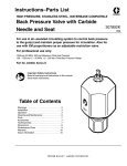
1
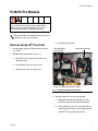
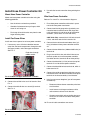
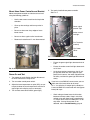
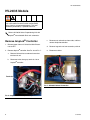
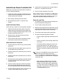
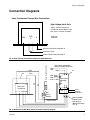
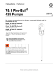
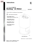
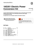
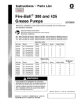
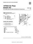
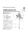
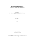
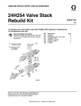
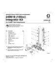
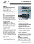
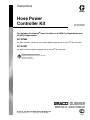
Instructions
Hose Power
Controller Kit
311510C
For replacing the AmpLok® Hose Controller on H-20/35 Pro Proportioners and
HV-20/35 Proportioners.
Kit 297983
For 230V and 380V H-20/35 Pro and HV-20/35 Models equipped with an AmpLok® Hose Controller.
Kit 261287
For 460V H-20/35 Pro Models equipped with an AmpLok® Hose Controller.
Important Safety Instructions
Read all warnings and instructions in manuals
311392 and 311393.
Save these instructions.
Graco Inc. P.O. Box 1441 Minneapolis, MN 55440-1441
Copyright 2006, Graco Inc. is registered to I.S. EN ISO 9001
Contents
H-20/35 Pro Models . . . . . . . . . . . . . . . . . . . . . . . . . 3
®
Remove AmpLok Controller . . . . . . . . . . . . . . . 3
Install Hose Power Controller Kit . . . . . . . . . . . . . 4
HV-20/35 Models . . . . . . . . . . . . . . . . . . . . . . . . . . . 6
Remove AmpLok® Controller . . . . . . . . . . . . . . . 6
Install Hose Power Controller Kit . . . . . . . . . . . . . 7
Troubleshooting . . . . . . . . . . . . . . . . . . . . . . . . . . . . 8
2
Parts . . . . . . . . . . . . . . . . . . . . . . . . . . . . . . . . . . . . . 8
Kit 297983 . . . . . . . . . . . . . . . . . . . . . . . . . . . . . . 8
Kit 261287 . . . . . . . . . . . . . . . . . . . . . . . . . . . . . . 8
Connection Diagrams . . . . . . . . . . . . . . . . . . . . . . . 9
Graco Standard Warranty . . . . . . . . . . . . . . . . . . . 10
Graco Information . . . . . . . . . . . . . . . . . . . . . . . . . 10
311510C
H-20/35 Pro Models
H-20/35 Pro Models
Installing this equipment requires access to parts that
may cause electrical shock or other serious bodily
injury if work is not performed properly. This work
should be performed by a qualified electrician.
Refer to H-20/35 Pro Proportioner Service manual
311393 for current unit schematics.
Remove AmpLok® Controller
1. Remove power from unit. Switch the Main Disconnect to OFF.
d. Save two of the screws.
Hose Secondary
Circuit Breaker
AmpLok® Controller
2. Remove AmpLok® controller, see FIG. 1.
a. Use 5/32 in. hex key wrench to remove four
retaining screws.
b.
Pull controller down for easier access.
c.
Remove wires from all six terminals.
Hose Transformer Secondary Cables
FIG. 1: H-20/35 Pro Before Conversion
3. Remove cables that are no longer needed.
a. Remove the #6 red cable from top of circuit
breaker that went to the AmpLok® controller.
b.
Disassemble large wire nuts and tape. Discard
the two #16 black cables that went to the left two
AmpLok® terminals. Discard wire nuts.
311510C
3
H-20/35 Pro Models
Install Hose Power Controller Kit
4. Use wire ties to route new wires along existing bundles.
Mount Hose Power Controller
Mount new hose power controller to bracket using the
following guidelines:
•
Use the #8 nuts and washers provided.
•
Controller fits between bent-up flanges, which
mount in unit facing out.
•
Fan hangs off end of bracket away from the two
larger mounting holes.
Wire Hose Power Controller
Refer to FIG. 8 and FIG. 9 for connection diagrams.
1. Place hose power controller and bracket in space
next to the hose power transformer.
2. Connect two black 8-gauge wires (previously connected to lower transformer wires with large wire
nuts) to terminals #2 and #3 on top of hose power
controller. (These wires are 1252 and 1332.)
380V Units Only: connect black 1252 wire to terminal #2, and white neutral wire to terminal #3.
Install Fan Power Wires
Install new wires to power fan on hose power controller.
1. If necessary, use a stiff wire to feed the two new
wires from the lower compartment, through the middle (large) conduit, and to the upper control box.
See FIG. 2.
Feed wires through
middle conduit
3. Connect the two #0 transformer bottom wires (primary) to bottom of hose power controller terminal
#5.
4. Connect the two #220 wires (#460 on 460V units) to
terminal #6.
5. Plug in the red 2161 wire and white N wire to two
terminal spades on fan of hose power controller.
Use either terminal; terminals do not have polarity.
6. Connect the blue 3501 (+5 Vdc) wire to the top left
terminal #7 on side of hose power controller.
7. Connect the blue 3502 wire to terminal #8, which is
below terminal #7.
FIG. 2: H-20/35 Pro Upper Control Box - Conduit
2. Connect the red 2161 wire to a 2161 terminal. See
FIG. 3.
3. Connect the white N wire to a neutral (N) terminal.
See FIG. 3.
8. Connect the red #6 gauge hose cable that was connected to terminal 4 on the old controller to the open
terminal on the hose secondary circuit breaker.
9. Install current sensor doughnut (part of hose power
controller kit).
•
Disconnect #0 transformer secondary wire from
circuit breaker.
•
Install sensor on #0 large transformer cable,
and reconnect cable to circuit breaker.
•
Connect sensor black wire and white wire to terminals #15 and #16 on left side of hose power
controller.
10. Ensure all cable connections are secure.
FIG. 3: H-20/35 Pro Upper Control Box - Wiring
4
311510C
H-20/35 Pro Models
Mount Hose Power Controller and Bracket
Mount hose power controller and bracket to back wall
using the following guidelines:
5. Test newly installed hose power controller.
See FIG. 5.
1
•
Use the two screws saved from the AmpLok®
controller.
•
Clean up wire routings and tie wrap wires in
place.
•
Do not run wires over sharp edges of transformer frame.
•
Do not run wires against coil of transformer.
•
Reconnect heated hose if it was disconnected.
2
3
#7
#8
Green “signal
present” light
Amber current
limit light
#15
#16
4
5
6
Fan Terminals
(behind)
Fan Power
Wires
FIG. 5: H-20/35 Pro Hose Power Controller
•
Ensure the green signal light above terminal #4
is on.
•
Ensure the amber current limit light above terminal #5 is on.
•
As the hose reaches temperature, the O1 output light will flicker less until it goes out completely. As this occurs, the amber light will flicker
off slowly, and then the green light will flicker off
slowly.
FIG. 4: Completed Installation - H-20/35 Pro
Power On and Test
1. Turn power on to unit. Switch the Main Disconnect
to ON and switch the E-Stop to ON.
2. Turn on amber control power switch.
If you have a true RMS AC current meter, you can
check one of the hose cables for 45 amps
AC +/- 2a. while the O1 output light is steadily on.
A non-true RMS AC current meter will read approximately 30 amps.
3. Adjust the hose temperature set point (SP1) on control panel above the actual temperature until the O1
output light on the display stays on constantly.
4. Turn on hose zone control switch (green light).
•
311510C
Check voltage at lower hose circuit breaker
between two hose cables. Keep in mind that
voltage varies with hose length; approximately
11 Vac per 50 ft. of 3/8 in. bundle plus 1.5V for
whip hose. If correct hose power is not
detected, refer to Troubleshooting, page 8.
5
HV-20/35 Models
HV-20/35 Models
Installing this equipment requires access to parts that
may cause electrical shock or other serious bodily
injury if work is not performed properly. This work
should be performed by a qualified electrician.
Refer to HV-20/35 Series Proportioning Unit with
AmpLok® manual 63942-ID for unit schematics.
Remove AmpLok® Controller
c.
Remove nuts and washers from studs, and then
remove AmpLok® controller.
1. Remove power from unit. Switch the Main Disconnect to OFF.
d. Remove large wire nut from secondary cable 0.
2. Remove AmpLok® controller. See FIG. 6 and FIG. 7.
e. Disconnect cables.
a. Remove lid from blue transformer box on bottom-front of unit.
b.
Disconnect wires from gray terminals 1-6 on
AmpLok® controller.
Terminals
FIG. 7: HV-20/35 Before Conversion
FIG. 6: AmpLok® Controller (HV-20/35)
6
311510C
HV-20/35 Models
Install Hose Power Controller Kit
8. Connect blue 5 Vdc signal wires. Connect 3501 to
terminal #7, and 3502 to terminal #8.
Before you can install the new hose power controller kit,
it must be positioned properly.
9. Ensure all cable connections are secure.
1. Position hose power controller in bottom of box facing up. Ensure it is positioned for easy wire access
on top and left side of controller.
Mount Hose Power Controller and Bracket
Use screws and lockwashers provided in kit to secure
hose power controller to bottom of control box.
2. Mark through mounting feet for drill holes.
Power On and Test
3. Drill through #29 (0.136 in.). Tap 8-32 screw
threads.
Install Fan Power Wires
Install new wires to power fan on hose power controller.
1. Tape the two new wires (plain ends) to a piece of
flexible steel wire. Route wires from the lower compartment, through the middle (large) conduit, and to
the upper control box. See FIG. 2.
2. Route, tie wrap, and connect the wires to their
respective terminal blocks.
3. Plug in the wires with push-on connectors into the
fan terminals; terminals do not have polarity.
1. Turn power on to unit. Switch the Main Disconnect
to ON and switch the E-Stop to ON.
2. Turn on amber control power switch.
3. Adjust the hose temperature set point (SP1) on control panel above the actual temperature until the O1
output light on the display stays on constantly.
4. Turn on hose zone control switch (green light).
5. Test newly installed hose power controller.
•
Ensure the green signal light above terminal #4
is on.
•
Ensure the amber current limit light above terminal #5 is on.
•
As the hose reaches temperature, the O1 output light will flicker less until it goes out completely. As this occurs, the amber light will flicker
off slowly, and then the green light will flicker off
slowly.
Wire Hose Power Controller
1. Connect power wire 1252 from top of control box to
terminal #2.
2. Connect black wire 1332 (230V units) or wire N 10
ga.wht (380V units) to terminal #3.
3. Connect the two black transformer primary wires to
terminal #5.
If you have a true RMS AC current meter, you can
check one of the hose cables for 45 amps
AC +/- 2a. while the O1 output light is steadily on.
A non-true RMS AC current meter will read approximately 30 amps.
4. Connect the two white transformer primary wires to
terminal #6.
5. Route one of the large 6-gauge transformer secondary wires through the D Current Sensor, which is
included in the kit.
6. Connect the black 6-gauge transformer secondary
wires to each red 6-gauge hose power cable with
wire nuts supplied. Secure nuts with electrical tape.
•
Check voltage at lower hose circuit breaker
between two hose cables. Keep in mind that
voltage varies with hose length; approximately
11 Vac per 50 ft. of 3/8 in. bundle plus 1.5V for
whip hose. If correct power is not detected, refer
to Troubleshooting, page 8.
7. Connect D Sensor doughnut wires to terminals #15
and #16. Polarity does not have any affect.
311510C
7
Troubleshooting
Troubleshooting
Problem
No lights on hose power controller.
Cause
Solution
No 4.5 to 12 VDC signal from temperature controller
Make sure connection for 01 light on
temperature controller is good.
Polarity is reversed on 4.5 to 12 VDC. Reverse blue wires.
No power to hose power controller
terminals 2 and 3; 220-240 VAC or
460 VAC on 460V models.
Green light on, but amber light not
on.
Opening in hose circuit.
Make sure green light on hose switch
is on. Make sure circuit breaker is on.
Disconnect main hose plug. Check
for 0.4 - 6 Ω resistance. Make sure
all hose connections are secure.
Hose secondary circuit breaker open. Check breaker. Check for continuity
across breaker.
Hose power primary circuit breaker
blows.
Current sensor doughnut not connected.
Check hose power controller connections 15 and 16.
Hose cable not running through current sensor doughnut.
Check hose cable and reroute if
needed.
Hose power controller is set too high. Contact Graco Technical Assistance.
Parts
Kit 297983
Kit 261287
For 230V and 380V H-20/35 Pro and HV-20/35 Models
For 460V H-20/35 Pro Models
Part No.
120387
15H611
103229
157021
100284
15H646
117722
Part No.
120404
15H611
103229
157021
100284
15H646
8
Description
CONTROL, heater, 240V
BRACKET, mount, heater control
SCREW, cap, SCH
WASHER, lock, int
NUT, hex, MSCR
WIRE, pair, fan
NUT, wire
Qty.
1
1
4
4
4
1
2
Description
CONTROL, heater, 480V
BRACKET, mount, heater control
SCREW, cap, SCH
WASHER, lock, int
NUT, hex, MSCR
WIRE, pair, fan
Qty.
1
1
4
4
4
1
311510C
Connection Diagrams
Connection Diagrams
Hose Transformer Primary Wire Connections
High Voltage Units Only
(460V - connect two primary
transformer wires together to put
both coils in a series as shown)
220
0
220
Check for
Continuity
0
Black to Hose Power Controller 6
Wire Nut & Tape
Black to Hose Power Controller 5
Hose Heat Connector
FIG. 8: Hose Transfer Connection Diagram for 460V Machines
30
Hose Heat
Transformer
0
0
220 220
Blk
0
Blk
120
1333
1332
1252
Blk
37
7 12 3
8
Hose Power
4.5 to 12 VDC Controller
15
16
6 5
3501 Blue +
3502 Blue -
Red #6
Red #6
1253
From Upper Control Box
(Neutral on 380V Machines)
Fan
60A
Circuit
Breaker
Sensor Wires
2161
Neutral
(120 VAC)
230V and 380V
Machines only
See detail for
460 Volt machines
(FIG. 8)
FIG. 9: Watlow Din-A-Mite Hose Power Controller Hook-Up Diagram
311510C
9
Graco Standard Warranty
Graco warrants all equipment referenced in this document which is manufactured by Graco and bearing its name to be free from defects in
material and workmanship on the date of sale to the original purchaser for use. With the exception of any special, extended, or limited warranty
published by Graco, Graco will, for a period of twelve months from the date of sale, repair or replace any part of the equipment determined by
Graco to be defective. This warranty applies only when the equipment is installed, operated and maintained in accordance with Graco’s written
recommendations.
This warranty does not cover, and Graco shall not be liable for general wear and tear, or any malfunction, damage or wear caused by faulty
installation, misapplication, abrasion, corrosion, inadequate or improper maintenance, negligence, accident, tampering, or substitution of
non-Graco component parts. Nor shall Graco be liable for malfunction, damage or wear caused by the incompatibility of Graco equipment with
structures, accessories, equipment or materials not supplied by Graco, or the improper design, manufacture, installation, operation or
maintenance of structures, accessories, equipment or materials not supplied by Graco.
This warranty is conditioned upon the prepaid return of the equipment claimed to be defective to an authorized Graco distributor for verification of
the claimed defect. If the claimed defect is verified, Graco will repair or replace free of charge any defective parts. The equipment will be returned
to the original purchaser transportation prepaid. If inspection of the equipment does not disclose any defect in material or workmanship, repairs will
be made at a reasonable charge, which charges may include the costs of parts, labor, and transportation.
THIS WARRANTY IS EXCLUSIVE, AND IS IN LIEU OF ANY OTHER WARRANTIES, EXPRESS OR IMPLIED, INCLUDING BUT NOT LIMITED
TO WARRANTY OF MERCHANTABILITY OR WARRANTY OF FITNESS FOR A PARTICULAR PURPOSE.
Graco’s sole obligation and buyer’s sole remedy for any breach of warranty shall be as set forth above. The buyer agrees that no other remedy
(including, but not limited to, incidental or consequential damages for lost profits, lost sales, injury to person or property, or any other incidental or
consequential loss) shall be available. Any action for breach of warranty must be brought within two (2) years of the date of sale.
GRACO MAKES NO WARRANTY, AND DISCLAIMS ALL IMPLIED WARRANTIES OF MERCHANTABILITY AND FITNESS FOR A
PARTICULAR PURPOSE, IN CONNECTION WITH ACCESSORIES, EQUIPMENT, MATERIALS OR COMPONENTS SOLD BUT NOT
MANUFACTURED BY GRACO. These items sold, but not manufactured by Graco (such as electric motors, switches, hose, etc.), are subject to
the warranty, if any, of their manufacturer. Graco will provide purchaser with reasonable assistance in making any claim for breach of these
warranties.
In no event will Graco be liable for indirect, incidental, special or consequential damages resulting from Graco supplying equipment hereunder, or
the furnishing, performance, or use of any products or other goods sold hereto, whether due to a breach of contract, breach of warranty, the
negligence of Graco, or otherwise.
FOR GRACO CANADA CUSTOMERS
The Parties acknowledge that they have required that the present document, as well as all documents, notices and legal proceedings entered into,
given or instituted pursuant hereto or relating directly or indirectly hereto, be drawn up in English. Les parties reconnaissent avoir convenu que la
rédaction du présente document sera en Anglais, ainsi que tous documents, avis et procédures judiciaires exécutés, donnés ou intentés, à la suite
de ou en rapport, directement ou indirectement, avec les procédures concernées.
Graco Information
TO PLACE AN ORDER, contact your Graco distributor or call to identify the nearest distributor.
Phone: 612-623-6921 or Toll Free: 1-800-328-0211 Fax: 612-378-3505
All written and visual data contained in this document reflects the latest product information available at the time of publication.
Graco reserves the right to make changes at any time without notice.
MM 311510C This manual contains English.
Graco Headquarters: Minneapolis
International Offices: Belgium, China, Japan, Korea
GRACO INC. P.O. BOX 1441 MINNEAPOLIS, MN 55440-1441
www.graco.com
311510C
Rev. 1/2008