1
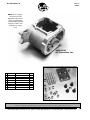
REV C
09/02
No.8028C6-IS
Instruction for JIMS® 4/6-speed Pro cut /Clean cut transmissions , Super Kits, & 4/5 case
Instruction sheets for part numbers 8028C6, 8030C6, 8101, 8028P6, 8030P6 & 8101P, 8096, 8096P
WARNING: Read all instruction before performing work!
Application Requirements
1.
2.
3.
4.
5.
All 4/6-Speed transmissions come
with close ratio 1st gear, JIMS® billet pillow blocks, JIMS® chrome
top and side covers, chrome hardware and JIMS® 7075T billet chrome
trapdoors.
6.
JIMS 6-SPEED IN A 4-SPEED STYLE CASE
Clean-Cut 4/6 Speed
Application/ Year
FX & FL 1970 early ‘84
FX & FL 1970 early ‘84
FX & FL 1970 early ‘84
Part No. Case
8028C6
8030C6
8101
Plain Aluminum
Polished Aluminum
Super kit (No Case)
FX & FL 1970 early ‘84
FX & FL 1970 early ‘84
FX & FL 1970 early ‘84
Part No. Case
8028P6
8030P6
8101P
Plain Aluminum
Polished Aluminum
Super kit (No Case)
4/5 Speed Transmission Case
Application/ Year
FX & FL 1970 early ‘84
FX & FL 1970 early ‘84
Part No. Case
8096
8096P
JIMS® 4/6-speed transmission will deliver increased gas mileage,
prolonged engine life, smoother shifting, increased torque, freed
horsepower, and smoother cruising speeds while still using a 4speed style case.
JIMS® 4/6-speed transmissions are assembled by JIMS® with JIMS®
shafts and gears incased in a JIMS® case. All JIMS® transmissions are
sealed with JIMS® gaskets and seals.
Pro-Cut 4/6 Speed
Application/ Year
For use on FX & FL style frames, 1970 - Early 1984 only
Dry clutch as used on 4-speed tapered I.D. clutch hubs.
Chain final drive (Transmission to rear wheel)
5-Speed style clutch cable
Electric start only (No provisions for kickers)
Designed to use OEM style forward controls and mid controls
available through aftermarket.
May be used with either primary belt or primary chain drive
Plain Aluminum
Polished Aluminum
Required (but not included) components for
complete transmissions & Super kit
37088-79
38607-87A
45031-65
2226
74420-94*
Aftermarket*
Aftermarket*
12018
37090-79
35126-36
72405-98BK
72405-98TN
35211-36
37089-79
33715-85AC
33336-83*
Center clutch pushrod (H.D.®)
Clutch cable (H.D.®)
Clutch cable pivot pin (H.D.®)
Clutch release bearing kit (JIMS®)
Electronic Speedo Sensor
Speedo with built in calibrator
Forward controls (H.D.®) or equivalent)
Inner Primary Seal (H-D®)
Left clutch pushrod (H.D®)
Lock washer, MDG (JIMS®)
Neutral switch connector (H.D.®)
Neutral switch connector (H.D.®)
Nut, main drive gear (H.D.®)
Right clutch pushrod (H.D.®)
Shifter lever (JIMS®)
Sprocket 23T or larger (Aftermarket)
9037
Primary Bearing (H.D.®)
*Optional, may be used with aftermarket equivalent
JIMS® Clean-Cut gears feature back cut shift dogs with lead-in ramping on mating gears for smooth shifting. Each gear in this kit (Close
ratio first gear, 2.94) is precision machined from forged aerospace
material and is matched to their corresponding gear.
JIMS® Pro-Cut gears provide smoother more positive shifting with
their precision machined and matched mating gears. Each Pro-Cut
Gear utilizes a steeper back cut shift dog angle than Clean Cut gears
for quicker engagement during high speed acceleration. All gears are
American made by JIMS® under stringent tolerances.
Note: See page 3 for important case information
Additional required (but not included) components for Super
kits 8101 & 8101P only
8978*
8996*
2371CK*
Bearing, Main drive case (JIMS®)
Bearing, Main drive case (JIMS®)
Clutch release cover, clutch mechanism and
hardware (JIMS®)
36801-87K*
Gasket, Side cover (10pk) (JIMS®)
33902-98*
Neutral switch (JIMS®)
11057K
Retaining ring,(10pk) (JIMS®)
11161*
Retaining ring (10pk) (JIMS®)
12067A*
Seal, Main drive case (JIMS®)
805*
Seal, Main drive case (JIMS®)
33119-79A*
Shifter arm adjuster screw (10 pk JIMS®)
7515K*
Shifter arm adjuster nut (JIMS®)
2384*
Shifter pawl assembly (JIMS®)
8089*
Spacer, Main drive (JIMS®)
33334-79*
Spacer, Main drive (JIMS®)
8999CK*
Top cover & fasteners (JIMS®)
8096,8096P*
Transmission Housing (JIMS®)
11165*
Quad seal (JIMS®)
*Optional, may be used with aftermarket equivalent
“From the Track... To the Street!”
555 Dawson Drive, Camarillo, CA 93012 • Phone 805-482-6913 • Fax 805-482-7422 • www.jimsusa.com
1
REV C
09/02
No.8028C6-IS
TRANSMISSION INSTALLATION INSTRUCTIONS
WARNING: ALWAYS REMOVE NEGATIVE CABLE FROM BATTERY BEFORE PERFORMING ANY WORK!
Pre-installation procedures (Complete Transmission Assembly)
Read all Instructions before performing any work
1. Unpack and inspect all parts for damage, or missing components. Immediately notify the JIMS® dealer you
purchased this transmission from for appropriate actions. Use the parts list on page 12-13 of these instruction sheets for inventory reference. Use JIMS® tool No.1008-TL trans holder for performing pre-installation
work.
2. Remove original transmission according to your Harley-Davidson® Service manual.
3. Clean and inspect all reusable parts and components, and replace parts as needed.
4. Check all parts for correct fitment before installing transmission.
5. Remove the side cover (No.2371C) from trans assembly. Lube and install three clutch pushrods
(H.D.®37089-79 right, H.D.® No 37088-79 center, and HD.® No.37090-79 left) inside main shaft, also attach
clutch release bearing kit (JIMS® No2226) to right pushrod (No.37089-79). Attach clutch cable o-ring
(No.11179) and clutch cable to side cover (No.2371C). Also connect end of clutch cable-to-cable coupler
(No.34920-86) and attach to inner ramp inside side cover. Now you are ready to mount gasket
(No.36801-87A) and side cover (No.2371C) to trans assembly. Lube and torque side cover screws to 10-12
ft-lbs.
6. (Optional) Install JIMS® No.74420-94 electronic speedo sensor into the trap door speedo hole. NOTE: Early
transmissions used a mechanical drive from the trans case to drive the speedo, while later 4-speed transmissions
used a mechanical drive from the front wheel . JIMS® new 4/6-speed was designed to be used with JIMS®
No.74420-94 electronic speedo sensor in conjunction with one of the many aftermarket electronic speedos (with
a built in calibrator).
7. (Optional) If you decide not to use JIMS® electronic speedo sensor you must install JIMS® No.8042 speedo
sensor hole block-off plate (included in kit with gasket and screw), or aftermarket equivalent.
Step- 1 Mount Transmission
With primary covers removed, align transmission-mounting studs with transmission plate mounting holes
and anchor the transmission to the transmission mounting plate with nuts and washers. Tighten nuts
enough to lock transmission in place. Do not tighten to proper torque. CAUTION: Protect mounting stud
threads while mounting. All JIMS® transmissions are shipped with a main shaft spline protector, this protector
should be left in place until transmission is fully mounted and secured.
Step- 2 Install main drive gear final drive sprocket
1. Place final drive sprocket No.33336-83 (H.D.® ref.) on main drive gear with convex side of sprocket (Note:
must use 23 tooth or larger) facing outward with lock washer H.D.® No.35126-36 and nut H.D.® No. 3521136.
2. Lock sprocket with chain and JIMS® tool no.2234, and tighten sprocket nut to 110-120 ft-lbs. of torque.
Bend one tab on lock washer.
3. Install shifter arm, JIMS® No. 33715-85AC on to shifter spline shaft. Tighten shifter arm bolt to 18-22 ft-lbs
of torque. NOTE: JIMS® suggest positioning the shifter arm slightly off center pointing up and forward. (11:55
on a clock)
Step- 3 Assemble inner primary cover to engine/transmission
1. Replace old inner primary bearing and seal. Install new bearing (H.D.® No.9037) and (H-D® No.12018) seal.
NOTE: You must support the inner primary bearing bore as you install the new bearContinued on page 3 -->
CAUTION:
Wear safety glasses. Excessive force may damage parts! ,See JIMS® catalog for over 100
other top quality professional tools. The last tools you will ever need to buy.
“From the Track... To the Street!”
555 Dawson Drive, Camarillo, CA 93012 • Phone 805-482-6913 • Fax 805-482-7422 • www.jimsusa.com
2
REV C
09/02
No.8028C6-IS
ing and seal.
2. Loosen transmission-mounting nuts. NOTE: There must be enough play to position transmission, inner primary
cover, and frame to prevent any binding.
3. Align inner primary cover with transmission mounting studs and secure it with anchoring nuts and bolts to
H.D.® factory specs per H.D.® manual.
4. Before continuing, check the clearance between inner primary cover, and the final drive sprocket with the
chain on, it should be with 0.05" – 0.06". NOTE: Some chains require more room and you may need to make
clearance. Also check nut no.35211-36 to seal No.12018 for having at least .050” of clearance
5. Tighten transmission to transmission mount plate. Torque to factory H.D.® manual specs. NOTE: Check
No.8049 mounting stud, shim if needed to sit level on frame. (Shim between frame and 5th mount)
6. Pre-assemble clutch hub and mount on main shaft. Check for clearance between clutch hub and inner primary cover, and relieve as necessary to maintain a clearance of .020” to .050”. Finish up assembly of clutch,
primary chain, adjuster, etc. per H.D.® service manual.
7. Attach clutch cable to handle lever assembly using H.D.® No.45031-65 clutch cable pivot pin. Clutch cable
length may vary per risers or handlebars. Check clutch adjustment per H.D.® manual for 1987 and later BT
5-speed models.
8. Use H.D.® No.72405-98TN and No.72405-98BK connector and wiring for connecting neutral switch wiring
to top of trans.
9. For ease of installation and cost use front wheel drive units to drive Speedo or see your dealer for electronic
Speedos and calibration units. Some fabrication will be required.
10. IMPORTANT! Add approximately 20-24 oz. Of 80W-90 transmissions gear oil, Jims No. 1230, to transmission through filler hole. After running transmission, allow bike to sit for a few minutes, and double check oil
level. Fill as needed. Change trans oil after 1st 500 miles of use and then change oil at normal H.D service
intervals.
Super Kit Pre-installation procedures
We have included the following instructions for the installing JIMS® No.8101 and No.8101P Super kits into
JIMS® No.8096, or 8096P transmission case. If using another manufactures case, please read super kit note
below. These instructions also apply to the disassembly and reassembly of JIMS® No.8028C6, 8028P6,
8030C6 and 8030P6 complete transmissions.
SUPER KIT NOTE
JIMS® TRANSMISSION CASE NOTE
Depending on the manufacturer of the case you are
using, you will need to measure the diameter of the
hole where the main drive gear bearing sits in the
case. If you have a dimension of approximately
2.95" diameter then you will need to use the following in the main drive gear area.
No.8096 & 8096P Pre-Assembly Procedures
5-Speed transmission installation
Note: Some assembly required (See pages 13-16).
If you are building a 5-speed transmission using
JIMS® 5-speed superkits No.8100 or No.8100P, or
an aftermarket equivalent you will not need to
modify this case. However, you should always check
for running clearances when mixing products from
other manufactures. Refer to the super kit note to
the left for main drive gear differences. Refer to
pages 13-16 for the listing of all parts associated
with the 8096/8096P transmission case kit.
6-Speed Transmission Installation
If you are installing JIMS® 6-speed Super Kits
No.8101 or 8101P you will need to read and follow
the entire instruction sheet No.8028C6. Please
note that JIMS® 6-speed super kits No.8101 and
No.8101P require case modifications for proper
case to gear clearances.
A. 2.95” Main drive gear case bearing
8978- bearing, Main drive case (JIMS®)
11057K- Retaining ring, (10pk) (JIMS®)
805- Seal, Main drive case (JIMS®)
33334-79- Spacer, Main drive (JIMS®)
B. 3.345” Main drive gear bearing (8096 &
8096P Kits)
8996- Bearing, Main drive case (JIMS®)
11161- Retaining ring (JIMS®)
8089- Spacer, Main drive (JIMS®)
11165- Quad seal (JIMS®)
12067A- Seal, Main drive case (JIMS®)
CAUTION:
Wear safety glasses. Excessive force may damage parts! ,See JIMS® catalog for over 100
other top quality professional tools. The last tools you will ever need to buy.
“From the Track... To the Street!”
555 Dawson Drive, Camarillo, CA 93012 • Phone 805-482-6913 • Fax 805-482-7422 • www.jimsusa.com
3
REV C
09/02
No.8028C6-IS
JIMS SPECIAL TOOLS
®
#2234
#94660-37A
#2260
#35316-80
#2189
#2362
#1078
Primary Drive Locking Tool
Main shaft Sprocket Wrench
Big Twin Sprocket Locker
5-speed Transmission Main Drive
5-Speed Shaft Installer
Lock ring pliers
Door Bearing Remover / Installer
Note: these modifications will not limit your ability to use a 4/5-speed gear set in the future.
CAUTION: Before grinding or filing (cover or
remove all bearings and seals, and any motor
or transmission parts in the area.)
Check No.1 - Main shaft 6th gear clearance
check (Note: You must maintain a .060” of gear
to case clearance at all times)
Placed the side door gasket provided
onto the dowel pins of the case. Figures 2-5
shows the areas of concern that has to be
checked.
WARNING
(NOTE: Read all instructions before performing work)
Prior to installation of this kit, please read and follow
the procedures and safety precautions to reduce the
risk of personal injury. Refer to your bike’s year and
model H.D.® Service Manual during installation of
this kit. Read these instructions completely so you
understand before performing any steps. Always disconnect battery cables to prevent injury. Your work
place should be clean and well lit. Wear safety glasses and protective clothing when working around
power tools and compressed air. Be careful with
chemicals when cleaning parts. Protect your skin
from solvents and use only in a well ventilated area.
Degreasers are flammable and are a fire hazard. Just
use common sense and exercise good judgment.
If the material of the case around the
5/16 -18 screw hole is above the profile of the
gasket, the material must be removed from the
case.
To accomplish this, mark the area with a
black felt pen and draw around the gasket as
shown in figure 3. Remove the marked material 1/2” inward (perpendicular to gasket surface)
from the gasket surface of the case. A die grinder
FIGURE NO.2
This kit is basically easy to install, but does require
some special tools (See tool list).
Use a 5-speed Big Twin H.D.® Service Manual and
parts book for reference. If you are not sure about
the procedures in these instructions, have a reputable H-D® repair shop perform those procedures
for you.
INSTALLATION INSTRUCTIONS
gasket
Case Preparation / Gear set Removal
FIGURE NO.3
If Super kit is replacing or refreshing an existing
4/5-speed, refer to your early 5-speed H.D.®
Service Manual for removal of your 5-speed gear
set.
The JIMS® 4/6-speed Super kit is designed
to fit into JIMS® and other 4/5-speed transmission
cases with some modifications. These modifications require that you remove case material in
key clearance areas. Please read all instructions
completely before attempting modifications.
CAUTION:
Wear safety glasses. Excessive force may damage parts! ,See JIMS® catalog for over 100
other top quality professional tools. The last tools you will ever need to buy.
“From the Track... To the Street!”
555 Dawson Drive, Camarillo, CA 93012 • Phone 805-482-6913 • Fax 805-482-7422 • www.jimsusa.com
4
REV C
09/02
No.8028C6-IS
must maintain a .060” of gear to case clearance at
all times) Remove approximately a .625” radius
perpendicular to the trap door.
FIGURE NO.4
See figure 5 and 6.
FIGURE NO.6
with a carbide burr tool for aluminum cutting can
be used or a course flat file also works well.
Check No.2 - Auxiliary fork shaft
bridge clearance
The auxiliary fork shaft bridge comes
installed on the inside of the side door as shown
in figure 4. The fork shaft bridge functions as the
support for the 4th C/S gear fork shaft.
Again, with the gasket still in place on the
dowels, notice the upper right hand corner of the
gasket, and if any aluminum is present below the
gasket, as shown in figures 2&3, remove the
material inward (perpendicular to gasket surface)
1-3/8” from the gasket surface. A large, coarse
round file works well.
Clearancing must also be done internally
on the right rear mounting stud perch. (Note: This
is for the third gear counter shaft clearance. You
FIGURE NO.5
Note: The stud hole will become partially exposed
while clearancing the above area. Some contact with
the steel stud may occur and it is important that you
use a die grinder bit suitable for both aluminum and
steel. All base studs have been coated with locking
compound prier to installation to prevent oil bypassing through this expose stud hole.
Check No.3 - Right side pillow block clearance
The right side pillow block/roller detent
assembly needs to be checked for proper fit to the
case. The face of the pillow block to case clearance
- see figure 7. Minimum clearance .010, maximum clearance is .060.
The pillow block / detent assembly must
also fit squarely down over the dowels.
Also check to make sure that some gap
FIGURE NO.7
CAUTION:
Wear safety glasses. Excessive force may damage parts! ,See JIMS® catalog for over 100
other top quality professional tools. The last tools you will ever need to buy.
“From the Track... To the Street!”
555 Dawson Drive, Camarillo, CA 93012 • Phone 805-482-6913 • Fax 805-482-7422 • www.jimsusa.com
5
REV C
09/02
No.8028C6-IS
FIGURE NO.8
NOTE: (See figure 1 for reference)
The JIMS® 6-speed Overdrive has only two
adjustments, just like the 5-speed. The first adjustment required is the shift drum end play which is
different than the 5-speed. The second adjustment is the shifter pawl adjusting screw which is
identical to early 5-speed and is performed as one
of the last steps in the installation.
exists (approximately. 1/16” - 1/8”) between the
torsion spring and the side of the case as shown in
figure 8.
Check #4 - Primary fork rod boss clearance
The boss, in which the fork rod slides
through, must be checked for clearance for the
main shaft 6th gear. Once again, use the side door
gasket for this check. Figure 2 & 9 shows the area
of concern. If the material of the case is outside
the profile of the gasket, remove material below
gaskets, 1/2” inward (perpendicular to gasket surface.) A large, coarse flat file works best
CAUTION: REMOVE ALL METAL FILINGS FROM
INSIDE OF CASE BEFORE FINAL ASSEMBLY.
ADJUSTMENTS / SET-UP AND CHECKS
In the 5-speed design, axial thrust from
the shift drum (during shifting) is controlled by
the right side pillow block only. Both pillow blocks
(left and right side) control the axial thrust on the
6-speed Overdrive. The shim to properly set-up
the end play is placed adjacent to the left side pillow block,
see figure 10.
Two shims are provided (a .030” and a
.025” shim) to set-up this clearance - end play
spec is .005” + / - .003.
Start by putting the .025 thick shim on
the end of the shift drum. Install the shift drum.
The kit includes (4) Allen Head bolts to hold the
pillow blocks in place, 3 of the bolts are 1/4”20”x1 1/4” socket head Allen, and one bolt is a
1/4”-20”x1 1/4” button head Allen.
Also, there are 3 A-N type washers, these
are used on the socket head Allen. The button
head bolt does not use a washer. The button
head bolt is used on the right side pillow block in
FIGURE NO.10
FIGURE NO.9
CAUTION:
Wear safety glasses. Excessive force may damage parts! ,See JIMS® catalog for over 100
other top quality professional tools. The last tools you will ever need to buy.
“From the Track... To the Street!”
555 Dawson Drive, Camarillo, CA 93012 • Phone 805-482-6913 • Fax 805-482-7422 • www.jimsusa.com
6
REV C
09/02
No.8028C6-IS
If the measured value is within spec., discard the
other shim and remove the shift drum / pillow
block assembly. If it is greater than .008”, repeat
procedure with the other (thicker) shim. In the
unlikely event it is less than the lower limit of .002
this is due to a variation in your housing, tolerance
stack-up of the JIMS® hardware, or a combination
of both.
FIGURE NO.11
the forward position, below the detent roller. See
Figure 11.
Apply a small amount of assembly lube to
dowels. Put the Allen bolts into the pillow block
holes and tighten down the shift drum / pillow
block assembly squarely. ‘Squarely’ means tighten down the bolt, one turn each at a time to pull
down the pillow blocks over the dowels*. A circular pattern for tightening the four bolts works
best.
*The right side pillow block may be stubborn
in making its way over the dowels. Tightening down
the pillow block bolts in a circular pattern, as specified above, is usually sufficient to overcome this.
Measure the end play next to the right
side pillow block as seen in figure 12.
FIGURE NO.12
Regardless of the cause, it needs to be corrected. Please call JIMS® and have some vernier
calipers available to take measurements during
your conversation to assist with diagnosis. If we
determine that the difficulty is with your case, we
will advise you how to remedy the situation. If the
difficulty is with our hardware, we will ship
replacement hardware to remedy the situation.
With the preceding checks and set-ups
out of the way, you are now ready to begin installation.
GEAR SET INSTALLATION FOR CLEAN CUT
& PRO CUT GEARS 6-SPEEDS
Note: Apply assembly lube to all moving parts, from
your seals to your bearings.
(Note: Some aftermarket 4/5 transmissions cases
may use other year main drive gear bearings. See
page 3 Super Kit note.) NEVER install the bearing
into the case by applying pressure to the inner
race, you will destroy the bearing. Install the new
retaining ring, JIMS® No.11067K with the bevel
facing out. For a new case, install the main drive
gear bearing with assembly lube and retaining
ring as indicated. Install the main drive gear into
the main drive gear bearing using the same
JIMS® tool No.35316-80. Hang the side door gasket onto the case dowel pins and carefully push
it down to seat against the case gasket surface.
Apply some spray lube JIMS® No.1226 or
equivalent to the main drive gear seal and to the
main shaft (on the portion adjacent to the
splines).
CAUTION: MAKE SURE THE SEAL PROTECTOR
IS STILL ON THE END OF THE MAIN SHAFT,
BEFORE SLIDING THROUGH THE MAIN DRIVE
GEAR.
(see figure 1)
Install the gear set by sliding the main
CAUTION:
Wear safety glasses. Excessive force may damage parts! ,See JIMS® catalog for over 100
other top quality professional tools. The last tools you will ever need to buy.
“From the Track... To the Street!”
555 Dawson Drive, Camarillo, CA 93012 • Phone 805-482-6913 • Fax 805-482-7422 • www.jimsusa.com
7
REV C
09/02
No.8028C6-IS
shaft through the main drive gear and slowly
pushing the whole trap door / gear set assembly
until the case dowel pins contact the dowel holes
in the side door. A rubber hammer is helpful to tap
the side door over the case dowel pins without
risking any damage to the aluminum / chrome of
the side door.
Install the four 5/16” SHCS (socket head
cap screws, with lube on the threads) in the lower
4 screw holes and torque them to 13-16 ft-lbs.
Install the two 1/4” SHCS in the screw holes above
each dowel and torque them to 7-9 ft-lbs.
small amount of lube No.1226 on small end of
shaft only, through trap door and into shift fork
No. 8069A C/S 4th fork.
NOTE: While pushing the auxiliary fork shaft
through, hold onto the 4th C/S gear fork and make
sure the fork is positioned correctly to receive the auxiliary fork shaft that is simultaneously being pushed
through.
Install set screw No.3784C with 2 drops of
Thread locking compound No. 242 on screw and
in threaded hole. To hold shaft No.8075 in place.
Torque to 2-4 Ft Lbs.
Shift Fork Installation
Function check
Figure 1 details the names of the 4 shift
forks that are provided with this kit. Page 11
details where these forks belong on the gear set.
The 3rd C/S, 2nd M/S, and 1st M/S forks will ride
on the primary fork rod (like 5-speed). The 4th
With the 4 forks and the primary and secondary fork rods installed, check to make sure that
the forks slide freely on the fork rods by moving
them back and forth with your fingers. In particular, if you experience any binding of the 4th C/S
fork, you most likely need to go back and perform
clearance check #2 in the case clearance checks
section.
FIGURE NO.13
SHIFT DRUM / DETENT SYSTEM /
PILLOW BLOCK INSTALLATION
C/S fork rides on the auxiliary shaft that will be
pushed through the door.
First, install the 1st M/S fork. You must
slide the 1st gear away from the door and engage
the dogs of the adjacent gear (4th) to allow room
for the fork to slide, see Figure 13.
Next, install the 4th C/S fork.
Clutch Rod End - Right Side
Refer to the Pre-installation procedures on
page 2.
CLUTCH RELEASE COVER INSTALLATION
Install the 3rd C/S and 2nd M/S forks in
the positions specified. Slide the primary fork rod
through the 1st M/S fork, 3rd C/S fork, and 2nd
M/S fork.
Insert shift fork shaft No. 8075, with a
CAUTION:
Install the shift drum assembly as detailed
in the Adjustments / Set-Up and Checks section.
This time, however, you must be careful to make
sure the fork pins are in the grooves in which they
belong. As mentioned before, it is recommended
that you tighten down the Allen bolts in a circular
pattern. Monitor closely the pins of the forks relative to the shift drum grooves. Application of
Thread locking compound No. 242 to all four
bolts is recommended. Set the adjustment on the
shifter pawl adjustment screw per H.D.® Service
Manual Section 7, SHIFTER LINKAGE Adjustment.
Install clutch release cover onto the side
door. Note: that two of the screw holes in the side
door that receive two clutch cover screws have a
threaded depth of 1/2”. This means, if you are
using and O.E.M. style clutch cover, you must use
Wear safety glasses. Excessive force may damage parts! ,See JIMS® catalog for over 100
other top quality professional tools. The last tools you will ever need to buy.
“From the Track... To the Street!”
555 Dawson Drive, Camarillo, CA 93012 • Phone 805-482-6913 • Fax 805-482-7422 • www.jimsusa.com
8
REV C
09/02
No.8028C6-IS
the two 1/4-20x2” SHCS that are provided, or any other SHCS with a 2” length. The positions of these two screw
holes are shown in figure 15. If you are installing a JIMS® billet cover the correct length screws are supplied with
the cover kit. If you are using any other custom cover, check and make sure the screws do not bottom out in the
side door holes.
SPEED SENSOR INSTALLATION
If you have a transmission case with speed sensor provisions, install one of the sensor block-off plate kits
No. 8042K in the case. Relocate the speed sensor to the provision in the side door. If you are not running a speed
sensor, use another block off plate kit No. 8042K, in the side door. You may require a speed sensor signal conversion box to correctly calibrate the speedo head. Dakota Digital speed recalibration units (model SGI - 6) are available through: Dakota Digital, 3421 W. Hovland Ave., Sioux Falls, SD 57107 Phone: (605) 332-6513 Fax: (605) 339-4106
Fluid Fill
Fill the assembled gearbox with 20-24 oz. of Torco 80W-90W oil, JIMS® No. 1230. Change oil at 500 miles.
Refill case with Torco 75W-140 Synthetic, JIMS® No.1232
DISASSEMBLY
In general, disassembly of your JIMS 6-speed Overdrive is the reverse of content of the Installation Instructions
with only one note; to remove the auxiliary fork shaft No.8075, you may need a slide hammer with a 10-32 threaded tip.
®
WARRANTY
All JIMS® parts are guaranteed to the original purchaser to be free of manufacturing defects in material and workmanship for a period of six (6) months from the date of purchase. Merchandise that fails to conform to these conditions will be
repaired or replaced at JIMS® option if the parts are returned to us by the purchaser within the six (6) months warranty period
or within ten (10) days thereafter.
In the event warranty service is required, the original purchaser must call or write JIMS® immediately with the problem.
Some problems can be rectified by a telephone call and need no further course of action. A part suspected of being defective
must not be replaced by a dealer without prior authorization by JIMS®. If it is deemed necessary for JIMS® to make an evaluation to determine whether the part is defective, it must be packaged properly to prevent further damage and be returned prepaid to JIMS® with a copy of the original invoice of purchase and a detailed letter outlining the nature of the problem, how the
part was used and the circumstances at the time of failure. If after an evaluation has been made by JIMS® and the part was
found to be defective, repair, replacement or credit will be granted.
1.
2.
3.
4.
5.
CAUTION:
ADDITIONAL WARRANTY PROVISIONS
JIMS® shall have no obligation in the event a JIMS® part is modified by person or organization.
JIMS® shall have no obligation if a JIMS® part becomes defective in whole or in part as a result of improper installation, improper maintenance, improper use, abnormal operation, or any other misuse or mistreatment of the
part.
JIMS® shall not be liable for any consequential or incidental damages resulting in the failure of a JIMS® part, the
breach of any warranties, the failure to deliver, delay in delivery, delivery in non-conforming condition, or for
any other breach of contract or duty between JIMS® and a customer.
JIMS® parts are designed exclusively for use in Harley-Davidson® motorcycles. JIMS® shall have no warranty or liability obligation if
JIMS® part is used in any other application.
Any JIMS® parts or tools that are returned and replaced become the property of JIMS® and will not be returned under any circumstance.
Wear safety glasses. Excessive force may damage parts! ,See JIMS® catalog for over 100
other top quality professional tools. The last tools you will ever need to buy.
“From the Track... To the Street!”
555 Dawson Drive, Camarillo, CA 93012 • Phone 805-482-6913 • Fax 805-482-7422 • www.jimsusa.com
9
REV C
09/02
No.8028C6-IS
FIGURE NO.1
Super kit Assembly
SPEEDO BLOCK
OFF PLATE, GASKET, & SCREW
MAIN SHAFT SEAL
PROTECTOR
SHIFT DRUM
SHORT BOLTS
FOR TRANS SIDE
COVER
LEFT SIDE PILLOW BLOCK
EAR SET &
RAP DOOR
SSEMBLY
RIGHT SIDE PILLOW
BLOCK DETENT
ASSEMBLY
PILLOW
BLOCK
SCREWS
PILLOW
BLOCK
WASHERS
1ST M/S
GEAR FORK
SIDE DOOR
FASTENER
3RD GEAR
FORK
2ND M/S
GEAR FORK
CLUTCH RELEASE
BEARING KIT
Shift Fork
shaft
4TH C/S
GEAR
FORK
SET SCREW
(FORK SHAFT
4TH GEAR)
AUXILIARY
FORK SHAFT
(4TH GEAR
C/S
SHIMS (SHIFT DRUM)
(.025 AS NEEDED)
(.030 AS NEEDED)
COUNTER SHAFT
BEARING
10
REV C
09/02
No.8028C6-IS
Shifter Fork
Location
FIGURE NO.14
CAUTION:
Wear safety glasses. Excessive force may damage parts! ,See JIMS® catalog for over 100
other top quality professional tools. The last tools you will ever need to buy.
“From the Track... To the Street!”
555 Dawson Drive, Camarillo, CA 93012 • Phone 805-482-6913 • Fax 805-482-7422 • www.jimsusa.com
11
REV C
09/02
No.8028C6-IS
Trap Door Assembly
FIGURE NO.15
2” SHCS
Fastener
NO.
9
8
7
6
5
4
3
2
1
CAUTION:
QTY.
1
1
1
2
2
1
1
2
1
TITLE OR DESCRIPTION
SET SCREW, CHROME
SPLIT PIN
MAGNETIC DRAIN PLUG
SCREW, BUTTON HEAD
SCREW, BUTTON HEAD
BRIDGE SUPPORT
RETAINER PLATE
BEARING
4/5/6 CHROME BILLET TRAP DOOR
PART NO.
3784C
609
739A
8090
8091
8074
8073
8998
8095C
Wear safety glasses. Excessive force may damage parts! ,See JIMS® catalog for over 100
other top quality professional tools. The last tools you will ever need to buy.
“From the Track... To the Street!”
555 Dawson Drive, Camarillo, CA 93012 • Phone 805-482-6913 • Fax 805-482-7422 • www.jimsusa.com
12
REV C
09/02
No.8028C6-IS
FIGURE NO.16
Exploded View
Pro-Cut & Clean-Cut
114
116
115
CAUTION:
Pro-cut gears are designed and manufactured different than clean-cut gears. Clean -cut gears are not designed to work
with pro-cut gears. Do not mix gears. Each pro-cut gear is identified by 3 “pip” marks (dots see figure 18) on each gear.
6-speed pro-cut gears sets must be assembled on the proper shaft, with the dogs facing the correct mating gear. Gears
are lasered with part No.)
Note: Assemble pro-cut gears on the main shaft and counter shaft using assembly figure No.18. Check part number
before and after gears are assembled on shafts. This step is essential for proper assembly of the transmission. Improper
placement of the gears will result in the malfunction of the transmission and damage.
Customer Support: For any installation on service or Questions, please contact JIMS® technical Depart. @ 805-482-6913.
13
REV C
09/02
No.8028C6-IS
4/5/6-Speed transmission parts list.
Clean-cut and Pro-cut gears.
Parts List
No.
1
2
3
4
5
6
7
8
9
10
11
12
13
14
15
16
17
18
19
20
21
22
23
24
25
26
27
28
29
30
31
32
33
34
35
36
37
38
39
40
41
42
43
44
45
46
47
48
49
50
51
52
53
54
55
56
57
58
59
Qty.
1
1
1
1
1
2
1
1
1
1
1
5
1
1
7
8
1
1
1
1
2
1
1
1
1
1
1
1
1
4
2
1
1
2
1
1
1
1
3
2
1
1
1
1
1
1
1
1
1
1
4
4
4
1
2
6
1
1
1
Description
Trap door, 4-5-6 Speed w/speedo hole
Main Shaft, 4-5-6 Speed
Countershaft combo 5th gear, 4-5-6 Speed
Gear, 1st, Mainshaft Close ratio 6-Speed, Clean-Cut
Gear, 2nd, Mainshaft, Clean-Cut
Gear, 3rd, Mainshaft, 2nd Countershaft, Clean-Cut
Gear, 4th, Mainshaft, Clean-Cut
Gear, 5th, Mainshaft, Clean-Cut
Gear, 1st, Countershaft, Close Ratio
Gear, 4th, Countershaft, Clean-Cut
Gear, 5th, Countershaft, Clean-Cut
Bearing, Mainshaft & Countershaft
Bearing, Countershaft end
Bearing, Transmission Case
Thrust Washer, Mainshaft & Countershaft
Retaining Ring, Mainshaft & Countershaft
Retaining Ring, Main Drive Gear Bearing
Seal, Spacer
Gear, 3rd, Countershaft, Clean-Cut
Gear, 6th, Mainshaft, Clean-Cut
Locknut, Mainshaft & Countershaft
Thrust Washer, Mainshaft 6th Gear
Shift Drum, 6-Speed, Late
Throwout Bearing Kit
Pillow Block, Billet, Right Assembly, 6-Speed
Pillow Block, Billet, Left
Shift Fork, 1st Gear Mainshaft, 6-Speed
Shift Fork, 4th Gear, Countershaft, 6-Speed
Thrust Washer, Shift Drum, .025”
Screw, SHCS, Chrome, 5/16-18 x 1 1/4 (Door)
Screw, SHCS, Chrome, 1/4-20 x 1 1/4 (Door)
Rod, Shift Fork, 4th, 6-Speed
Screw, BHCS, 1/4-20 x 1 (Pillow Block)
Screw, SHCS, Chrome, 1/4-20 x 2 3/4 (End Cover)
Screw, SHCS, 1/4-20 x1 1/8
Box, With Foam Insert
Instructions Sheet
Seal, Main Drive Gear
Washer, AN 1/4” (Pillow Block)
Screw, SHC, 1/4-20 x 1 1/4 (Pillow Block)
Shift Fork, 2nd Gear, Mainshaft
Shaft, Shift Forks
Case, Polished, W/Pins & Studs, Machined
Lever Shaft
Seal, Shaft, Shifter Lever
Washer, Shifter Shaft
Lock Ring, Shifter Shaft
Screw, Adjuster
Nut, Adjuster Screw
Mount, Transmission
Screw, Flathead, Mount
Stud, Bottom, Mount
Stud, Primary, Mount
Plug, Magnetic, w/nylon washer
Screw, Set
Roll Pin
Cover, End, Chrome
Gasket, Door
Gasket, Lid
Part Number
8095C
8072
8094
8061
35026-79
35027-79
35028-79
35029-79
8062
8064
35626-79
8876A
8048
8996
6003
11067
11161
8089
8063
8065
35078-79
8081
8071-1L
2226
8079W
2528-1
8068A
8069A
8077-1
1118
1258
5075
1287
1260
1213
2393
8028C6-IS
12013A
1215
2135
34193-79E
34088-87
8096MP
34084-86A
12045
6497HW
11150
33119-79A
7515
8049
8054
8052
8053
60348-65B
3784C
609
2371C
35652-79
34904-86
14
No.8028C6-IS
4/5/6-Speed transmission parts list.
Clean-cut and Pro-cut gears.
60
61
62
63
64
65
66
67
68
69
70
71
72
73
74
75
76
77
78
79
80
81
82
83
84
85
86
87
88
89
90
91
92
93
94
95
96
97
98
99
100
101
102
103
104
105
106
107
108
109
110
111
112
113
114
115
116
1
1
1
1
2
3
4
3
1
1
1
1
1
1
1
1
3
1
1
1
1
1
1
1
1
1
1
1
2
1
2
1
2
1
1
1
1
1
2
1
1
1
1
1
1
1
1
1
1
1
1
1
1
1
1
1
1
Cover, Top Lid, Chrome
Seal, Main Drive, Gear
Screw, SHCS, 1/4-20 x 1 (Lid)
O-Ring, Clutch Cable
Screw, SHCS, 1/4-20 x 3/4 (Side Cover)
Oil, 1 Quart
Screw, SCHS, 1/4-20 x 3/4 (Lid)
Screw, SCHS, 1/4-20 x 1 1/2 (Lid & Side Cover)
Cap, Plastic
Switch, Neutral, late
Vent, Fitting
Retaining Ring, Ball Ramp
Ramp, Inner
Ramp, Outer
Gasket, End Cover
Coupler, Cable
Ball Bearing, Ramp
Dip Stick
Pin, Dowel
Pin, Roll
Bushing, Shifter Shaft
Quad Seal
Tubing, Shrink
Ring, Retaining
Washer
Pawl, Shifting Shaft
Plate, Shifter Shaft
Spring, Shifter Shaft
Bearing, Trapdoor
Plate, Retaining
Screw, BHSS 1/4-20 x 1/2
Support, Bridge
Screw, BHSS, 5/16-18 x 3/4
Bearing, Pillow Block, Left
Race, Inner
Spring, Detent
Plug, Magnetic Drain
Bearing, Shift Drum
Bearing, Main Drive Gear
Case, Plain, W/Pins & Studs, Machined
Case, Plain, Assembly
Case, Polished, Assembly
Shifter Lever Assembly
Left Pillow Block Assembly
Late Shift Drum Assembly
Right Pillow Block Assembly
Chrome Lid Assembly
Chrome Side Cover Assembly
Gear, 2nd, Mainshaft, Pro-Cut
Gear, 3rd, Mainshaft, Pro-Cut
Gear, 4th, Mainshaft, Pro-Cut
Gear, 1st, Mainshaft, Pro-Cut
Gear, 2nd, Countershaft, Pro-Cut
Gear, 3rd, Countershaft, Pro-Cut
Speedo Sensor Block-Off Plate
Gasket, Speedo Block-Off Plate
Screw, Speedo Block-Off Plate
REV C
09/02
8999C
12067A
1115
11179
1121
1230
1259
1261
2401
33902-98
62375-57
10998
25452-87A
25453-87A
36801-87A
34920-86
8873
37075-87
375
634
33114-79
11165
8012
11016
6016
35086-79
35068-79J
34087-79A
8998
8073
8090
8074
8091
9115
8082
8079-2
739A
35961-52
8904
8096M
8096
8096P
2384
2528
8071AL
8079A
8999PK
2371CH
8058-3
8058-5
8058-7
8061P
8058-2
8063P
8042
8041
1120
15
REV C
09/02
No.8028C6-IS
NOTE: Please see page 3
for transmission case
application requirements.
Please use appropriate
thread locking compounds
and press fit lubes when
installing these components.
8096/8096P
4/5 Transmission Case
50
#
53
50
54
79
78
56
51
Part no.
8053
8049
60348-65B
8096(P)
634
375
609
8054
Description
Stud, Primary cover
Bracket, Bottom
Drain Plug
Case
Roll Pin, F-door
Dowel Pin, R-door
Pin, Lid
Screws, Bracket
Qty.
4
1
1
1
1
1
4
4
53
79
78
51
56
54
CAUTION:
Wear safety glasses. Excessive force may damage parts! ,See JIMS® catalog for over 100
other top quality professional tools. The last tools you will ever need to buy.
“From the Track... To the Street!”
555 Dawson Drive, Camarillo, CA 93012 • Phone 805-482-6913 • Fax 805-482-7422 • www.jimsusa.com
16