1
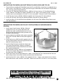
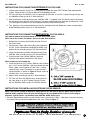
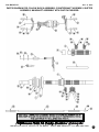
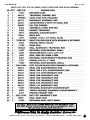
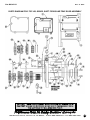
No.8236-IS
Rev C 8/07
A Division of Thiessen Products, INC
Instruction Sheet For JIMS® Right Side Drive 6-Speed Overdrive
JIMS® R.S.D. 6-Speed Overdrive complete
Transmission Kit numbers 8248, 8249, 8250, 8251,
8252, 8253, 8259, 8260, 8266 and 8267.
We have included this instruction sheet for reference to disassemble the transmission. Disassembly is the same as assembly, but in reverse order.
READ ALL INSTRUCTIONS BEFORE PERFORMING WORK!
Prior to installation of this kit, please read and follow the procedures and safety precautions to reduce the risk of personal injury.
IF YOU DO NOT KNOW WHAT YOU ARE DOING,
DO NOT DO IT!
No information in this instruction sheet pertaining to motorcycle repair is represented as fool proof or even altogether safe. Some people can ruin a mechanic’s vise with a tack hammer. Even something safe, done incorrectly
or incompletely can and will backfire. You are responsible for the safety of your work and knowledge of the tools,
repair equipment, components, methods and concepts needed to complete these tasks. You must carefully and
systematically perform each and every step safely. All information listed in this instruction sheet has been tested,
re-tested and used daily in JIMS® Research and Development Department.
JIMS® IS NOT RESPONSIBLE FOR THE QUALITY AND SAFETY OF YOUR WORK!
If you are not sure about any of the procedures in these instructions, have a reputable H.D. repair shop
perform these procedures for you.
WARNING: Always disconnect the Battery Ground Cable
(at the battery) to prevent injury. Your work area should
be well lit. Wear safety glasses (over your eyes) and protective clothing when working around power tools and
compressed air. Be careful with chemicals when cleaning
parts. Protect your skin from solvents and use only in a
well-ventilated area. Degreasers are flammable and are a
fire hazard. Just use common sense and exercise good
judgment. Securely mount the trans case (if not installed
in Motorcycle) with JIMS Tool No.1145 Complete Modular
Engine & Transmission Stand Kit or JIMS Tool No. 1289
Trans Stand. This kit is basically easy to install, but does
require some special tools. (See tool list)
NOTE: Any time you see ** It is an indication to lube using
JIMS No.1231 Transmission Oil for a lubricant.
(Example: Apply a small amount of Trans Lube **
to Parts being installed in this kit.)
Special Tools Required to install
JIMS R.S.D. 6 Speed Super Kit:
The only special tools required are tools that may
also be required for any 5-speed installation.
JIMS® Part No....Description:
35316-80 ......5-speed Main Drive Gear Tool
34902-84 ......Mainshaft Bearing Race Tool
94660-37A ...Mainshaft Sprocket Locknut Wrench
2260 .............Big Twin Sprocket Locker
1131 .............Small Lock Ring Pliers
1133 .............Large Lock Ring Pliers
1720 .............5-speed Main Bearing Remover
1102 .............Solvent 184
1080 .............Brass Hammer Continued Next Page
CAUTION: Wear safety glasses. Excessive force may damage parts!
See JIMS ® catalog for Hundreds of top quality professional tools.
The last tools you will ever need to buy.
555 Dawson Drive, Camarillo, CA 93012 Phone 805-482-6913 • Fax 805-482-7422
1
Rev C 8/07
No.8236-IS
Special Tools Required (Continued)
Special Parts Needed To install
JIMS® 6-Speed Super Kit:
JIMS® Part No....Description:
JIMS® Part No....Description:
1289 .............Trans Stand
1145 .............Modular Engine & Trans. Stand Kit
2256 .............Main Drive Gear Seal Protector
1664 .............Shift Lever Pivot Sleeve R & I
1231 .............Good Quality Gear Oil
8042K...........Speedo Block-Off Plate
(Depending on application)
42533-91A ...Vent Hose
Good Quality DOT 5 Brake Fluid
8126 .............Speedo-Recalibration Module
(Depending on pulley and tire size)
NOTE: Spacer No. 8424 is for Belt Pulley applications, if you will be using a Sprocket you need to shorten
or lengthen this spacer for proper Chain alignment to Rear Sprocket.
NOTE: To use Hydraulic Pulley Cover, JIMS No. 8422 you will need a Hydraulic Clutch Master Cylinder similar to H.D. No. 45232-03A, a Clutch Line (Braided Stainless Brake Line) that is about 70 inches long
(depending on Handle Bars, Risers and Frame) similar to H.D. No. 38669-03, except with a Banjo fitting at
each end, two Banjo Bolts like H.D. No 41747-82A and Sealing Washer (gasket) like H.D. No 41731-01.
NOTE: Refer to your Service Manual and parts book for the proper year and model you will be installing this
kit in for reference. Also, Use a Late H.D. 2002- Pres Big Twin Service Manual and parts book for reference.
INSTRUCTIONS FOR PREPARING THE TRANSMISSION CASE TO INSTALL JIMS R.S.D. 6
SPEED SUPER KIT: (COMPLETES HAVE BEEN PREPARED)
1.
Remove Old Gear set and all Case Bearings. Refer to your H.D. Service Manual.
NOTE: If Dowel Pin H.D. No. 634 came out upon the Gear Set removal, it will need to be reinstalled back
into the Trans Case. Refer to your H.D. Service Manual.
2.
Upgrade Shifter Shaft Bushing for 1990-99 Big Twins and 1999-2000 T/C FLHT, FXR & FXD by removing the
existing Shifter Shaft Bushing and installing a new longer shifter Shaft Bushing (Sleeve) JIMS No. 7514 (supplied in this kit). Follow the Instruction Sheet provided with JIMS Tool No. 1664 and refer to your Late H.D.
Service Manual for Shifter Shaft Assembly.
3.
Wash and rinse out the entire inside of your trans case.
4.
Install Main Drive Gear Bearing JIMS No. 8996 (supplied in this kit) using JIMS Tool No. 35316-80. Follow
the Instruction Sheet provided with Tool or Refer to your H.D. Service Manual.
5.
Install Retaining Ring JIMS No. 11161 (supplied in this kit). Refer to your H.D. Service Manual.
NOTE: NEVER install any bearings into the Case by applying pressure to the inner race. Doing so will
destroy the bearing.
6.
Install new Main Seal JIMS No. 12067 (supplied in this kit) with JIMS Tool No. 95660-85 used with JIMS Tool
No. 95660-42. Refer to you H.D. Service Manual.
7.
Install Countershaft End Bearing JIMS No. 8977. Refer to your H.D. Service Manual.
NOTE: Install Countershaft Bearing by applying pressure to the LETTER side of bearing ONLY.
8.
Install Shifter Shaft Seal JIMS No. 12045 (supplied in this kit). Refer to your H.D. Service Manual.
9.
Install Shifter Assembly JIMS No. 8325 (supplied in this kit). Refer to your Late H.D. Service Manual.
CAUTION: Wear safety glasses. Excessive force may damage parts!
See JIMS ® catalog for Hundreds of top quality professional tools.
The last tools you will ever need to buy.
555 Dawson Drive, Camarillo, CA 93012 Phone 805-482-6913 • Fax 805-482-7422
2
Rev C 8/07
No.8236-IS
10. Install Shifter Shaft Washer JIMS No. 6497HW and Retaining Ring JIMS No. 11150 (supplied in this kit).
Refer to your Late H.D. Service Manual.
11. Install Shifter Shaft Centering Pin (Bolt) JIMS No. 34978-00A (supplied in this kit). Torque Bolt to 10 ft-lbs.
Refer to your Late H.D. Service Manual.
Caution: Center shifter assembly return spring on each side of centering bolt.
INSTRUCTIONS FOR PREPARING THE TRANSMISSION TOP COVER TO CLEAR THE NEW
SHIFTING LEVER WHEN INSTALLING JIMS R.S.D. 6 SPEED SUPER KIT INTO ANY 1990-99
BIG TWINS AND 1999-2000 T/C FLHT, FXR & FXD MODELS:
9453
NOTE: The Top Cover for Completes have been
Prepared.
NOTE: 2000-Present FXST and 2001-Present FLHT &
FXD models do not need modifying.
1. Place new Top Cover Gasket JIMS No.34904-86 on the Trans
Top Cover flange.
2. Use 4 of your Top Cover screws to hold Gasket in place by
slipping screws thru the Gasket and into the Top Cover.
3. Mark the inside exposed portion of the flange as shown in
Figure 1. The Material to be removed is .060 wide by 1.80
Deep. Remove Top Cover screws and Gasket.
FIGURE 1
4. With a die grinder tool, remove the casting rib until it is the same height as the adjacent surface area. Clean
Top Cover of all loose material, including screw holes as shown in Figure 1.
5. With shifter assembly installed in transmission; Install Top Cover with gasket using only 2 screws loosely (so
cover can move if Shifter Arm is making contact with Top Cover).
6. While watching to see if the Top Cover moves forward, shift the transmission into first gear firmly holding the
shift lever down. If there is no forward movement of the Top Cover, then the modification is complete. If any
forward movement (of Top Cover) is observed, then more of the casting rib must be removed. Repeat Step 4
as necessary.
INSTRUCTIONS FOR INSTALLING JIMS R.S.D. 6 SPEED SUPER KIT PARTS INTO CASE:
(COMPLETES HAVE BEEN PREPARED)
Note: Remove Pulley Cover from Trap Door (set aside for final installation)
Caution: O-Rings have been installed prior to shipping.
1. Place Trap Door Gasket JIMS No. 8352, (supplied in this kit) over the two Dowel Pins on Case. Refer to
your H.D. Service Manual.
Note: Do not remove the Mainshaft Protective Cover on the Clutch Hub spline end of Mainshaft. It can be
removed after Super Kit has been installed into the Trans Case.
2. Gently place the Gear Set (Trap Door Assembly) into the Trans Case by sliding the Mainshaft through the
Main Drive Gear Case Bearing while slowly pushing the Trap Door Assembly inward until the Trap Door
makes contact with the two Dowel Pins in the Trans Case. Refer to your H.D. Service Manual.
A non-marring hammer is helpful to tap the Trap Door Assembly over the Dowel Pins without risking damage
to the Aluminum / Chrome of the Trap Door Assembly.
CAUTION: Wear safety glasses. Excessive force may damage parts!
See JIMS® catalog for Hundreds of top quality professional tools.
The last tools you will ever need to buy.
555 Dawson Drive, Camarillo, CA 93012 Phone 805-482-6913 • Fax 805-482-7422
3
Rev C 8/07
No.8236-IS
3. Apply a small amount of lube ** or Blue Loctite to the one
5/16” screw JIMS No. 1118, three 5/16” screws JIMS No.
8092, one 1/4” screw JIMS No. 1258 and three 1/4” screws
No. 1261 (all screws supplied).
4. Thread the shorter 5/16” screw, JIMS No. 1118 into the lower
front hole of the trap door.
5. Thread the three 5/16” screws, JIMS No. 8092 into the
remaining lower three holes in the trap door.
6. Thread the shorter 1/4” screw, JIMS No. 1258 into the upper
front hole in the trap door.
7. Thread the three 1/4” screws, JIMS No. 1261 into the remaining upper three holes in the trap door.
8. Torque all four 5/16” screws to 13-16 ft-lbs in a criss-cross
pattern. Refer to Figure 2.
9. Torque all four 1/4” screws to 84-108 in-lbs in a criss-cross
pattern. Refer to Figure 2.
FIGURE 2
INSTRUCTIONS FOR INSTALLING JIMS R.S.D. SHIFT
FORKS:
1. Place the 1st-2nd gear Shift Fork, JIMS No. 8415 into Fork Slot
of the 3rd-4th combo gear, JIMS No. 8405 by putting it down
through the Top Cover opening and sliding into place as
shown in Figure 3.
2. Place the 3rd-5th gear Shift Fork, JIMS No. 8413 into Fork Slot
of the 2nd gear, JIMS No. 8403 by putting it down through the
Top Cover opening and sliding it into place as shown in
Figure 3.
Fork
No. 8413
Fork
No. 8415
Fork
No. 8414
3. Place the 4th-6th gear Shift Fork, JIMS No. 8414 into the Fork
Slot of the 1st gear, JIMS No. 8401 by putting it down through
the Top Cover opening and sliding it into place as shown in
Figure 3.
4. Slide Shift Fork Shaft, JIMS No. 8446, ** (supplied in this kit)
through the hole in the trap door, all three Shift Forks and into
the Left side of Trans Case. Refer to you H.D. Service
Manual.
5. Install Shifter Shaft Set Screw, JIMS No. 3784, (supplied in this
kit) by first applying a small amount of Blue Loctite to threads
and tightening until you have about .020 endplay on the Shifter
Shaft.
Case shown cut away
for clarity
FIGURE 3
CAUTION: Wear safety glasses. Excessive force may damage parts!
See JIMS® catalog for Hundreds of top quality professional tools.
The last tools you will ever need to buy.
555 Dawson Drive, Camarillo, CA 93012 Phone 805-482-6913 • Fax 805-482-7422
4
No.8236-IS
Rev C 8/07
INSTRUCTIONS FOR INSTALLING MAIN SEAL SPACERS AND TORQUING MAINSHAFT NUTS:
(FOR BOTH SUPER KITS AND COMPLETES)
1. Slide all 3 Shift Forks into any gear locking the trans and
keeping the gears from turning for final torquing of
the mainshaft nuts.
Note: You may need to install the right side Final Drive
Pulley first, this will allow the use of JIMS Tool No. 2260
Sprocket Locker to hold the Pulley and Mainshaft from
turning instead of the gear set as you are Torquing both
Mainshaft Nuts.
Final Drive Side (Right Side):
2. Install Quad Seal, JIMS No. 11165, ** (supplied in this kit)
over the Main Drive Gear on the right side of the
Transmission. (If not already installed by manufacturer)
Refer to Figure 4.
3. Install Main Drive Gear Seal Spacer JIMS No. 8424 **
(supplied in this kit) over the Main Drive Gear on the right
side of the transmission with the chamfered side toward
the inside. Be sure not to roll the lip of the seal over during
installation. (If not already installed by manufacturer.)
Refer to Figures 5 & 6.
FIGURE 4
Chamfered
Side
4. Install final drive pulley or sprocket that you are using for
your final drive system. (Not supplied in this kit).
5. Install Mega Nut JIMS No. 1708 (supplied in this kit) over
the main drive gear on right side of transmission. Refer to
the instruction sheet that comes with the mega nut.
FIGURE 5
Primary Side:
2. Install Quad Seal, JIMS No. 11165, **(supplied in this kit)
over Mainshaft Bearing Boss on the left side of Trans. (If
not already installed by manufacturer) Refer to Figure 4.
NOTE: Left side will have a Bearing Boss, not a Main
Drive Gear.
3. Install Mainshaft Seal Spacer JIMS No. 8437, ** (supplied
in this kit) over Mainshaft Bearing Boss on left side of
Trans, with the chamfered side to the inside. Be sure not
to roll the lip of the seal over during installation. (If not
already installed by manufacturer.) Refer to Figures 5 & 6.
FIGURE 6
4. Install Mainshaft Nut (Seal Spacer Lock Nut) JIMS No. 35211-91B, (supplied in this kit) over the Mainshaft
Bearing Boss. Apply a small amount of Red Loctite, about 3 drops, to the I.D. threads of the Lock Nut and
3 drops to the O.D. threads of the Mainshaft Bearing Boss threads. Also apply trans lube, ** to the Face of
the Nut. Torque Nut to 150-160 ft lbs with JIMS Tool No. 94660-37A Mainshaft Sprocket Locknut Wrench.
Refer to the instruction sheet that comes with the tool.
5. Install Primary Drive, as indicated in your Service Manual.
6. Install clutch adjusting screw, JIMS No. 8326, ** (supplied in this kit). NOTE: For hydraulic clutch adjustment, refer C
toAU
the
section
hydraulic
line.
For
refer to
TIO
N: Won
earconnecting
safety glyour
asses
. Excessclutch
ive for
ce m
ay mechanical
damage parclutch,
ts!
section on Sconnecting
ee JIMS® cmechanical
atalog forclutch
Hundcable.
reds of top quality professional tools.
The last tools you will ever need to buy.
555 Dawson Drive, Camarillo, CA 93012 Phone 805-482-6913 • Fax 805-482-7422
5
Rev C 8/07
No.8236-IS
INSTRUCTIONS FOR INSTALLING SHIFT DRUM, PILLOW BLOCKS AND TOP LID:
1. Place the Drum assembly with Pillow Blocks over the 3 Pins of Shift Forks (move forks as needed to line up
with the tracks in the Shift Drum). At the same time lining the Pillow Blocks over and onto the 4 Split Dowel
Pins. See your Late H.D. Service Manual.
2. Install four 1/4” Pillow Block Mounting Washers, JIMS No. 1215 over the four 1/4” Pillow Block Mounting
screws, JIMS No. 2135 (both part numbers supplied int his kit). Apply a small amount of Lube ** or Blue
Loctite to each screw and torque to 7-9 ft-lbs. in a criss cross pattern. See your Late H.D. Service Manual.
3. Install Top Cover Gasket, JIMS No. 34904-86 (supplied in this kit) per your H.D. Service Manual.
4. Install your Top Cover (Lid) with your mounting hardware. See your H.D. Service Manual.
5. Install Vent Hose, H.D. No. 42533-91A (not supplied in this kit) to your Top Lid Elbow Fitting. Refer to your
H.D. Service Manual.
INSTRUCTIONS FOR INSTALLING PULLEY COVER (HYDRAULIC AND MECHANICAL
CLUTCH):
1. Install Center Clutch Pushrod, JIMS No. 37088-90
(supplied in this kit). First grease both ends of the
pushrod, then slide it into the Mainshaft until it is flush
with the end of the mainshaft threads (pushrod may be
installed in either direction).
O-Rings
2. Install sealed bearing JIMS No. 8451 onto the end of the
Right Clutch Pushrod, JIMS No. 8452 (both supplied in
this kit).
3. Install retaining ring, JIMS No. 8453 (supplied in this kit)
into the groove onto the end of the right pushrod so that it
holds the sealed bearing in place.
4. Install the Right Pushrod assembly from above steps.
First grease the end without a bearing and slide the
greased end into the end of the Mainshaft until the bearing is against the Mainshaft.
5. Inspect that both O-Rings, JIMS No. 11273 (supplied in
this kit) have stayed in place over the Hollow Dowels in
the pulley cover. Refer to Figure 7.
FIGURE 7
6. Install Pulley Cover over the end of Mainshaft. **Apply a small amount of Trans Lube to both the inner and
outer sealing surfaces of each Seal and the sealing surface of the Mainshaft.
7. Install the three 5/16” screws, JIMS No. 1118 (supplied in this kit) **. Apply a small amount of trans Lube or
Blue Loctite to each screw and the 3 screw holes. Torque each screw to 13-16 ft-lbs in a criss-cross pattern.
CAUTION: Wear safety glasses. Excessive force may damage parts!
See JIMS ® catalog for Hundreds of top quality professional tools.
The last tools you will ever need to buy.
555 Dawson Drive, Camarillo, CA 93012 Phone 805-482-6913 • Fax 805-482-7422
6
Rev C 8/07
No.8236-IS
INSTRUCTIONS FOR CONNECTING HYDRAULIC CLUTCH LINE:
1. Connect your Hydraulic Clutch Line, Fill the Master Cylinder with clean DOT 5 Brake Fluid and bleed the
system. Refer to your H.D. Service Manual Brake Bleeding section.
2. Fill Trans with Gear Oil JIMS No. 1231, or equivalent to the same, as an H.D. 5 speed. Change Oil after the
first 500 Miles. Refer to your H.D. Service Manual.
3. After installing the clutch adjusting screw, JIMS No. 8326, ** (supplied in this kit) into the clutch hub, thread
the adjusting screw clockwise until all free play has been removed from both pushrods and Hydraulic Piston.
(The clutch pressure plate will just start to be pushed away from the clutch pack.)
4. Turn adjusting screw counterclockwise one full turn and tighten lock nut. Bleed the system as performed in
Brake Bleeding section of your H. D. Service Manual.
- OR INSTRUCTIONS FOR CONNECTING MECHANICAL CLUTCH CABLE:
You need to remove the Actuator Cover to install your Clutch Cable.
Note: Two of the screws are shorter. Be sure to note their locations.
1. Remove the six screws that hold the Actuator Cover to
the Pulley Cover.
2. Connect your Clutch Cable with O-Ring (not supplied in
this kit), Clutch Cable Mount and Ramp Assembly (supplied in this kit) according to your H.D. Service Manual.
FIGURE 8
3. Install the connected assembly into the Actuator Cover,
JIMS No. 8442 according to your H.D. Service Manual.
4. Place Actuator Cover Gasket JIMS No. 8443 and
Actuator Cover onto the end of the Pulley Cover.
Note: Gasket may be installed dry.
5. Install the two short (7/8”) screws JIMS No. 1074 and the
four (1-1/8”) screws JIMS No. 1116 that hold the Actuator
Cover. Apply a small amount of Trans Lube ** or Blue
Loctite to each screw. Thread the six screws into their
correct locations as shown in Figure 8. Torque screws to
84-108 in-lbs in a criss-cross pattern.
6. Adjust Clutch according to your H.D. Service Manual.
7. Fill Trans with Gear Oil JIMS No.1231 or equivalent to
the same level as an H.D. 5 speed. Change Oil after
the first 500 Miles. Refer to your H.D. Service Manual.
INSTRUCTIONS FOR INSTALLING ELECTRONIC SPEED SENSOR:
Note: If you will be running an Electronic Speed Sensor you will need to place a Speed Sensor Spacer
JIMS No. 8440 (supplied in this kit) over the O-Ring end of your Speed Sensor. If you are not using an
electronic speedo sensor, use block-off plate JIMS No. 8042K on the case.
1. Place the Speed Sensor with the spacer into the trans case with the O-Ring ** side down so that the mounting
screw hole lines up with the threaded hole in the case. Refer to Figure 9.
CAUTION: Wear safety glasses. Excessive force may damage parts!
See JIMS ® catalog for Hundreds of top quality professional tools.
The last tools you will ever need to buy.
555 Dawson Drive, Camarillo, CA 93012 Phone 805-482-6913 • Fax 805-482-7422
7
Rev C 8/07
No.8236-IS
2. Install Mounting Screw JIMS No. 1259 (supplied in this kit).
Apply a small amount of Trans Lube ** or Blue Loctite to the
screw and thread the screw into the hole in the case. Torque
to 7-9 ft-lbs. Refer to Figure 9.
Stock
O-Ring **
Spacer
No. 8440
FIGURE 9
DISASSEMBLY
In the unlikely event that you would need to disassemble your complete
Transmission we have provided some Instructions that will help you.
This kit is basically easy to Disassemble, but does require some special tools.
For replacement parts, see materials list.
NOTE: Read all instructions before performing work. The transmission disassembly is
the same as assembly, but in reverse order.
Always disconnect the Battery Ground Cable
(at the battery) to prevent injury. Your work
area should be well lit. Wear Safety glasses
(over your eyes) and protective clothing when
working around power tools and compressed
air. Protect your skin from solvents and use
only in a well-ventilated area. Degreasers are
flammable and are a fire hazard. Use common
sense and exercise good judgment. Securely
mount the trans Case (if not installed in
Motorcycle) with JIMS Tool No. 1145 Complete
Modular Engine & Transmission Stand Kit or
JIMS Tool No. 1289 Trans Stand.
Special Tools Required to un-install
JIMS R.S.D. 6 Speed Super Kit:
JIMS® Part No....Description:
35316-80 .....5-speed Maindrive Gear Tool
34902-84 .....Mainshaft Bearing Race Tool
94660-37A ..Mainshaft Sprocket Locknut Wrench
38515-90 .....Clutch Spring Compressor 1990-97
2260 ............Big Twin Sprocket Locker
1131.............Small Lock Ring Pliers
1133.............Large Lock Ring Pliers
2362 ............External Lock Ring Pliers
2234 ............Primary drive Locking Tool
1720 ............5-speed Main Bearing Remover
2189 ............Main and Counter Shaft Installer
1102.............Solvent 184
1080 ............Brass Hammer
1289 ............Trans Stand
1145.............Modular Engine & Trans. Stand Kit
998 ..............Door Puller Tool
CAUTION: Wear safety glasses. Excessive force may damage parts!
See JIMS ® catalog for Hundreds of top quality professional tools.
The last tools you will ever need to buy.
555 Dawson Drive, Camarillo, CA 93012 Phone 805-482-6913 • Fax 805-482-7422
8
No.8236-IS
Rev C 8/07
INSTRUCTIONS FOR DISASSEMBLY OF YOUR JIMS R.S.D. 6 SPEED OVERDRIVE
1. Remove Primary Covers and Clutch components as shown in your H.D. Service Manual.
2. Drain the oil from Transmission by removing Drain Plug from the trap door, JIMS No. 739A (or if your Trans
Case has other means of Oil Drain you may use that)
3. Remove Pulley Cover in the reverse order of assembly for installing Pulley Covers. (Refer to instructions for
Installing Pulley Covers.
4. Remove Top cover and Shift Drum. Slide the three Shift Forks into any gear (to lock the Trans, to keep the
gears from turning for removal of the Mainshaft Nuts and Countershaft Bearing Lock Screw.
5. Remove Countershaft Bearing Seal Cover, JIMS No. 8421 and Discard.
6. Remove Countershaft Bearing Lock Screw, JIMS No. 1727.
NOTE: You may need to apply heat to remove the 1727 countershaft lock screw.
NOTE: For re-assembly of countershaft Bearing Lock Screw, re-torque to 12 ft-lbs with a 1/2 a drop of Blue
Loctite applied to threads of the screw.
7. Remove Shifter Shaft Set Screw, JIMS No. 3784.
8. Remove Shifter Shaft JIMS No. 8446.
9. Remove the three Shift Forks JIMS No’s 8413, 8414 and 8415.
10. Remove all trap door hardware holding the trap door to the Transmission Case.
11. Remove trap door from Trans Case using the trap door Puller Tool JIMS No. 998. Refer to the instruction
sheet that comes with the tool.
12. Remove the Oiling Trough JIMS No. 8417 by removing the two mounting screws JIMS No. 8426.
NOTE: For assembly of the Oiling Trough screws, torque to 60 in-lbs with one drop of Red Loctite.
13. Re-install trap door without the gear set onto the case in order to remove the Main Drive Gear from the
trap door using the Main Drive Gear Bearing remover JIMS No. 35316-80.
NOTE: The Main Drive Gear Main Bearing JIMS No. 8978 and Lock Ring No. 11057 will need to be replaced
after the Main Drive Gear has been removed from the bearing.
14. Remove both trap door bearings as you would for any 5-speed rebuild.
NOTE: Take note of the Lock Ring locations before removing them from the trap door.
15. Replace Countershaft and Main Drive Gear Bearings and Lock Rings. Be sure to install them in the same
positions as the ones that were removed.
16. Remove all Gears from the Main and Countershafts the same as you would for any 5-Speed Transmission
following the Parts List as laid out in this Instruction Sheet.
17. Remove any other Parts, Bearings or Seals from the Transmission Case as you would for any 5-Speed.
INSTRUCTIONS FOR REPAIRING PULLEY COVER BEARINGS AND SEALS (HYDRAULIC &
MECHANICAL CLUTCH)
1. To replace outboard Bearing Support (JIMS No. 8419)(Hydraulic & Mechanical):
a. Remove all 3 Screws, JIMS No. 1112, holding the Seal Retaining Plate, JIMS No. 8428 and remove the
Seal Retaining Plate
b. Remove Seal, JIMS No. 12035B.
NOTE: There are two No. 12035B seals. The “outer” seal can only be removed from the clutch activator
side. For the Hydraulic Clutch version, you must first remove the slave cylinder piston. For mechanical,
you must first remove the clutch actuator cover.
CAUTION: Wear safety glasses. Excessive force may damage parts!
See JIMS® catalog for Hundreds of top quality professional tools.
The last tools you will ever need to buy.
555 Dawson Drive, Camarillo, CA 93012 Phone 805-482-6913 • Fax 805-482-7422
9
No.8236-IS
Rev C 8/07
c. Remove Outboard Bearing JIMS No. 8419 from
the same side as the Seal Retaining Plate.
d. Install new Outboard Bearing with the sealing side
facing the Trans Case.
e. Reinstall new Seal with JIMS Tool No.2256.
MECHANICAL PULLEY COVER
FIGURE 10
Note: Do not press new seal in too far.
f. Place the seal retainer plate over the seal aligning the
3 holes.
g. Apply one drop of Blue Loctite onto the threads of
each Seal Retainer Plate Screw, JIMS No. 1112. Thread
the screws into the holes in the pulley cover and
torque to 60 in-lbs.
2. To repair the Mechanical Clutch Pulley Cover:
a. Follow assembly found above under assembly of
Mechanical Clutch Pulley Cover in reverse order.
3. To repair the Hydraulic Clutch Pulley Cover:
a. Remove the six screws, JIMS No. 8430, holding the
Hydraulic End Cover onto the Pulley Cover.
b. Remove the three Screws, JIMS No.1112, holding the
Seal Retaining Plate, JIMS No. 8428 and remove the
Seal Retaining Plate & Seal.
c. From the inside of Pulley Cover push on the end of
the Piston, JIMS No. 8429, until it is pushed free from
the Pulley Cover.
d. Replace any Seals or O-rings that you deem none
serviceable. See Parts list in this Instruction sheet.
HYDRAULIC PULLEY COVER
FIGURE 11
Note: Replace Seal and O-rings one at a time so that any
sealing directions can be maintained.
Apply DOT 5 Brake Fluid to all working surfaces.
e. Reinstall new Seal with JIMS Tool No. 2256.
Note: Do not press new seal in too far or damage to
cover may occur.
f. Place the Seal Retainer Plate over the seal aligning
the 3 holes.
g. Apply one drop of Blue Loctite onto the threads of
each Seal Retainer Plate Screw, JIMS No. 1112.
Thread the screws into the holes in the pulley cover
and torque to 60 in-lbs.
h. Apply one drop of Blue Loctite onto the threads of
each Hydraulic End Cover screw, JIMS No. 8430.
Thread the screws into the holes in the pulley cover
and torque in a criss-cross pattern.
555 Dawson Drive, Camarillo, CA 93012 Phone 805-482-6913 • Fax 805-482-7422
10
Rev C 8/07
No.8236-IS
PARTS DIAGRAM FOR: PILLOW BLOCK ASSEMBLY, COUNTERSHAFT ASSEMBLY, SHIFTER
ASSEMBLY, MAINSHAFT ASSEMBLY WITH CLUTCH PUSHROD.
CAUTION: Wear safety glasses. Excessive force may damage parts!
See JIMS ® catalog for Hundreds of top quality professional tools.
The last tools you will ever need to buy.
555 Dawson Drive, Camarillo, CA 93012 Phone 805-482-6913 • Fax 805-482-7422
11
Rev C 8/07
No.8236-IS
PARTS LIST FOR: TOP LID, GEARS, SHIFT FORKS AND TRAP DOOR ASSEMBLY
CAUTION: Wear safety glasses. Excessive force may damage parts!
See JIMS ® catalog for Hundreds of top quality professional tools.
The last tools you will ever need to buy.
555 Dawson Drive, Camarillo, CA 93012 Phone 805-482-6913 • Fax 805-482-7422
12
Rev C 8/07
No.8236-IS
PARTS DIAGRAM FOR: TOP LID, GEARS, SHIFT FORKS AND TRAP DOOR ASSEMBLY
CAUTION: Wear safety glasses. Excessive force may damage parts!
See JIMS ® catalog for Hundreds of top quality professional tools.
The last tools you will ever need to buy.
555 Dawson Drive, Camarillo, CA 93012 Phone 805-482-6913 • Fax 805-482-7422
13
Rev C 8/07
No.8236-IS
PARTS LIST FOR: PILLOW BLOCK ASSEMBLY, COUNTERSHAFT ASSEMBLY, SHIFTER
ASSEMBLY, MAINSHAFT ASSEMBLY WITH CLUTCH PUSHROD.
CAUTION: Wear safety glasses. Excessive force may damage parts!
See JIMS ® catalog for Hundreds of top quality professional tools.
The last tools you will ever need to buy.
555 Dawson Drive, Camarillo, CA 93012 Phone 805-482-6913 • Fax 805-482-7422
14
Rev C 8/07
No.8236-IS
A Division of Thiessen Products, INC
CUSTOMER SUPPORT:
FOR ANY QUESTIONS ON INSTALLATION OR SERVICE,
PLEASE CONTACT JIMS® TECHNICAL DEPARTMENT - 805-482-6913.
WARRANTY PROVISIONS:
All JIMS® Parts are guaranteed to the original purchaser to be free of manufacturing defects in materials and workmanship for a period of 1 (one) year from the date of purchase. Merchandise that fails
to conform to these conditions will be repaired or replaced at JIMS® option if the parts are returned
to us by the purchaser within the 1 (one) month warranty period or within 10 (ten) days thereafter. In
the event warranty service is required, the original purchaser must call or write JIMS® immediately
with the problem. Some problems can be rectified by a telephone call and need no further course of
action. A part suspected of being defective must not be replaced by a Dealer without prior
Authorization from JIMS®. If it is deemed necessary for JIMS® to make an evaluation to determine
whether the part is defective, it must be packaged properly to prevent further damage and be
returned prepaid to JIMS® with a copy of the original invoice of purchase and a detailed letter outlining the nature of the problem, how the part was used and the circumstances at the time of failure. If
after an evaluation has been made by JIMS® and the part was found to be defective, repair, replacement or credit will be granted.
ADDITIONAL WARRANTY PROVISIONS
1. JIMS® shall have no obligation in the event a JIMS® part is modified by any other person or
organization.
2. JIMS® shall have no obligation if a JIMS® part becomes defective in whole or in part as a result
of improper installation, improper maintenance, improper use, abnormal operation, or any
other misuse or mistreatment of the part.
3. JIMS® shall not be liable for any consequential or incidental damages resulting from the failure
of a JIMS® Part, the breach of any warranties, the failure to deliver, delay in delivery, delivery in
nonconforming condition, or for any other breach of contract or duty between JIMS® and a customer.
4. JIMS® Parts are designed exclusively for use in Harley-Davidson® Motorcycles. JIMS® Shall
have no warranty or liability obligation if a JIMS® part is used in any other application.
5. Any JIMS® parts or tools that are returned and replaced become the property of JIMS® and will
not be Returned under any circumstance.
THANK YOU FOR PURCHASING JIMS® AMERICAN MADE PRODUCTS.
LOG ONTO WWW.JIMSUSA.COM FOR MORE INFORMATION ON
ADDITIONAL PRODUCTS AVAILABLE FROM JIMS®.
CAUTION: Wear safety glasses. Excessive force may damage parts!
See JIMS® catalog for Hundreds of top quality professional tools.
The last tools you will ever need to buy.
555 Dawson Drive, Camarillo, CA 93012 Phone 805-482-6913 • Fax 805-482-7422
15