1
10
TROUBLESHOOTING
10-1. TROUBLESHOOTING
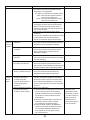
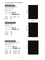
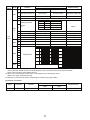
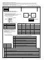
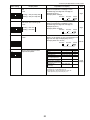
<Error code display by self-diagnosis and actions to be taken for service (summary)>
Present and past error codes are logged and displayed on the wired remote controller and control board of outdoor unit.
Actions to be taken for service, which depends on whether or not the trouble is reoccurring at service, are summarized in the
table below. Check the contents below before investigating details.
Unit conditions at service
Error code
Actions to be taken for service (summary)
Displayed
Judge what is wrong and take a corrective action according
to “10-4. Self-diagnosis action table”.
The trouble is reoccurring.
Not displayed
Logged
Conduct trouble shooting and ascertain the cause of the
trouble according to “10-5. Troubleshooting by inferior
phenomena”.
Consider the temporary defects such as the work of
protection devices in the refrigerant circuit including
compressor, poor connection of wiring, noise and etc.
Re-check the symptom, and check the installation
environment, refrigerant amount, weather when the
trouble occurred, matters related to wiring and etc.
Reset error code logs and restart the unit after finishing
service.
There is no abnormality concerning of parts such as
electrical component, controller board, remote controller
and etc.
The trouble is not reoccurring.
Not logged
Re-check the abnormal symptom.
Conduct trouble shooting and ascertain the cause of the
trouble according to “10-5. Troubleshooting by inferior
phenomena”.
Continue to operate unit for the time being if the cause
is not ascertained.
There is no abnormality concerning of parts such as
electrical component, controller board, remote controller
and etc.
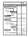
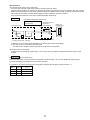
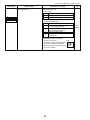
10-2. CHECK POINT UNDER TEST RUN
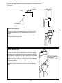
(1) Before test run
• After installation of indoor and outdoor units, piping work and electric wiring work, re-check that there is no refrigerant leakage, loosened connections and incorrect polarity.
• Measure impedance between the ground and the power supply terminal block (L1, L2) on the outdoor unit by 500V Megger
and check that it is 1.0M" or over.
w Do not use 500V Megger to indoor/outdoor connecting wire terminal block (S1, S2, S3) and remote controller terminal
block (1, 2). This may cause malfunction.
• Make sure that test run switch (SW4) is set to OFF before turning on power supply.
• Turn on power supply 12 hours before test run in order to protect compressor.
• For specific models which requires higher ceiling settings or auto-recovery feature from power failure, make proper changes
of settings referring to the description of “12. FUNCTION SETTING”.
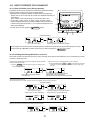
Make sure to read operation manual before test run. (Especially items to secure safety.)
28
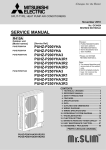
"TEST RUN" and the currently selected
operation mode are displayed alternately.
Displays the remaining
test run time.
Operating procedures
1. Turn on the main power supply.
2. Press TEST button twice.
The TEST RUN appears on the screen.
3. Press OPERATION SWITCH
button.
Cooling mode: Check if cool air blows and water is drained.
Heating mode: Check if warm air blows. (It takes a little
while until warm air blows.)
F
4. Press AIR DIRECTION button. Check for correct motion of auto-vanes.
5. Check the outdoor unit fan for
correct running.
While the room temperature display on the remote
controller is “PLEASE WAIT”, the remote controller is disabled.
Wait until “PLEASE WAIT” disappears before using remote controller.
“PLEASE WAIT” appears for about 2 minutes after power
supply is turned on. +1
[TEST] button
The outdoor unit features automatic capacity control to
provide optimum fan speeds. Therefore, the fan keeps
running at a low speed to meet the current outside air
condition unless it exceeds its available maximum power.
Then, in actuality, the fan may stop or run in the reverse
direction depending on the outside air, but this does not
mean malfunction.
6. Press the ON/OFF button to reset the test run in progress.
Pipe (liquid) temperature
7. Register the contact number.
• In case of test run, the OFF timer will be activated, and the test run will automatically stop after 2 hours.
• The room temperature display section shows the pipe temperature of indoor units during the test run.
• Check that all the indoor units are running properly in case of simultaneous twin operation. Malfunctions may not be displayed regardless of incorrect wiring.
w1 After turning on the power supply, the system will go into startup mode, “PLEASE WAIT” will blink on the display section
of the room temperature, and lamp (green) of the remote controller will blink.
As to INDOOR BOARD LED, LED1 will be lit, LED2 will either be lit in case the address is 0 or turned off in case the
address is not 0. LED3 will blink.
As to OUTDOOR BOARD LED, LED1 (green) and LED2 (red) will be lit. (After the startup mode of the system finishes,
LED2 (red) will be turned off.)
In case OUTDOOR BOARD LED is digital display,
— and —
will be displayed alternately every second.
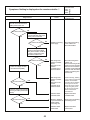
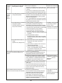
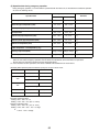
• If one of the above operations does not function correctly, the causes written below should be considered. Find causes from
the symptoms.
The below symptoms are under test run mode. “startup” in the table means the display status of w1 written above.
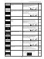
Symptoms in test run mode
OUTDOOR BOARD LED Display
Remote Controller Display
< > indicates digital display.
After “startup” is displayed, only
Remote controller displays “PLEASE
green lights up. <00>
WAIT”, and cannot be operated.
After “startup” is displayed,
green (once) and red (once)
After power is turned on, “PLEASE WAIT” blink alternately. <F1>
is displayed for 3 minutes, then error code
After “startup” is displayed,
is displayed.
green (once) and red (twice)
blink alternately. <F3, F5, F9>
After “startup” is displayed,
green (twice) and red (once)
No display appears even when remote
blink alternately. <EA. Eb>
controller operation switch is turned on.
After “startup” is displayed, only
(Operation lamp does not light up.)
green lights up. <00>
Display appears but soon disappears
even when remote controller is operated.
After “startup” is displayed, only
green lights up. <00>
Cause
• After power is turned on, “PLEASE WAIT” is displayed for 2
minutes during system startup. (Normal)
• Incorrect connection of outdoor terminal block (L1, L2, and
S1, S2, S3.)
• Outdoor unit’s protection device connector is open.
• Incorrect wiring between the indoor and outdoor unit (Polarity
is wrong for S1, S2, S3.)
• Remote controller transmission wire is short.
• There is no outdoor unit of address 0.
(Address is other than 0.)
• Remote controller transmission wire is open.
• After canceling function selection, operation is not possible for
about 30 seconds. (Normal)
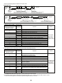
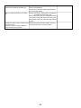
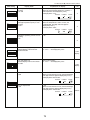
w Press the remote controller’s CHECK button twice to perform self-diagnosis. See the table below for the contents of LCD
display.
LCD
P1
P2
P4
P5
P6
P8
P9
Fb
Contents of inferior phenomena
Abnormality of room temperature thermistor
Abnormality of pipe temperature thermistor/Liquid
Abnormality of drain sensor/Float switch connector open
Drain overflow protection is working.
Freezing/overheating protection is working.
Abnormality of pipe temperature
Abnormality of pipe temperature thermistor/Cond./Eva
Abnormality of indoor controller board
LCD
U1~UP
F3~F9
E0~E5
E6~EF
---FFFF
PA
Contents of inferior phenomena
Malfunction outdoor unit
Malfunction outdoor unit
Remote controller transmitting error
Indoor/outdoor unit communication error
No error history
No applied unit
Forced compressor stop(due to water leakage abnormality)
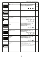
See the table below for details of the LED display (LED 1, 2, 3) on the indoor controller board.
LED1 (microprocessor power supply)
LED2 (remote controller)
LED3 (indoor/outdoor communication)
Lights when power is supplied.
Lights when power is supplied for wired remote controller.
The indoor unit should be connected to the outdoor unit with address “0” setting.
Flashes when indoor and outdoor unit are communicating.
29
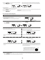
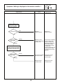
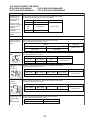
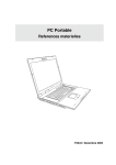
Test run [for wireless remote controller]
COOL
TEST
RUN
TEMP
ON/OFF
FAN
AUTO STOP
VANE
AUTO START
MODE
,
CHECK LOUVER
min
TEST RUN
SET
h
RESET
CLOCK
Measure an impedance between the power supply terminal block on
the outdoor unit and ground with a 500V Megger and check that it is
equal to or greater than 1.0M".
1 Turn on the main power to the unit.
TEST RUN
2 Press the
button twice continuously.
(Start this operation from the turned off status of remote controller
display.)
TEST RUN
and current operation mode are displayed.
3 Press the MODE (
) button to activate COOL mode, then
check whether cool air is blown out from the unit.
4 Press the MODE (
) button to activate HEAT mode, then
check whether warm air is blown out from the unit.
5 Press the FAN button and check whether strong air is blown out
from the unit.
VANE
6 Press the
button and check whether the auto vane operates
properly.
7 Press the ON/OFF button to stop the test run.
Note:
• Point the remote controller towards the indoor unit receiver
while following steps 2 to 7.
• It is not possible to run in FAN, DRY or AUTO mode.
30
10-3. HOW TO PROCEED "SELF-DIAGNOSIS"
10-3-1. When a Problem Occurs During Operation
If a problem occurs in the air conditioner, the indoor and outdoor units will stop,
and the problem is shown in the remote controller display.
[CHECK] and the refrigerant address are displayed on the temperature
display, and the error code and unit number are displayed alternately as
shown below.
(If the outdoor unit is malfunctioning, the unit number will be "00".)
In the case of group control, for which remote controller controls
multiple refrigerant systems, the refrigerant address and error code of the
unit that first experienced trouble (i.e., the unit that transmitted the error
code) will be displayed.
To clear the error code, press the
ON/OFF button.
(Alternating Display)
Error code (2 or 4 digits)
Address (3 digits) or unit number (2 digits)
When using remote-/local-controller combined operation, cancel the error code after turning off remote operation. During
central control by a MELANS controller, cancel the error code by pressing the
ON/OFF button.
10-3-2. Self-Diagnosis During Maintenance or Service
Since each unit has a function that stores error codes, the latest check code can be recalled even if it is cancelled by the remote
controller or power is shut off.
Check the error code history for each unit using the remote controller.
Switch to self-diagnosis mode.
Set the unit number or refrigerant address you want to diagnose.
Press the [TEMP] buttons (
Press the CHECK
button twice within 3 seconds. The display content
will change as shown below.
and
) to select the desired number
or address. The number (address) changes between [01] and [50] or [00]
and [15].
The refrigerant address will begin to blink
approximately 3 seconds after being
selected and the self-diagnosis process will begin.
Unit number or refrigerant address
to be diagnosed
Display self-diagnosis results.
<When there is error code history>
(For the definition of each error code, refer to the indoor unit's installation manual or service handbook.)
(Alternating Display)
Error code (2 or 4 digits)
Address (3 digits) or unit number (2 digits)
<When there is no error code history>
Reset the error history.
Display the error history in the diagnosis result display screen (see step ).
31
<When there is no corresponding unit>
Press the
ON/OFF button twice within 3 seconds. The self-diagnosis
address or refrigerant address will blink.
When the error history is reset, the display will look like the one shown below.
However, if you fail to reset the error history, the error content will be displayed again.
Cancel self-diagnosis.
Self-diagnosis can be cancelled by the following 2 methods.
Press the
CHECK
Press the
button twice within 3 seconds.
ON/OFF button.
Self-diagnosis will be cancelled and the screen will return to the previous state in effect before the start
of self-diagnosis.
Self-diagnosis will be cancelled and the indoor unit will stop.
10-3-3. Remote Controller Diagnosis
If the air conditioner cannot be operated from the remote controller, diagnose the remote controller as explained below.
First, check that the power-on indicator is lit.
If the correct voltage (DC12 V) is not supplied to the remote controller, the
indicator will not light.
If this occurs, check the remote controller's wiring and the indoor unit.
Power on indicator
Switch to the remote controller self-diagnosis mode.
Press the CHECK
button for 5 seconds or more. The display content will
Press the FILTER button to start self-diagnosis.
change as shown below.
Remote controller self-diagnosis result
[When the remote controller is functioning correctly]
[When the remote controller malfunctions]
(Error display 1) "NG" blinks. ©The remote controller's transmitting-receiving circuit is defective.
Check for other possible causes, as there is no problem with the remote
controller.
The remote controller must be replaced with a new one.
[Where the remote controller is not defective, but cannot be operated.]
(Error display 2) [E3], [6833] or [6832] blinks. © Transmission is not possible.
There might be noise or interference on the transmission path, or the indoor unit
or other remote controllers are defective. Check the transmission path and other
controllers.
(Error display 3) "ERC" and the number of data errors are displayed.
© Data error has occurred.
The number of data errors is the difference between the number of bits sent from
the remote controller and the number actually transmitted through the transmission path. If such a problem is occurring, the transmitted data is affected by noise,
etc. Check the transmission path.
When the number of data errors is "02":
Transmission data from remote controller
Transmission data on transmission path
To cancel remote controller diagnosis
Press the
CHECK button for 5 seconds or more. Remote controller diagnosis will be cancelled, "PLEASE WAIT" and operation lamp will blink. After
approximately 30 seconds, the state in effect before the diagnosis will be restored.
32
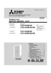
10-3-4. Malfunction-diagnosis method by wireless remote controller
<In case of trouble during operation>
When a malfunction occurs to air conditioner, both indoor unit and outdoor unit will stop and operation lamp blinks to inform
unusual stop.
<Malfunction-diagnosis method at maintenance service>
[Procedure]
1. Press the CHECK button twice.
• "CHECK" lights, and refrigerant
address "00" blinks.
• Check that the remote controller's
display has stopped before continuing.
2. Press the temperature
buttons.
• Select the refrigerant address of the
indoor unit for the self-diagnosis.
Note: Set refrigerant address using the
outdoor unit’s DIP switch (SW1).
(For more information, see the
outdoor unit installation manual.)
Refrigerant
address
display
CHECK
CHECK
display
Temperature
button
TEMP
ON/OFF
ON/OFF
button
MODE
FAN
AUTO STOP
VANE
AUTO START
CHECK LOUVER
CHECK
button
min
TEST RUN
SET
h
RESET
CLOCK
HOUR
button
3. Point the remote controller at the • If an air conditioner error occurs, the
sensor on the indoor unit and
indoor unit's sensor emits an intermitpress the HOUR button.
tent buzzer sound, the operation lamp
blinks, and the error code is output.
(It takes 3 seconds at most for error
code to appear.)
4. Point the remote controller at the • The check mode is cancelled.
sensor on the indoor unit and
press the ON/OFF button.
33
• Refer to the following tables for details on the check codes.
[Output pattern A]
Beeper sounds
OPERATION
INDICATOR
lamp blink
pattern
Beep
Beep Beep Beep
Off
Beep
1st
2 nd
3 rd
nth
On
On
On
On
Beep Beep
1st
Off
On
2 nd · · · Repeated
On
0.5 sec. Approx. 2.5 sec. 0.5 sec. 0.5 sec.
Self-check Approx. 2.5 sec. 0.5 sec. 0.5 sec. 0.5 sec.
starts
(Start signal
Number of blinks/beeps in pattern indicates the check
Number of blinks/beeps in pattern indicates
received)
the check code in the following table
code in the following table (i.e., n=5 for “P5”)
[Output pattern B]
Beeper sounds
OPERATION
INDICATOR
lamp blink
pattern
Beep
Beep Beep Beep
1st
Off
On
Approx. 3 sec.
Self-check Approx. 2.5 sec.
starts
(Start signal
received)
2nd
3 rd
On
On
On
0.5 sec. 0.5 sec. 0.5 sec.
Beep
Beep
nth
1st
On
Off
0.5 sec. Approx. 2.5 sec.
Number of blinks/beeps in pattern indicates the check
code in the following table (i.e., n=5 for “U2”)
On
Approx. 3 sec.
Beep
2 nd · · · Repeated
On
On
0.5 sec. 0.5 sec.
Number of blinks/beeps in pattern indicates
the check code in the following table
[Output pattern A] Errors detected by indoor unit
Wireless remote controller Wired remote controller
Beeper sounds/OPERATION
INDICATOR lamp blinks
Check code
(Number of times)
1
P1
P2
2
P9
3
E6,E7
4
P4
P5
5
PA
6
P6
7
EE
8
P8
9
E4, E5
–
10
–
11
12
Fb
E0, E3
–
–
E1, E2
Symptom
Intake sensor error
Pipe (TH2) sensor error
Pipe (TH5) sensor error
Indoor/outdoor unit communication error
Drain sensor error/Float switch connector open
Drain pump error
Forced compressor stop (due to water leakage abnormality)
Freezing/Overheating protection operation
Communication error between indoor and outdoor units
Pipe temperature error
Remote controller signal receiving error
–
–
Indoor unit control system error (memory error, etc.)
Remote controller transmission error
Remote controller control board error
Remark
As for indoor
unit, refer to
indoor unit's
service manual.
[Output pattern B] Errors detected by unit other than indoor unit (outdoor unit, etc.)
Wireless remote controller Wired remote controller
Beeper sounds/OPERATION
INDICATOR lamp blinks
Check code
(Number of times)
1
E9
2
3
4
5
UP
U3,U4
UF
U2
6
U1,Ud
7
8
9
U5
U8
U6
11
U9,UH
Symptom
Indoor/outdoor unit communication error
(Transmitting error) (Outdoor unit)
Compressor overcurrent interruption
Open/short of outdoor unit thermistors
Compressor overcurrent interruption (When compressor locked)
Abnormal high discharging temperature/insufficient refrigerant
Abnormal high pressure (63H operated)/Overheating
protection operation
Abnormal temperature of heatsink
Outdoor unit fan protection stop
Compressor overcurrent interruption/Abnormal of power module
Abnormality such as overvoltage or voltage shortage and
abnormal synchronous signal to main circuit/Current sensor error
–
–
Other errors
Remark
For details, check
the LED display
of the outdoor
controller board.
–
12
–
13
Others
14
*1 If the beeper does not sound again after the initial 2 beeps to confirm the self-check start signal was received and
the OPERATION INDICATOR lamp does not come on, there are no error records.
*2 If the beeper sounds 3 times continuously “beep, beep, beep (0.4 + 0.4 + 0.4 sec.)” after the initial 2 beeps to confirm
the self-check start signal was received, the specified refrigerant address is incorrect.
34
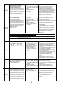
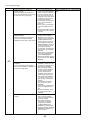
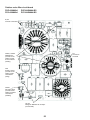
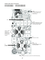
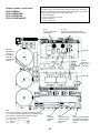
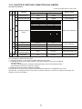
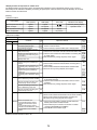
10-4. SELF-DIAGNOSIS ACTION TABLE
<Abnormalities detected when the power is turned on> (Note 1) Refer to indoor unit section for code P and code E.
Error Code
Abnormal point and detection method
Judgment and action
Case
1 No voltage is supplied to terminal 1 Check following items.
block (TB1) of outdoor unit.
a) Power supply breaker
a) Power supply breaker is
b) Connection of power supply terminal block
turned off.
(TB1)
c) Connection of power supply terminal block
b) Contact failure or disconnec(TB1)
tion of power supply terminal
c) Open phase (L1 or L2 phase)
2 Electric power is not charged to 2 Check following items.
a) Connection of power supply terminal block
power supply terminal of out(TB1)
door power circuit board.
b) Connection of terminal on outdoor power
a) Contact failure of power
circuit board
supply terminal
A12-A24N: Disconnection of connector R or S
b) Open phase on the outdoor
Refer to 10-9.
power circuit board
A30-A42N: Disconnection of connector TABT
A12-A24N :Disconnection of
or TABS Refer to 10-9.
connector R or S
A30-A42N :Disconnection of
connector TABT or TABS
3 Electric power is not supplied to 3 Check connection of the connector (CNDC)
on the outdoor controller circuit board.
outdoor controller circuit board.
Check connection of the connector, LD1 and
a) Disconnection of connector
LD2 for A12-A24N and CNDC for A30-A36N,
(CNDC)
on the outdoor power circuit board.
Refer to 10-9.
None
—
4 Disconnection of reactor (DCL
or ACL)
4 Check connection of reactor. (DCL or ACL)
A12-A24N: Check connection of “LO” and
“NO” on the outdoor noise filter circuit board.
Check connection of “R” and “S” on the
outdoor power circuit board.
A30-A42N: Check connection of “L1” and “L2”
on the active filter module. (ACTM)
Refer to 10-9.
5 Disconnection of outdoor noise 5 a) Check connection of outdoor noise filter
circuit board.
filter circuit board or parts failb) Replace outdoor noise filter circuit board.
ure in outdoor noise filter circuit
Refer to 10-9.
board
As for A30-A42N type, it is
especially needed to check the
resistance RS1 on the noise
filter circuit board.
6 Defective outdoor power circuit 6 Replace outdoor power circuit board.
board
7 Defective outdoor controller
circuit board
F3
(5202)
7 Replace controller board (When items above
are checked but the units cannot be repaired).
63L connector open
1 Disconnection or contact failure 1 Check connection of 63L connector on
Abnormal if 63L connector circuit is open for
of 63L connector on outdoor
outdoor controller circuit board.
3 minutes continuously after power supply.
controller circuit board
Refer to 10-9.
63L: Low-pressure switch
2 Disconnection or contact failure 2 Check the 63L side of connecting wire.
of 63L
<A42N only>
3 63L is operating due to refriger- 3 Check refrigerant pressure.
ant leakage or defective parts.
Charge additional refrigerant.
Check continuity by tester.
Replace the parts if the parts are defective.
4 Defective outdoor controller
4 Replace outdoor controller circuit board.
circuit board
35
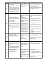
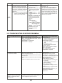
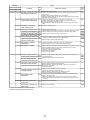
Error Code
F5
(5201)
F9
(4119)
EA
(6844)
Eb
(6845)
EC
(6846)
Abnormal point and detection method
Case
Judgment and action
63H connector open
1 Disconnection or contact failure
Abnormal if 63H connector circuit is open for
of 63H connector on outdoor
3 minutes continuously after power supply.
controller circuit board
63H: High-pressure switch
2 Disconnection or contact failure
of 63H
3 63H is operating due to
defective parts.
4 Defective outdoor controller
circuit board
1 Check connection of 63H connector on
outdoor controller circuit board.
Refer to 10-9.
2 Check the 63H side of connecting wire.
2 connector open
1 Disconnection or contact failure
Abnormal if both 63H and 63L connector
of connector (63H,63L) on
circuits are open for 3 minutes continuously
outdoor controller circuit board.
after power supply.
2 Disconnection or contact failure
of 63H, 63L
63H: High-pressure switch
3 63H and 63L are operating due
63L: Low-pressure switch
to defective parts.
4 Defective outdoor controller
<A42N only>
board
1 Check connection of connector (63H,63L) on
outdoor controller circuit board.
Refer to 10-9.
2 Check the 63H and 63L side of connecting
wire.
3 Check continuity by tester.
Replace the parts if the parts are defective.
4 Replace outdoor controller circuit board.
1 Contact failure or miswiring of
indoor/outdoor unit connecting
wire
2 Diameter or length of indoor/
outdoor unit connecting wire is
out of specified capacity.
3 4 or more indoor units are
connected to 1 outdoor unit.
4 Defective transmitting receiving
circuit of outdoor controller
circuit board
5 Defective transmitting receiving
circuit of indoor controller board
6 Defective indoor power board
7 2 or more outdoor units have
refrigerant address “0” .
(In case of group control)
8 Noise has entered into power
supply or indoor / outdoor unit
connecting wire.
1 Check disconnection or looseness or polarity
of indoor/outdoor unit connecting wire of
indoor and outdoor units.
Indoor/outdoor unit connector
miswiring, excessive number of units
1. Outdoor controller circuit board can
automatically check the number of
connected indoor units. Abnormal if the
number cannot be checked automatically
due to miswiring of indoor/outdoor unit
connecting wire and etc. after power is
turned on for 4 minutes.
2. Abnormal if outdoor controller circuit
board recognizes excessive number of
indoor units.
3 Check continuity by tester.
Replace the parts if the parts are defective.
4 Replace outdoor controller circuit board.
2 Check diameter and length of indoor/outdoor
unit connecting wire.
Total wiring length: 80m [262ft]
(including wiring connecting each indoor unit
and between indoor and outdoor unit)
Also check if the connection order of flat
cable is S1, S2, S3.
3 Check the number of indoor units that are
connected to one outdoor unit. (If EA is
detected)
4~6 Turn the power off once, and on again to
check.
Replace outdoor controller circuit board,
indoor controller board or indoor power
board if abnormality occurs again.
Miswiring of indoor/outdoor unit
connecting wire (converse wiring or
disconnection)
Outdoor controller circuit board can
automatically set the unit number of indoor
units.
Abnormal if the indoor unit number cannot be set within 4 minutes after power on
because of miswiring (converse wiring or
disconnection) of indoor/outdoor unit connecting wire.
1 Contact failure or miswiring of 7 Check if refrigerant addresses (SW1-3 to
indoor/outdoor unit connecting
SW1-6 on outdoor controller circuit board) are
wire
overlapping in case of group control system.
2 Diameter or length of indoor/
outdoor unit connecting wire is
8 Check transmission path, and remove the
out of specified capacity.
cause.
4 Defective transmitting receiving
circuit of outdoor controller circuit
w The descriptions above, 1-8, are for EA, Eb
board
and EC.
5 Defective transmitting receiving
circuit of indoor controller board
6 Defective indoor power board
7 2 or more outdoor units have
refrigerant address “0” .
(In case of group control)
8 Noise has entered into power
supply or indoor/outdoor unit
connecting wire.
Start-up time over
The unit cannot finish start-up process
within 4 minutes after power on.
1 Contact failure of indoor/
outdoor unit connecting wire
2 Diameter or length of indoor/
outdoor unit connecting wire is
out of specified capacity.
7 2 or more outdoor units have
refrigerant address “0” .
(In case of group control)
8 Noise has entered into power
supply or indoor/outdoor unit
connecting wire.
36
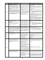
<Abnormalities detected while unit is operating>
Error Code
Abnormal point and detection method
High pressure (High-pressure switch
63H operated)
Abnormal if high-pressure switch 63H operated ( w ) during compressor operation.
w 4.15 MPa [602PSIG]
63H: High-pressure switch
U1
(1302)
High discharging temperature
High comp.shell temperature
(1) Abnormal if discharge temperature
thermistor (TH4) exceeds 125:[257ûF]
or 110: [230ûF] continuously for 5 minutes.
Abnormal if condenser/evaporator temperature thermistor (TH5) exceeds 40:
[104ûF] during defrosting and discharge
temperature thermistor (TH4) exceeds
110: [230ûF].
Case
1 Short cycle of indoor unit
2 Clogged filter of indoor unit
3 Decreased airflow caused by
dirt of indoor fan
4 Dirt of indoor heat exchanger
5 Locked indoor fan motor
6 Malfunction of indoor fan motor
7 Defective operation of stop
valve (Not full open)
8 Clogged or broken pipe
9 Locked outdoor fan motor
0 Malfunction of outdoor fan
motor
1 Short cycle of outdoor unit
2 Dirt of outdoor heat exchanger
3 Decreased airflow caused by
defective inspection of outside
temperature thermistor
(It detects lower temperature
than actual temperature.)
4 Disconnection or contact failure
of connector (63H) on outdoor
controller board
5 Disconnection or contact failure
of 63H connection
6 Defective outdoor controller
board
7 Defective action of linear
expansion valve
8 Malfunction of fan driving
circuit
Judgment and action
1~6Check indoor unit and repair the defect.
7 Check if stop valve is fully open.
8 Check piping and repair the defect.
9~2 Check outdoor unit and repair the defect.
3 Check the inspected temperature of outside
temperature thermistor on LED display.
(SW2 on A-Control Service Tool : Refer to
10-10.)
4~6 Turn the power off and check F5 is
displayed when the power is on again.
When F5 is displayed, refer to “Judgment
and action” for F5.
7 Check linear expansion valve.
Refer to 10-6, 7.
8 Replace outdoor controller board.
1 Overheated compressor opera- 1 Check intake superheat.
tion caused by shortage of
Check leakage of refrigerant.
refrigerant
Charge additional refrigerant.
2 Defective operation of stop
2 Check if stop valve is fully open.
valve
3 Defective thermistor
34 Turn the power off and check if U3 is displayed when the power is on again.
4 Defective outdoor controller
board
When U3 is displayed, refer to “Judgement
and action” for U3.
5 Defective action of linear
5 Check linear expansion valve.
expansion valve
Refer to 10-6, 7.
(2) Abnormal if discharge superheat
(Cooling: TH4 – TH5 / Heating: TH4 –
TH6) increases.
All the conditions in A or B are detected
simultaneously for 10 minutes continuously after 6 minutes past from compressor start-up (including the thermostat indication or recovery from defrostU2
ing).
(TH4: 1102)
<Condition A>
(TH32: 1132)
• Heating mode
• When discharge superheat is less
than 70 deg [126ûF].
• When the TH6 temp is more than the
value obtained by TH7 – 5 deg [9ûF].
• When the condensing temp of TH5 is
less than 35: [95ûF].
<Condition B>
• During comp. operation (Cooling and
Heating)
• When discharge superheat is less
than 80 deg [144ûF] in cooling.
• When discharge super heat is less
than 90 deg [162ûF] in heating.
• When condensing temp of TH6 is
more than –40: [–40ûF] (In cooling
only).
(3) Abnormal if comp.shell temperature
thermistor (TH32) exceeds 125: [257ûF].
37
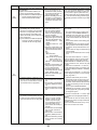
Error Code
Abnormal point and detection method
Open/short circuit of discharge
temperature thermistor (TH4)/
comp.shell thermistor (TH32)
Abnormal if open (3: [37ûF] or less) or
U3
short (217: [422ûF] or more) is detected
(TH4 :5104)
during compressor operation.
(TH32: 5132)
(Detection is inoperative for 10 minutes
of compressor starting process and for 10
minutes after and during defrosting.)
U4
(TH3:5105)
(TH6:5107)
(TH7:5106)
(TH8:5110)
Open/short of outdoor unit thermistors
(TH3, TH6, TH7, and TH8)
Abnormal if open or short is detected
during compressor operation.
Open detection of thermistors TH3 and
TH6 is inoperative for 10 seconds to 10
minutes after compressor starting and 10
minutes after and during defrosting.
WCheck which unit has abnormality in its
thermistor by switching the mode of
SW2. (PAC-SK52ST)
(Refer to 10-10.)
Symbol
TH3
TH6
TH7
TH8
U5
(4230)
1 Disconnection or contact failure 1 Check connection of connector (TH3,TH6/TH7)
on the outdoor controller circuit board.
of connectors
Check connection of connector (CN3) on the
Outdoor controller circuit
outdoor power circuit board.
board: TH3,TH6/TH7
Check breaking of the lead wire for thermistor
Outdoor power circuit board:
(TH3,TH6,TH7,TH8). Refer to 10-9.
CN3
2 Check resistance value of thermistor
2 Defective thermistor
(TH3,TH6,TH7,TH8) or check temperature by
3 Defective outdoor controller
microprocessor.
circuit board
(Thermistor / TH3, TH6, TH7, TH8 : Refer to
10-6.)
(SW2 on A-Control Service Tool: Refer to
10-10.)
3 Replace outdoor controller circuit board.
WEmergency operation is available in case of
abnormalities of TH3, TH6 and TH7.
Refer to 10-8.
)
(
Thermistors
Name
Thermistor <Outdoor pipe>
Thermistor <Outdoor 2-phase pipe>
Thermistor <Outdoor>
Thermistor <Heatsink>
Temperature of heatsink
Abnormal if heatsink thermistor (TH8)
detects temperature indicated below.
A12, 18, 42N ·············84:, 183ûF
A24, 30, 36N ·············81:, 177ûF
Judgment and action
Case
1 Disconnection or contact
1 Check connection of connector (TH4/TH32)
on the outdoor controller circuit board.
failure of connector (TH4/TH32)
Check breaking of the lead wire for
on the outdoor controller circuit
thermistor (TH4/TH32). Refer to 10-9.
board
2 Check resistance value of thermistor (TH4/
2 Defective thermistor
TH32) or temperature by microprocessor.
3 Defective outdoor controller
(Thermistor/TH4/TH32: Refer to 10-6.)
circuit board
(SW2 on A-Control Service Tool: Refer to
10-10.)
3 Replace outdoor controller board.
Open detection
Short detection
– 40[-40°F] or below
– 40[-40°F] or below
– 40[-40°F] or below
– 27[-17°F] or below
90[194°F] or above
90[194°F] or above
90[194°F] or above
102[216°F] or above
1 The outdoor fan motor is
locked.
2 Failure of outdoor fan motor
3 Air flow path is clogged.
4 Rise of ambient temperature
5 Defective thermistor
6 Defective input circuit of
outdoor power circuit board
7 Failure of outdoor fan drive
circuit
12 Check outdoor fan.
3 Check airflow path for cooling.
4 Check if there is something which causes
temperature rise around outdoor unit.
(Upper limit of ambient temperature is 46:
[114ûF].)
Turn off power, and on again to check if U5
is displayed within 30 minutes.
If U4 is displayed instead of U5, follow the
action to be taken for U4.
5 Check resistance value of thermistor (TH8)
or temperature by microprocessor.
(Thermistor/TH8: Refer to 10-6.)
(SW2 on A-Control Service Tool: Refer to
10-10.)
6 Replace outdoor power circuit board.
7 Replace outdoor controller circuit board.
U6
(4250)
Power module
1 Outdoor stop valve is closed.
Check abnormality by driving power module 2 Decrease of power supply voltage
in case overcurrent is detected.
3 Looseness, disconnection or
(UF or UP error condition)
converse of compressor wiring
connection
4 Defective compressor
5 Defective outdoor power circuit
board
1 Open stop valve.
2 Check facility of power supply.
3 Correct the wiring (U·V·W phase) to
compressor. Refer to 10-9 (Outdoor power
circuit board).
4 Check compressor referring to 10-6.
5 Replace outdoor power circuit board.
1 Check or replace the DC fan motor.
U8
(4400)
Outdoor fan motor
1 Failure in the operation of
Abnormal if the rotational frequency of fan
the DC fan motor
motor is not detected during DC fan motor 2 Failure in the outdoor circuit
operation.
controller board
Fan motor rotational frequency is abnormal
if;
• 100 rpm or below detected continuously
for 15 seconds at 20:[68ûF] or more
outside air temperature.
• 50 rpm or below or 1500 rpm or more
detected continuously for 1 minute.
38
2 Check the voltage of the outdoor circuit
controller board during operation.
3 Replace the outdoor circuit controller
board. (when the failure is still indicated
even after performing the action 1
above.)
Error Code
U8
(4400)
Abnormal point and detection method
Case
Outdoor fan motor
1 Failure in the operation of the
Abnormal if the rotational frequency of fan
DC fan motor
motor is not detected during DC fan motor 2 Failure in the outdoor circuit
operation.
controller board
Fan motor rotational frequency is abnormal if;
• 100 rpm or below detected continuously
for 15 seconds at 20: [68ûF] or more
outside air temperature.
• 50 rpm or below or 1500 rpm or more
detected continuously for 1 minute.
Overvoltage or voltage shortage and
synchronous signal to main circuit
U9
(4220)
UF
(4100)
1 Decrease of power supply voltage
2 Disconnection of compressor
Abnormal if any of followings are detected
wiring
during compressor operation;
3 Disconnection or loose con• Decrease of DC bus voltage to 310V
nection of CN52C
• Instantaneous decrease of DC bus volt4 Defective PFC module of outage to 200V
door power board (A12, 18,
• Increase of DC bus voltage to
24N only)
A12, 18, 24N : 420V
5 Defective ACT module (A30,
A30, 36, 42N : 400V
36, 42N only)
• Decrease of input current of outdoor unit 6 Defective ACT module drive
to 0.5A only if operation frequency is
circuit of outdoor power circuit
more than or equal to 40Hz or compresboard (A30, 36, 42N only)
sor current is more than or equal to 5A.
7 Disconnection or loose con• Abnormal power synchronous (zero cross)
nection of CNAF (A30, 36, 42N
signal
only)
• PFC error (overcurrent) when the current 8 Defective 52C drive circuit of
peak of input current increase A12, 18,
outdoor noise filter circuit board
24N: 47A (peak)
9 Disconnection or loose
connection of CN5 on the
outdoor power circuit board
0 Disconnection or loose
connection of CN2 on the
outdoor power circuit board
Compressor overcurrent interruption
(When compressor locked)
Abnormal if overcurrent of DC bus or
compressor is detected within 30 seconds
after compressor starts operating.
1 Stop valve is closed.
2 Decrease of power supply
voltage
3 Looseness, disconnection or
converse of compressor wiring
connection
4 Defective compressor
5 Defective outdoor power board
UH
(5300)
Current sensor error
1 Disconnection of compressor
• Abnormal if current sensor detects –1.5A
wiring
to 1.5A during compressor operation.
(This error is ignored in case of test run
2 Defective circuit of current
mode.)
sensor on outdoor power
w This error is ignored in case of test run
circuit board
mode.
3 Decrease of power supply
• It’s abnormal for 38A the input current or
voltage
10 seconds continuous 34A or more.
Low pressure (63L operated)
Abnormal if 63L is operated (under0.03MPa) during compressor operation.
63L: Low-pressure switch
UL
(1300)
(A42N only)
1 Stop valve of outdoor unit is
closed during operation.
2 Disconnection or loose connection of connector (63L) on outdoor
controller board
3 Disconnection or loose
connection of 63L
4 Defective outdoor controller board
5 Leakage or shortage of refrigerant
6 Malfunction of linear expansion
valve
39
Judgment and action
1 Check or replace the DC fan motor.
2 Check the voltage of the outdoor circuit controller board during operation.
3 Replace the outdoor circuit controller board.
(when the failure is still indicated even after
performing the action 1 above.)
1 Check the facility of power supply.
2 Correct the wiring (U·V·W phase) to compressor. Refer to 10-9 (Outdoor power circuit
board).
3 Check CN52C wiring.
4 Replace outdoor power circuit board.
(A12, 18, 24N only)
5 Replace ACT module. (A30, 36, 42N only)
6 Replace outdoor power circuit board.
(A30, 36, 42N only)
7 Check CNAF wiring. (A30, 36, 42N only)
8 Replace outdoor noise filter circuit board.
9 Check CN5 wiring on the outdoor power
circuit board.
Refer to 10-9.
0 Check CN2 wiring on the outdoor power
circuit board.
Refer to 10-9.
1 Open stop valve.
2 Check facility of power supply.
3 Correct the wiring (U·V·W phase) to
compressor.
Refer to 10-9 (Outdoor power circuit board).
4 Check compressor.
Refer to 10-6.
5 Replace outdoor power circuit board.
1 Correct the wiring (U·V·W phase) to
compressor. Refer to 10-9 (Outdoor power
circuit board).
2 Replace outdoor power circuit board.
3 Check the facility of power supply.
1 Check stop valve.
2~4 Turn the power off and on again to check
if F3 is displayed on restarting.
If F3 is displayed, follow the F3 processing
direction.
5 Correct to proper amount of refrigerant.
6 Check linear expansion valve.
Refer to 10-6.
Error Code
UP
(4210)
E0
or
E4
E1
or
E2
E3
or
E5
Abnormal point and detection method
Case
Judgment and action
Compressor overcurrent interruption
1 Stop valve of outdoor unit is
Abnormal if overcurrent DC bus or comclosed.
pressor is detected after compressor starts 2 Decrease of power supply voltoperating for 30 seconds.
age
3 Looseness, disconnection or
converse of compressor wiring
connection
4 Defective fan of indoor/outdoor
units
5 Short cycle of indoor/outdoor
units
6 Defective input circuit of outdoor controller board
7 Defective compressor
1 Open stop valve.
2 Check facility of power supply.
3 Correct the wiring (U·V·W phase) to
compressor. Refer to 10-9 (Outdoor power
circuit board).
4 Check indoor/outdoor fan.
5 Solve short cycle.
6 Replace outdoor controller circuit board.
7 Check compressor.
Refer to 10-6.
W Before the replacement of the outdoor
controller circuit board, disconnect the wiring
to compressor from the outdoor power circuit
board and check the output voltage among
phases, U, V, W, during test run. No defect
on board if voltage among phases (U-V, V-W
and W-U) is same. Make sure to perform the
voltage check with same performing frequency.
Remote controller transmission error
(E0)/signal receiving error (E4)
1 Abnormal if main or sub remote controller cannot receive normally any transmission from indoor unit of refrigerant
address “0” for 3 minutes.
(Error code : E0)
2 Abnormal if sub-remote controller could
not receive for any signal for 2 minutes.
(Error code: E0)
1 Check disconnection or looseness of indoor
unit or transmission wire of remote controller.
2 Set one of the remote controllers “main”.
If there is no problem with the action above.
3 Check wiring of remote controller.
• Total wiring length: max. 500m [1640ft]
(Do not use cable o 3 or more.)
• The number of connecting indoor units:
max. 16 units
• The number of connecting remote controller: max. 2 units
1 Abnormal if indoor controller board can
not receive any data normally from
remote controller board or from other
indoor controller board for 3 minutes.
(Error code: E4)
2 Indoor controller board cannot receive
any signal from remote controller for 2
minutes. (Error code: E4)
1 Contact failure at transmission
wire of remote controller
2 All remote controllers are set
as “sub” remote controller. In
this case, E0 is displayed on
remote controller, and E4 is
displayed at LED (LED1, LED2)
on the outdoor controller circuit
board.
3 Miswiring of remote controller
4 Defective transmitting receiving
circuit of remote controller
5 Defective transmitting receiving
circuit of indoor controller board
of refrigerant address “0”.
6 Noise has entered into the
transmission wire of remote
controller.
Remote controller control board
1 Defective remote controller
1 Abnormal if data cannot be normally
read from the nonvolatile memory of the
remote controller control board.
(Error code: E1)
When the above-mentioned problem of 1~3
are not applied.
4 Diagnose remote controllers.
a) When “RC OK” is displayed,
remote controllers have no problem.
Turn the power off, and on again to check.
If abnormality generates again, replace
indoor controller board.
b) When “RC NG” is displayed,
replace remote controller.
c) When “RC E3” or "ERC 00-66" is displayed, noise may be causing abnormality.
* If the unit is not normal after replacing indoor
controller board in group control, indoor controller board of address “0” may be abnormal.
1 Replace remote controller.
2 Abnormal if the clock function of remote
controller cannot be normally operated.
(Error code: E2)
Remote controller transmission error (E3)/
signal receiving error (E5)
1 Abnormal if remote controller could not
find blank of transmission path for 6 seconds and could not transmit.
(Error code: E3)
2 Remote controller receives transmitted
data at the same time, compares the
data, and when detecting it, judges
different data to be abnormal 30
continuous times. (Error code: E3)
1 Set a remote controller to main, and the
1 2 remote controller are set as
other to sub.
“main.”
(In case of 2 remote controllers)
2 Remote controller is connected 2 Remote controller is connected with only one
with 2 indoor units or more.
indoor unit.
3 Repetition of refrigerant
3 The address changes to a separate setting.
address
4 Defective transmitting receiving 4~6 Diagnose remote controller.
circuit of remote controller
a) When “RC OK” is displayed, remote controllers have no problem.
1 Abnormal if indoor controller board could 5 Defective transmitting receiving
Turn the power off, and on again to check.
not find blank of transmission path.
circuit of indoor controller board
When becoming abnormal again, replace
(Error code: E5)
6 Noise has entered into transindoor controller board.
2 Indoor controller board receives transmission wire of remote controlb) When “RC NG”is displayed, replace
mitted data at the same time, compares
ler.
remote controller.
the data, and when detecting it, judges
c) When “RC E3”or “ERC 00-66”is displayed,
different data to be abnormal 30
noise may be causing abnormality.
continuous times. (Error code: E5)
40
Error Code
E6
(6840)
E8
(6840)
E9
(6841)
EF
(6607
or
6608)
Abnormal point and detection method
Case
Judgment and action
Indoor/outdoor unit communication
error (Signal receiving error)
1 Abnormal if indoor controller board could
not receive any signal normally for 6
minutes after turning the power on.
2 Abnormal if indoor controller board could
not receive any signal normally for 3
minutes.
3 Consider the unit as abnormal under
the following condition; When 2 or more
indoor units are connected to an outdoor unit, indoor controller board could
not receive a signal for 3 minutes from
outdoor controller circuit board, a signal
which allows outdoor controller circuit
board to transmit signals.
w Check LED display on outdoor controller
circuit board. (Connect A-Control service tool
(PAC-SG50ST))
1 Contact failure, short circuit or
Refer to EA~EC item if LED displays EA~AC.
miswiring (converse wiring) of
indoor/outdoor unit connecting 1 Check disconnecting or looseness of indoor
/outdoor unit connecting wire of indoor unit
wire
or outdoor unit.
2 Defective transmitting receivCheck all the units in case of twin indoor unit
ing circuit of outdoor controller
system.
circuit board
3 Defective transmitting receiving 2~4 Turn the power off, and on again to check.
If abnormality generates again, replace
circuit of indoor controller board
indoor controller board or outdoor controller
4 Noise has entered into indoor/
circuit board.
outdoor unit connecting wire.
5 Turn the power off, and detach fan motor from con5 Defective fan motor
nector (CNF1,2). Then turn the power on again.
6 Defective rush current resistor
If abnormality is not displayed, replace fan motor.
If abnormality is displayed, replace outdoor
controller circuit board.
6 Check RS1 on outdoor noise filter board with
tester. If open is detected, replace the board.
w Other indoor controller board may have
defect in case of twin indoor unit system.
Indoor/outdoor unit communication
error (Signal receiving error)
(Outdoor unit)
(1) Abnormal if outdoor controller circuit
board could not receive anything
normally for 3 minutes.
1 Check disconnection or looseness of indoor/
1 Contact failure of indoor/outoutdoor unit connecting wire of indoor or outdoor unit connecting wire
door units.
2 Defective communication circuit
of outdoor controller circuit board 2~4 Turn the power off, and on again to
check. Replace indoor controller board or
3 Defective communication circuit
outdoor controller circuit board if abnormalof indoor controller board
ity is displayed again.
4 Noise has entered into indoor/
outdoor unit connecting wire.
Indoor/outdoor unit communication
error (Transmitting error) (Outdoor unit)
(1) Abnormal if “0” receiving is detected 30
times continuously though outdoor controller circuit board has transmitted “1”.
(2) Abnormal if outdoor controller circuit
board could not find blank of transmission
path for 3 minutes.
1 Indoor/outdoor unit connecting 1 Check disconnection or looseness of indoor/
wire has contact failure.
outdoor unit connecting wire.
2 Defective communication circuit 2~4 Turn the power off, and on again to
of outdoor controller circuit board
check. Replace outdoor controller circuit
3 Noise has entered power supply.
board if abnormality is displayed again.
4 Noise has entered indoor/outdoor unit connecting wire.
Non defined error code
This code is displayed when non defined
error code is received.
1 Noise has entered transmission 12 Turn the power off, and on again to check.
Replace indoor controller board or outdoor
wire of remote controller.
controller circuit board if abnormality is
2 Noise has entered indoor/outdisplayed again.
door unit connecting wire.
3 Replace outdoor unit with power-inverter type
3 Outdoor unit is not a poweroutdoor unit.
inverter models.
4 Model name of remote control- 4 Replace remote controller with MA remote
controller.
ler is PAR-S25A.
Serial communication error
1. Abnormal if serial communication
between outdoor controller circuit
board and outdoor power circuit board
is defective.
1 Breaking of wire or contact
12 Check connection of each connector CN2
failure of connector CN2
and CN4 between the outdoor controller
between the outdoor controller
circuit board and the outdoor power circuit
circuit board and the outdoor
board.
power circuit board
2 Breaking of wire or contact
failure of connector CN4
between the outdoor controller
circuit board and the outdoor
power circuit board
3 Defective communication circuit 3 Replace outdoor power circuit board.
of outdoor power circuit board
4 Defective communication circuit 4 Replace outdoor controller circuit board.
of outdoor controller circuit board
for outdoor power circuit board
2. Abnormal if communication between
outdoor controller circuit board and
M-NET board is not available.
1 Breaking of wire or contact
1 Check disconnection, looseness, or breaking of
failure of connector between
connection wire between outdoor controller ciroutdoor controller circuit board
cuit board (CNMNT) and M-NET board (CN5).
and M-NET board
2 Contact failure of M-NET board 2 Check disconnection, looseness, or breaking of
power supply line
connection wire between outdoor controller circuit board (CNMNT) and M-NET board (CND).
3 Noise has entered into M-NET
transmission wire.
3 Check M-NET transmission wiring method.
Ed
(0403)
41
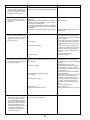
Error Code
P8
Abnormal point and detection method
Pipe temperature
1 Slight temperature difference
<Cooling mode>
between indoor room
Detected as abnormal when the pipe temtemperature and pipe <liquid
perature is not in the cooling range 3 minor condenser/evaporator>
utes after compressor start and 6 minutes
temperature thermistor
after the liquid or condenser/evaporator pipe
• Shortage of refrigerant
is out of cooling range.
• Disconnected holder of pipe
Note 1) It takes at least 9 min. to detect.
<liquid or condenser/
Note 2) Abnormality P8 is not detected in
evaporator> thermistor
drying mode.
• Defective refrigerant circuit
Cooling range : Indoor pipe temperature
2 Converse connection of
(TH2 or TH5) – intake temperature
extension pipe (on plural units
(TH1) [ -3 deg [-5.4ûF]
connection)
TH: Lower temperature between liquid pipe 3 Converse wiring of indoor/
temperature and condenser/
outdoor unit connecting wire
evaporator temperature
(on plural units connection)
4 Defective detection of indoor
<Heating mode>
room temperature and pipe
When 10 seconds have passed after the
<condenser/evaporator>
compressor starts operation and the hot
temperature thermistor
adjustment mode has finished, the unit is
5 Stop valve is not opened
detected as abnormal when condenser/
completely.
evaporator pipe temperature is not in heating range within 20 minutes.
Note 3) It takes at least 27 minutes to
detect abnormality.
Note 4) It excludes the period of defrosting
(Detection restarts when defrosting
mode is over)
Heating range : 3 deg [5.4ûF] [ (Condenser/
Evaporator temperature (TH5) –
intake temperature (TH1))
<M-NET communication error>
Error Code
A0
(6600)
A2
(6602)
A3
(6603)
1~4
(
Check pipe <liquid or condenser/
evaporator> temperature with room
temperature display on remote
controller and outdoor controller circuit
board.
Pipe <liquid or condenser/evaporator>
temperature display is indicated by
setting SW2 of outdoor controller circuit
board as follows.
Conduct temperature check with outdoor
controller circuit board after connecting
‘A-Control Service Tool (PAC-SK52ST)’.
)
Temperature display of indoor liquid pipe
Indoor 1
1
2
3
4
5
6
Temperature display of indoor condenser/
evaporator pipe Indoor 1
1
2
3
4
5
6
ON
ON
OFF
OFF
Temperature display of indoor liquid pipe
Indoor 2
1
2
3
4
5
6
Temperature display of indoor condenser/
evaporator pipe Indoor 2
1
2
3
4
5
6
ON
ON
OFF
OFF
A-Control Service Tool
SW2 setting
23Check converse connection of extension
pipe or converse wiring of indoor/outdoor
unit connecting wire.
(Note) “Indoor unit” in the text indicates M-NET board in outdoor unit.
Abnormal point and detection method
Case
Address duplicate definition
1 There are 2 or more same
This error is displayed when transmission
address of controller of outfrom the units of same address is detected.
door unit, indoor unit, FRESH
Note) The address and attribute displayed
MASTER, or LOSSNAY.
at remote controller indicate the con- 2 Noise has entered into transtroller that detected abnormality.
mission signal and signal was
transformed.
Hardware error of transmission
processor
Transmission processor intended to transmit “0”, but “1” appeared on transmission
wire.
Note) The address and attribute display at
remote controller indicate the controller that detected abnormality.
Judgment and action
Case
1 Error is detected if waveform is
Judgment and action
Search the unit with same address as abnormality occurred. If the same address is found, turn off
the power supply of outdoor unit and indoor unit
and FRESH MASTER or LOSSNAY at the same
time for 2 minutes or more after the address is
corrected, and turn the power on again.
Check transmission waveform or noise on
transmission wire.
1 If the works of transmission wire is done
with the power on, turn off the power supply
of outdoor unit and indoor unit and FRESH
MASTER or LOSSNAY at the same time for
2 minutes or more, and turn the power on
again.
transformed when wiring works of
transmission wire of outdoor unit,
indoor unit, FRESH MASTER or
LOSSNAY are done, or polarity is
changed with the power on and
transmission data collide each other.
2 Defective transmitting receiving
2 Check transmission waveform or noise on
circuit of transmission processor
transmission wire.
3 Transmission data is changed by
the noise on transmission.
BUS BUSY
1 Transmission processor could
1 Check if transmission wire of indoor unit,
not transmit signal because short
1. Overtime error by collision damage
FRESH MASTER, LOSSNAY, or remote concycle voltage of noise and the
Abnormal if transmitting signal is not
troller is not connected to terminal block for
like have entered into transmispossible for 8-10 minutes continuously
central control (TB7) of outdoor unit.
sion wire continuously.
because of collision of transmission.
2 Check if transmission wire of indoor unit,
2. Data could not reach transmission wire 2 Transmission quantity has
FRESH MASTER or LOSSNAY is not conincreased and transmission is
for 8-10 minutes continuously because
nected to terminal block for transmission wire
not possible because there was
of noise or etc.
of outdoor unit.
wiring mistake of terminal block
Note) The address and attribute displayed
for transmission wire (TB3) and
at remote controller indicate the conterminal block for central control
troller that detected abnormality.
(TB7) in outdoor unit.
3 Transmission are mixed with
others and occupation rate on
transmission wire rose because
of defective repeater (a function
to connector or disconnect transmission of control and central
control system) of outdoor unit,
then abnormality is detected.
42
3 Check if terminal block for transmission wire
(TB3) and terminal block for central control
(TB7) are not connected.
4 Check transmission waveform or noise on
transmission wire.
Error Code
Abnormal point and detection method
Case
Judgment and action
A6
(6606)
Communication error with communication processor
Defective communication between unit
processor and transmission processor
Note) The address and attribute display at
remote controller indicate the controller that detected abnormality.
1 Data of transmission processor or unit processor is not
transmitted normally because
of accidental trouble such as
noise or lightning surge.
2 Address forwarding from unit
processor is not transmitted
normally because of defective
transmission processor hardware.
Turn off the power supply of outdoor unit and
indoor unit and FRESH MASTER or LOSSNAY
at the same time for 2 minutes or more, and
turn the power on again. System returns to
normal if abnormality was accidental malfunction. If the same abnormality generates again,
abnormality-generated controller may be defective.
NO ACK signal
1. Transmitting side controller detects
abnormal if a massage was transmitted
but there is no reply (ACK) that a message was received. Transmitting side
detects abnormality every 30 seconds, 6
times continuously.
Note) The address and attribute displayed
at remote controller is indicate the
controller that did not reply (ACK).
Common factor that has no relation with abnormality source.
1 The unit of former address
does not exist as address
switch has changed while the
unit was energized.
2 Extinction of transmission wire
voltage and signal is caused by
over-range transmission wire.
• Maximum distance ······ 200m
[656ft]
• Remote controller line .. (12m
[39ft])
3 Extinction of transmission wire
voltage and signal is caused by
type-unmatched transmission
wire.
Type······
With shield wireCVVS, CPEVS
With normal wire (no shield)VCTF, VCTFK, CVV
CVS, VVR, VVF, VCT
Diameter ····1.25mm2 [AWG16]
or more
4 Extinction of transmission wire
voltage and signal is caused
by over-numbered units.
5 Accidental malfunction of
abnormality-detected controller
(noise, lightning surge)
6 Defective of abnormality generated controller
Always try the followings when the error
“A7” occurs.
A7
(6607)
1 Turn off the power supply of outdoor unit
and indoor unit and FRESH MASTER or
LOSSNAY at the same time for 2 minutes or
more, and turn the power on again. If malfunction was accidental, the unit returns to
normal.
2 Check address switch of abnormality generated address.
3 Check disconnection or looseness of abnormality generated or abnormality detected
transmission wire (terminal block and connector)
4 Check if tolerance range of transmission wire
is not exceeded.
5 Check if type of transmission wire is correct
or not.
If there were some troubles of 1-5 above,
repair the defective, then turn off the power
supply of outdoor unit and indoor unit and
FRESH MASTER or LOSSNAY at the same
time for 2 minutes or more, and turn the power
on again.
• If there was no trouble with 1-5 above in
single refrigerant system (one outdoor unit),
controller of displayed address or attribute is
defective.
• If there was no trouble with 1-5 above in different refrigerant system (2 or more outdoor
units), judge with 6.
2. If displayed address or attribute is out1 Contact failure of transmission 6 If address of abnormality source is the
address that should not exist, there is the
wire of outdoor unit or indoor
door unit, Indoor unit detects abnormality
unit that memorizes nonexistent address
unit
when indoor unit transmitted to outdoor
information. Delete useless address informa2 Disconnection of transmission
unit and there was no reply (ACK).
tion with manual setting function of remote
connector (CN2M) of outdoor
controller.
unit
Only the system FRESH MASTER or
3 Defective transmitting receiving
LOSSNAY are connected to, or the system
circuit of outdoor unit or indoor
that is equipped with group setting of differunit
ent refrigerant system.
3. If displayed address or attribute is indoor 1 During group operation with
indoor unit of multi- refrigerant
unit, remote controller detects abnormalsystem, if remote controller
ity when remote controller transmitted to
transmit to indoor unit while
indoor unit and there was no reply (ACK).
outdoor unit power supply
of one refrigerant system is
turned off or within 2 minutes of restart, abnormality is
detected.
2 Contact failure of transmission
wire of remote controller or
indoor unit
3 Disconnection of transmission
connector (CN2M) of indoor
unit
4 Defective transmitting receiving
circuit of indoor unit or remote
controller
If there was no trouble with 1-6 above, replace
the controller board of displayed address or
attribute.
If the unit does not return to normal, multi-controller board of outdoor unit may be defective
(repeater circuit).
Replace multi-controller board one by one to
check if the unit returns to normal.
Continued to the next page.
43
From the previous page.
Error Code
Abnormal point and detection method
Case
4. If displayed address or attribute is
1 During group operation with
indoor unit of multi- refrigerant
remote controller,
system, if indoor unit transmit
Indoor unit detects abnormality when
to remote controller while outindoor unit transmitted to remote controldoor unit power supply of one
ler and there was no reply (ACK).
refrigerant system is turned off
or within 2 minutes of restart,
abnormality is detected.
2 Contact failure of transmission
wire of remote controller or
indoor unit
3 Disconnection of transmission
connector (CN2M) of indoor
unit
4 Defective transmitting receiving
circuit of indoor unit or remote
controller
5. If displayed address or attribute is
1 During sequential operation
of indoor unit and FRESH
FRESH MASTER,
MASTER of other refrigerant
Indoor unit detects abnormality when
system, if indoor unit transmits
indoor unit transmitted to FRESH
to FRESH MASTER while
MASTER and there was no reply (ACK).
outdoor unit power supply of
same refrigerant system with
FRESH MASTER is turned off
or within 2 minutes of restart,
abnormality is detected.
2 Contact failure of transmission
wire of indoor unit or FRESH
MASTER
3 Disconnection of transmission
connector (CN2M) of indoor
unit or FRESH MASTER
4 Defective transmitting receiving
circuit of indoor unit or FRESH
MASTER
A7
(6607)
6. If displayed address or attribute is
1 If the power supply of
LOSSNAY is turned off, indoor
LOSSNAY,
unit detects abnormality when
Indoor unit detects abnormality when
it transmits to LOSSNAY.
indoor unit transmitted to LOSSNAY and
2 During sequential operation
there was no reply (ACK).
of indoor unit and LOSSNAY
of other refrigerant system,
if indoor unit transmits to
LOSSNAY while outdoor unit
power supply of same refrigerant system with LOSSNAY
is turned off or within 2 minutes of restart, abnormality is
detected.
3 Contact failure of transmission wire of indoor unit of
LOSSNAY
4 Disconnection of transmission
connector (CN2M) of indoor
unit
5 Defective transmitting receiving circuit of indoor unit or
LOSSNAY
7. If displayed address or attribute is nonexistent,
1 The unit of former address
does not exist as address
switch has changed while the
unit was energized.
2 Abnormality is detected
when indoor unit transmitted because the address
of FRESH MASTER and
LOSSNAY are changed after
sequential operation of FRESH
MASTER and LOSSNAY by
remote controller.
44
Judgment and action
Same as mentioned in “A7” of the previous
page.
Error Code
A8
(6608)
Abnormal point and detection method
Case
M-NET NO RESPONSE
1 Transmitting condition is
repeated fault because of
Abnormal if a message was transmitted
noise and the like.
and there were reply (ACK) that message
2 Extension of transmission wire
was received, but response command
voltage and signal is caused
does not return. Transmitting side detects
by over-range transmission
abnormality every 30 seconds, 6 times
wire.
continuously.
• Maximum distance ······ 200m
Note) The address and attribute displayed
[656ft]
at remote controller indicate the con• Remote controller line ····(12m
troller that did not reply (ACK).
[39ft])
3 Extension of transmission wire
voltage and signal is caused
by type-unmatched transmission wire.
Type······
With shield wireCVVS, CPEVS
With normal wire (no shield)VCTF, VCTFK, CVV
CVS, VVR, VVF, VCT
Diameter ····1.25mm2 [AWG16]
or more
4 Accidental malfunction of
abnormality-generated
controller
Judgment and action
1 Check transmission waveform or noise on
transmission wire.
2 Turn off the power supply of outdoor unit
and indoor unit and FRESH MASTER or
LOSSNAY at the same time for 2 minutes or
more, and turn the power on again. If malfunction was accidental, the unit returns to
normal. If the same abnormality generates
again, controller of displayed address and
attribute may be defective.
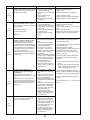
10-5. TROUBLESHOOTING BY INFERIOR PHENOMENA
Phenomena
1. Remote controller display does not
work.
Factor
1DC12V is not supplied to remote controller.
(Power supply display
is not indicated on LCD.)
2DC12~15V is supplied to remote controller, however,
no display is indicated.
• “PLEASE WAIT” is not displayed.
• “PLEASE WAIT” is displayed.
Countermeasure
1Check LED2 on indoor controller board.
(1) When LED2 is lit.
Check the remote controller wiring for
breaking or contact failure.
(2) When LED2 is blinking.
Check short circuit of remote controller
wiring.
(3) When LED2 is not lit.
Refer to phenomena No.3 below.
2Check the following.
• Failure of remote controller if “PLEASE
WAIT” is not displayed
• Refer to phenomena No.2 below if
“PLEASE WAIT” is displayed.
2. “PLEASE WAIT” display is remained 1At longest 2 minutes after the power supply “PLEASE 1Normal operation
on the remote controller.
WAIT” is displayed to start up.
2Self-diagnosis of remote controller
2Communication error between the remote controller
3”PLEASE WAIT” is displayed for 6 minand indoor unit
utes at most in case of indoor/outdoor unit
communication error. Check LED3 on
3Communication error between the indoor and outdoor
unit
indoor controller board.
(1)When LED3 is not blinking.
4Outdoor unit protection device connector is open.
Check indoor/outdoor connecting wire
for miswiring.
(Converse wiring of S1 and S2, or
break of S3 wiring.)
(2)When LED3 is blinking.
Indoor/outdoor connecting wire is normal.
4Check LED display on outdoor controller
circuit board. Refer to 10-10.
Check protection device connector (63L
and 63H) for contact failure.
Refer to 10-9.
3. When pressing the remote controller 1After cancelling to select function from the remote
operation switch the OPERATION
controller, the remote controller operation switch will
display is appeared but it will be
not be accepted for approx. 30 seconds.
turned off soon.
45
1Normal operation
Phenomena
4. Even controlling by the wireless
remote controller no beep is heard
and the unit does not start operating. Operation display is indicated
on wireless remote controller.
Factor
Countermeasure
1The pair number settings of the wireless remote
1Check the pair number settings.
controller and indoor controller board are mismatched.
5. When operating by the wireless
remote controller, beep sound is
heard, however, unit does not start
operating.
1No operation for 2 minutes at most after the power
1Normal operation
supply ON.
2Hand-held remote controller operation is prohibited.
2Normal operation
• Remote controlling adaptor is connected to CN32
on the indoor controller board.
• Hand-held remote controller operation is prohibited
by centralised controller etc. since it is connected to
MELANS.
3Refer to factor of phenomena No.2 on previous page. 3Check the details of phenomena No.2 on
previous page.
6. Remote controller display works
1Refrigerant shortage
normally and the unit performs cooling operation, however, the capacity
cannot be fully obtained. (The air
does not cool well.)
2Filter clogging
1 If refrigerant leaks, discharging temperature rises and LEV opening increases.
Inspect leakage by checking the temperature and opening.
Check pipe connections for gas leakage.
2 Open intake grille and check the filter.
Clean the filter by removing dirt or dust
on it.
3 If the filter is clogged, indoor pipe temperature rises and discharging pressure
increases. Check if heat exchanger is
clogged by inspecting discharging pressure.
Clean the heat exchanger.
4 Remove the shield.
3Heat exchanger clogging
4Air duct short cycle
7. Remote controller display works
1 Discharging temperature and indoor heat
1Linear expansion valve fault
normally and the unit performs heatexchanger temperature does not rise.
Opening cannot be adjusted well due to linear expaning operation, however, the capacity
Inspect the failure by checking discharging
sion valve fault.
cannot be fully obtained.
pressure.
Replace linear expansion valve.
2 If refrigerant leaks, discharging tempera2Refrigerant shortage
ture rises and LEV opening increases.
Inspect leakage by checking the temperature and opening.
Check pipe connections for gas leakage.
3 Check the insulation.
3Lack of insulation for refrigerant piping
4 Open intake grill and check the filter. Clean
4Filter clogging
the filter by removing dirt or dust on it.
5 If the filter is clogged, indoor pipe temperature rises and discharging pressure
5Heat exchanger clogging
increases. Check if heat exchanger is
clogged by inspecting discharging pressure.
Clean the heat exchanger.
6 Remove the shield.
6Air duct short cycle
7 Check refrigerant system during operation.
7Bypass circuit of outdoor unit fault
12Normal operation
8. 1For 3 minutes after temperature
(For protection of compressor)
adjuster turns off, the compressor
will not start operating even if
temperature adjuster is turned on.
2For 3 minutes after temperature
adjuster turns on, the compressor
will not stop operating even if
temperature adjuster is turned off.
(Compressor stops operating
immediately when turning off by
the remote controller.)
46
12Normal operation
Symptoms: “PLEASE WAIT” is kept being displayed on the remote controller.
Diagnosis flow
Cause
Inspection method and
troubleshooting
Check the display time of “PLEASE WAIT”
after turning on the main power.
6 minutes
or more
How long is “PLEASE WAIT”
kept being displayed on the
remote controller?
2 minutes
or less
2 to 6
minutes
Are any error codes
displayed on the
remote controller?
Check the LED display of the
outdoor controller circuit board.
Are any error codes
displayed on the LED?
• “PLEASE WAIT”
• Normal
will be displayed
The start-up diagnosis will
during the start-up
be over in around 2 minutes.
diagnosis after turning
on the main power.
NO
YES
YES
• Miswiring of indoor/
outdoor connecting
wire
• Breaking of indoor/
outdoor connecting
wire (S3)
• Defective indoor
controller board
• Defective outdoor
controller circuit
board
NO
• Defective indoor
controller board
• Defective remote
controller
47
• Refer to “Self-diagnosis
action table” in order to
solve the trouble.
• In case of communication
errors, the display of
remote controller may not
match the LED display of
the outdoor unit.
Symptoms: Nothing is displayed on the remote controller Diagnosis flow
Cause
LED display of the indoor
controller board
LED1 :
LED2 :
LED3 :
Inspection method and
troubleshooting
Check the voltage between S1
and S2 on the terminal block
(TB4) of the indoor unit.
AC 187V to AC 253V?
YES
NO
Check the voltage among L1 and L2
on the terminal block (TB1) of the
outdoor power circuit board.
AC 187V to AC 253V?
NO
• Troubles concerning
power supply
• Check the power wiring
to the outdoor unit.
• Check the breaker.
• Bad wiring of the
outdoor controller
board
• The fuses on the
outdoor
controller circuit
board are blown.
• Check the wiring of the
outdoor unit.
• Check if the wiring is bad.
Check if the fuses are blown.
The fuses on the outdoor
controller circuit board will
be blown when the indoor
/outdoor connecting wire
short-circuits.
• Bad wiring of the
outdoor controller
board
• The fuses on the
outdoor
controller circuit
board are blown.
• Check if miswiring, breaking
or poor contact is causing this
problem. Indoor/outdoor
connecting wire is polarized
3-core type. Connect the
indoor unit and the outdoor
unit by wiring each pair of
S1, S2 and S3 on the both
side of indoor/outdoor
terminal blocks.
• Defective indoor
controller board
• Replace the indoor
controller board.
YES
Check the voltage between S1
and S2 on the terminal block
(TB1) of the outdoor unit which
is used to connect the indoor
unit and the outdoor unit.
AC 187V to AC 253V?
NO
YES
Check the voltage of indoor
controller board (CN2D).
DC 12V to DC 16V?
YES
NO
Check the voltage of the unit after
removing the indoor power board
(CN2S).
DC 12V to DC 16V?
YES
• Check if there is miswiring
• Miswiring, breaking
or poor connection of or breaking of wire.
indoor/outdoor
connecting wire
NO
• Defective indoor
power board
48
• Replace the indoor
power board.
Symptoms: Nothing is displayed on the remote controller Diagnosis flow
Cause
LED display of the indoor
controller board
LED1 :
LED2 :
LED3 :
or
Inspection method and
troubleshooting
Check the voltage between S1 and S2 on the terminal block (TB4)
of the indoor unit.
NO
AC 187V to AC 253V?
YES
Not lighting.
Check the status
of the indoor controller
board LED3 display.
Check the looseness or disconnection
of the indoor/outdoor connecting wire.
Blinking
Are there looseness or
disconnection of the indoor/
outdoor connecting wire?
YES
• Breaking or poor
• Fix the breaking or poor
contact of the indoor/ contact of the indoor/outdoor
outdoor connecting
connecting wire.
wire
NO
Check the refrigerant address of
the outdoor unit. (SW1-3 to 1-6)
NO
Is the refrigerant
address “0”?
YES
Check the LED display of the
outdoor unit after turning on the
main power again.
Not displayed.
Is anything displayed?
Displayed.
Is “EA” or “Eb”
displayed?
• Normal
Only the unit which
has the refrigerant
address “0” supplies
power to the remote
controller.
• Set the refrigerant
address to “0”. In case of
the multiple grouping
system, recheck the
refrigerant address again.
• Defective outdoor
controller circuit
board
• Replace the outdoor
controller circuit board.
• Defective outdoor
controller circuit
board
• Replace the outdoor
controller circuit board.
• Defective indoor
controller board
• Replace the indoor controller
board of the indoor unit which
does not operate.
NO
YES
Is “E8” displayed?
YES
NO
Can the unit be restarted?
Can all the indoor
unit be operated?
Check the voltage between S2
and S3 on the terminal block of
the outdoor unit.
DC 17V to DC 28V?
NO
YES
• Not abnormal.
• Influence of
electromagnetic noise There may be the influence
of electromagnetic noise.
Check the transmission wire
and get rid of the causes.
NO
YES
49
• Defective outdoor
power circuit board
• Replace the outdoor
power circuit board.
• Defective indoor
power board
• Replace the indoor
power board.
Symptoms: Nothing is displayed on the remote controller Diagnosis flow
Cause
LED display of the indoor
controller board
LED1 :
LED2 :
or
LED3 : —
Inspection method and
troubleshooting
Check the voltage of the
terminal block (TB6) of
the remote controller.
DC 10V to DC 16V?
YES
• Defective
remote controller
• Replace the
remote controller.
NO
Check the status
of the LED2.
Lighting
• Check if there is breaking
• Breaking or poor
contact of the remote or poor contact of the
remote controller wire.
controller wire
Check the voltage of the
terminal block (TB5)
connecting the remote
controller wire.
If it is not between DC 10V
and DC16V, the indoor
controller board must be
defective.
Blinking
Check the status of the LED2
after disconnecting the remote
controller wire from the terminal
block (TB5) of the indoor unit.
Check the status
of the LED2.
Lighting
• The remote controller • Check if the remote
wire short-circuits
controller wire is
short-circuited.
Blinking
• Defective indoor
controller board
50
• Replace the indoor
controller board.
• Before repair
Frequent calling from customers
Phone Calls From Customers
How to Respond
Note
Unit does The operating display of remote Check if power is supplied to air conditioner.
Nothing appears on the display unless power is
not operate
controller does not come on.
supplied.
at all.
Unit cannot be restarted for a Wait around 3 minutes to restart unit.
while after it’s stopped.
The air conditioner is in a state of being protected
by the microprocessor’s directive. Once the
compressor is stopped, the unit cannot be
restarted for 3 minutes. This control is also applied
when the unit is turned on and off by remote
controller or thermostat.
Error code appears and blinks Error code will be displayed if any protection
on the display of remote
devices of the air conditioner are actuated.
controller.
What is error code?
Remote
controller
“PLEASE WAIT” is displayed
on the screen.
Wait around 2 minutes.
An automatic startup test will be conducted for
2 minutes when power is supplied to the air
conditioner. “PLEASE WAIT” will be kept being
displayed while that time.
“FILTER” is displayed on the
screen.
This indicates that it is time to clean the air filters.
Clean the air filters. Press the FILTER button on
the remote controller twice to clear “FILTER” from
the display.
See the operation manual that came with the
product for how to clean the filters.
“STANDBY” is displayed on the This is displayed when the unit starts HEAT
operation, when the thermostat puts the
screen.
compressor in operation mode, or when the
outdoor unit ends DEFROST operation and
returns to HEAT operation.
The display will automatically disappear around
10 minutes later.
While “STANDBY” is displayed on the remote
controller, the airflow amount will be restricted
because the indoor unit’s heat exchanger is not
fully heated up. In addition to that, the up/down
vane will be automatically set to horizontal blow
in order to prevent cold air from directly blowing
out to human body. The up/down vane will return
to the setting specified by the remote controller
when “STANDBY” is released.
“DEFROST” is displayed on
the screen. (No air comes out
of the unit.)
The outdoor unit gets frosted when the outside
temperature is low and the humidity is high.
“DEFROST” indicates the DEFROST operation
is being performed to melt this frost. The
DEFROST operation ends in around 10 minutes
(at most 15 minutes).
During the DEFROST operation, the indoor unit’s
heat exchanger becomes cold, so the blower is
stopped. The up/down vane will be automatically
set to horizontal blow in order to prevent cold air
from directly blowing out to human body. The
display will turn into “STANDBY” when DEFROST
operation ends.
51
Refer to “SELF-DIAGNOSIS
ACTION TABLE”.
Check if servicing is
required for the error.
Display time of “FILTER”
depends on the model.
Long life filter: 2500 hrs.
Standard filter: 100 hrs.
Phone Calls From Customers
How to Respond
Note
The room cannot be cooled or heated sufficiently. Check the set temperature of remote controller.
The outdoor unit cannot be operated if the set
temperature is not appropriate.
The outdoor unit operates in the following modes.
COOL: When the set temperature is lower
than the room temperature.
HEAT: When the set temperature is higher
than the room temperature.
Check if filters are not dirty and clogged. If filters
are clogged, the airflow amount will be reduced
and the unit capacity will be lowered. See the
instruction manual that came with the product for
how to clean the filters.
Sound
A gas escaping sound is heard
comes out
sometimes.
from the air
conditioner.
A cracking sound is heard
sometimes.
Check there is enough space around the air
conditioner.
If there are any obstacles in the air intake or air outlet
of indoor/outdoor units, they block the airflow
direction so that the unit capacity will be lowered.
This is not a malfunction.
This is the sound which is heard when the flow of
refrigerant in the air conditioner is switched.
This is not a malfunction.
This is the sound which is heard when internal
parts of units expand or contract when the
temperature changes.
A buzzing sound is heard
sometimes.
This is not a malfunction.
This is the sound which is heard when the outdoor
unit starts operating.
A ticking sound is heard from
the outdoor unit sometimes.
This is not a malfunction.
This is the sound which is heard when the fan
of the outdoor unit is controlling the airflow amount
in order to keep the optimum operating condition.
A sound, similar to water
flowing, is heard from the unit.
This is not a malfunction.
This is the sound which is heard when the
refrigerant is flowing inside the indoor unit.
Something The fan speed does not match
is wrong
the setting of the remote
with the
controller during DRY
blower…..
operation.(No air comes out
sometimes during DRY
operation.)
This is not a malfunction. During the DRY
operation, the blower’s ON/OFF is controlled by
the microprocessor to prevent overcooling and to
ensure efficient dehumidification. The fan speed
cannot be set by the remote controller during DRY
operation.
The fan speed does not match
the setting of the remote
controller in HEAT operation.
This is not a malfunction.
1) When the HEAT operation starts, to prevent the
unit from blowing cold air, the fan speed is
gradually increased from 0 to the set speed,
in proportion to the temperature rise of the
discharged air.
2) When the room temperature reaches the set
temperature and the outdoor unit stops,
the unit starts the LOW AIR operation.
3) During the HEAT operation, the DEFROST
operation is performed to defrost the outdoor
unit. During the DEFROST operation, the
fan is stopped to prevent cold air coming
out of the indoor unit.
52
The up/down vane will be
automatically set to
horizontal blow in these
cases listed up on the left
(1)~3)). After a while, the
up/down vane will be
automatically moved
according to the setting of
the remote controller.
Phone Calls From Customers
Something Air blows out for a while after
HEAT operation is stopped.
is wrong
with the
blower…..
How to Respond
Note
This is not a malfunction.
The blower is operating just for cooling down the
heated-up air conditioner. This will be done within
1 minute.
This control is conducted only when the HEAT
operation is stopped with the electric heater ON.
However, this control is also
applied to the models which
has no electric heater.
Something The airflow direction is changed If the up/down vane is set to downward in COOL
is wrong
operation, it will be automatically set to horizontal
during COOL operation.
with the
blow by the microprocessor in order to prevent
airflow
water from dropping down.
direction….
“1 Hr.” will be displayed on the remote controller if
the up/down vane is set to downward with the fan
speed set to be less than “LOW”.
The airflow direction is changed In HEAT operation, the up/down vane is
automatically controlled according to the
during HEAT operation.
temperature of the indoor unit’s heat exchanger.
(The airflow direction cannot be
In the following cases written below, the up/down
set by remote controller.)
vane will be set to horizontal blow, and the setting
cannot be changed by remote controller.
1) At the beginning of the HEAT operation
2) While the outdoor unit is being stopped by
thermostat or when the outdoor unit gets started
to operate.
3) During DEFROST operation
The airflow direction will be back to the setting
of remote controller when the above situations
are released.
“STANDBY” will be displayed
on the remote controller in
case of 1) and 2).
“DEFROST” will be displayed
on the screen in case of 3).
The airflow direction does not
1) Check if the vane is set to a fixed position.
(Check if the vane motor connector is
change.
removed.)
(Up/down vane, left/right louver)
2) Check if the air conditioner has a function for
switching the air direction.
3) If the air conditioner doesn’t have that
function, “NOT AVAILABLE” will be displayed
on the remote controller when “AIR
DIRECTION” or “LOUVER” button is pressed.
The air conditioner starts operating even though Check if you set ON/OFF timer.
any buttons on the remote controller are not
The air conditioner starts operating at the time
pressed.
designated if ON timer has been set before.
Check if any operations are ordered by distant
control system or the central remote controller.
While “CENTRALLY CONTROLLED INDICATOR”
is displayed on the remote controller, the air
conditioner is under the control of external directive.
There might be a case that
“CENTRALLY CONTROLLED
INDICATOR” will not be
displayed.
Check if power is recovered from power failure
(black out).
The units will automatically start operating when
power is recovered after power failure (black out)
occurs. This function is called “auto recovery
feature from power ”.
The air conditioner stops even though any
Check if you set ON/OFF timer.
buttons on the remote controller are not pressed.
The air conditioner stops operating at the time
designated if OFF timer has been set before.
Check if any operations are ordered by distant
control system or the central remote controller.
While “CENTRALLY CONTROLLED INDICATOR” is
displayed on the remote controller, the air conditioner is
under the control of external directive.
53
There might be a case that
“CENTRALLY
CONTROLLED INDICATOR”
will not be displayed.
Phone Calls From Customers
How to Respond
A white mist is expelled from the indoor unit.
This is not a malfunction.
This may occur when the operation gets started in
the room of high humidity.
Water or moisture is expelled from the outdoor
unt.
Cooling: when pipes or piping joints are cooled, they
get sweated and water drips down.
Heating: water drips down from the heat exchanger.
* Use optional parts “Drain Socket” and “Drain pan”
if these water needs to be collected and drained out
for once.
The display of wireless remote controller gets dim Batteries are being exhausted. Replace them and
or does not come on.
press the reset button of remote controller.
The indoor unit does not receive a signal from
remote controller at a long distance.
54
Note
10-6. HOW TO CHECK THE PARTS
PUZ-A18/24/30/36/42NHA4
PUZ-A18/24/30/36/42NHA4-BS
PUY-A12/18/24/30/36/42NHA4
PUY-A12/18/24/30/36/42NHA4-BS
Check points
Parts name
Thermistor (TH3)
<Outdoor pipe>
Disconnect the connector then measure the resistance with a tester.
(At the ambient temperature 10~30, 50°F~86°F)
Thermistor (TH4)
<Discharge>
Abnormal
Normal
Thermistor (TH6)
<Outdoor 2-phase pipe>
TH4, TH32
160k~410k
TH3
Thermistor (TH7)
<Outdoor>
TH6
Thermistor (TH8)
<Heatsink>
TH8
Open or short
4.3k~9.6k
TH7
39k~105k
Thermistor (TH32)
<Shell>
Fan motor (MF1,MF2) Refer to next page.
Solenoid valve coil
<Four-way valve>
(21S4)
Measure the resistance between the terminals with a tester.
(At the ambient temperature 20, 68°F)
Normal
Abnormal
A18-36
A42
1500$150
2350$170
Open or short
Motor for compressor Measure the resistance between the terminals with a tester.
(Winding temperature 20, 68°F)
U
(MC)
Normal
Abnormal
V
A12, 18
A24, 30, 36
A42
W
0.320
0.880
0.266
Open or short
Linear expansion valve Disconnect the connector then measure the resistance with a tester.
(Winding temperature 20, 68°F)
(LEV-A)
For A12, 18
Normal
M
Abnormal
Red
1
Brown 2
Blue
3
Orange
4
Yellow 5
White
6
Red - White
Red - Orange
Brown - Yellow
Brown - Blue
Open or short
46$4
Linear expansion valve Disconnect the connector then measure the resistance with a tester.
(LEV-A)
(Winding temperature 20, 68°F)
For A24-42
M
Gray
Orange
Red
Yellow
Black
Abnormal
Normal
1
2
3
4
5
6
Solenoid valve coil
<Bypass valve>
(SV)
For A24-36 only
Gray - Black
Gray - Yellow
Gray - Red
46$3
Measure the resistance between the terminals with a tester.
(At the ambient temperature 20, 68°F)
Normal
1450$150
Abnormal
Open or short
55
Gray - Orange
Open or short
Check method of DC fan motor (fan motor / outdoor controller circuit board)
Notes
· High voltage is applied to the connecter (CNF1, 2) for the fan motor. Pay attention to the service.
· Do not pull out the connector (CNF1, 2) for the motor with the power supply on.
(It causes trouble of the outdoor controller circuit board and fan motor.)
Self check
Symptom : The outdoor fan cannot turn around.
Fuse check
Check the fuse (F5) on outdoor
controller board.
Did the fuse blow?
Yes
Replace outdoor controller board (C.B)
and fan motor (MF1, 2).
No
Wiring contact check
Contact of fan motor connector (CNF1, 2)
Is there contact failure?
Yes
Wiring recovery
No
Power supply check (Remove the connector (CNF1, 2))
Measure the voltage in the outdoor controller circuit board.
TEST POINT : VDC (between 1 (+) and 4 (-) of the fan connector): VDC DC250~330V
TEST POINT : VCC (between 5 (+) and 4 (-) of the fan connector): VCC DC15V
Is the voltage normal?
Yes
Replace the fan motor.
Yes
No
Check the operation of fan.
Replace outdoor
controller board.
NG
Replace outdoor controller board.
OK
Check the operation.
END
NG
Replace the fan motor.
56
OK
END
10-7. HOW TO CHECK THE COMPONENTS
<Thermistor feature chart>
50
Low temperature thermistors
• Thermistor <Outdoor pipe> (TH3)
• Thermistor <Outdoor 2-phase pipe> (TH6)
• Thermistor <Outdoor> (TH7)
Resistance (k)
40
Thermistor R0 = 15k" ± 3%
B constant = 3480 ± 2%
1
1
t (:): Rt =15exp{3480( 273+t – 273 )}
1
1
T (ûF): RT =15exp{3480( 273+(T– 32)/1.8 – 273 )}
30
20
10
0:[32ûF]
10:[50ûF]
20:[68ûF]
25:[77ûF]
15k"
9.6k"
6.3k"
5.2k"
30:[86ûF]
40:[104ûF]
4.3k"
3.0k"
0
Medium temperature thermistor
-20 -10 0 10 20 30 40 50 -4 -14 32 50 68 86 104122 °F
Temperature
200
• Thermistor <Heatsink> (TH8)
Thermistor R50 = 17k" ± 2%
B constant = 4170 ± 3%
150
0:[32ûF]
25:[77ûF]
50:[122ûF]
70:[158ûF]
90:[194ûF]
Resistance (k)
1
1
t (:): Rt =17exp{4170( 273+t – 323 )}
1
1
T (ûF): RT=17exp{4170( 273+(T– 32)/1.8 – 323 )}
180k"
50k"
17k"
8k"
4k"
100
50
0
25
77
50
75 100 110 125 122 167 212 230 257 °F
Temperature
500
High temperature thermistor
• Thermistor <Discharge> (TH4) <for A42>
• Thermistor <Shell> (TH32) <for A12/18/24/30/36>
400
Resistance (k)
Thermistor R120 = 7.465k" ± 2%
B constant = 4057 ± 2%
1
1
t (:): Rt =7.465exp{4057( 273+t – 393 )}
1
1
T (ûF): RT =7.465exp{4057( 273+(T– 32)/1.8 – 393 )}
20:[68ûF]
30:[86ûF]
40:[104ûF]
50:[122ûF]
60:[140ûF]
250k"
160k"
104k"
70k"
48k"
70:[158ûF]
80:[176ûF]
90:[194ûF]
100:[212ûF]
110:[230ûF]
34k"
24k"
17.5k"
13.0k"
9.8k"
300
200
100
0
57
25
77
50
75
122
167
Temperature
100
212
120 248 °F
Linear expansion valve
(A12, 18)
(1) Operation summary of the linear expansion valve
• Linear expansion valve opens/closes through stepping motor after receiving the pulse signal from the outdoor controller board.
• Valve position can be changed in proportion to the number of pulse signal.
<Connection between the outdoor controller board and the linear expansion valve>
Outdoor controller board
DC12V
Red
1
Brown
2
Blue
3
:4
:3
Orange 4
:3
:2
Yellow
5
:2
:1
White
6
:1
LEV
Drive circuit
3
:4
M
2
1
5
4
6
Connector LEV-A
<Output pulse signal and the valve operation>
Output
(Phase)
Output
1
2
3
5
4
6
7
8
:1
ON ON OFF OFF OFF OFF OFF ON
:2
OFF ON
:3
OFF OFF OFF ON ON ON OFF OFF
:4
OFF OFF OFF OFF OFF ON ON ON
ON ON OFF OFF OFF OFF
Opening a valve : 8 → 7 → 6 → 5 → 4 → 3 → 2 → 1 → 8
Closing a valve : 1 → 2 → 3 → 4 → 5 → 6 → 7 → 8 → 1
The output pulse shifts in above order.
• When linear expansion valve operation stops, all output phases
become OFF.
• When the switch is turned on, 700 pulse closing valve signal will
be sent till it goes to A point in order to define the valve position.
(The pulse signal is being sent for about 20 seconds.)
(2) Linear expansion valve operation
When the valve moves smoothly, there is no sound or vibration
occurring from the linear expansion valve; however, when the
pulse number moves from B to A or when the valve is locked,
sound can be heard than normal situation.
No sound is heard when the pulse number moves from B to A in
case coil is burn out or motor is locked by open-phase.
Valve position (capacity)
• Sound can be detected by placing the ear against the screw driver handle while putting the screw driver to the linear expansion
valve.
Close
Open
500 pulse
Opening a valve
all the way
Pulse number
Extra tightening (about 32 pulse)
58
Linear expansion valve
(A24, 30, 36, 42)
(1) Operation summary of the linear expansion valve
• Linear expansion valve opens/closes through stepping motor after receiving the pulse signal from the outdoor controller board.
• Valve position can be changed in proportion to the number of pulse signal.
<Connection between the outdoor controller board and the linear expansion valve>
Outdoor controller board
DC12V
Gray
LEV
1
Drive circuit
3
M
2
1
5
4
Orange 3
:4
4
:3
:2
Yellow 5
:2
:1
Black
6
:1
:4
:3
6
Red
Connector LEV-A
<Output pulse signal and the valve operation>
Output
(Phase)
Output
1
2
3
5
4
6
7
8
:1
ON ON OFF OFF OFF OFF OFF ON
:2
OFF ON
:3
OFF OFF OFF ON ON ON OFF OFF
:4
OFF OFF OFF OFF OFF ON ON ON
ON ON OFF OFF OFF OFF
Opening a valve : 8 → 7 → 6 → 5 → 4 → 3 → 2 → 1 → 8
Closing a valve : 1 → 2 → 3 → 4 → 5 → 6 → 7 → 8 → 1
The output pulse shifts in above order.
• When linear expansion valve operation stops, all output phase
become OFF.
• When the switch is turned on, 700 pulse closing valve signal will
be sent till it goes to A point in order to define the valve position.
(The pulse signal is being sent for about 20 seconds.)
(2) Linear expansion valve operation
When the valve moves smoothly, there is no sound or vibration
occurring from the linear expansion valve; however, when the
pulse number moves from B to A or when the valve is locked,
sound can be heard than normal situation.
No sound is heard when the pulse number moves from B to A in
case coil is burn out or motor is locked by open-phase.
Valve position (capacity)
• Sound can be detected by placing the ear against the screw driver handle while putting the screw driver to the linear expansion
valve.
Close
Open
500 pulse
Opening a valve
all the way
Pulse number
Extra tightening (about 32 pulse)
59
(3) How to attach and detach the coil of linear expansion valve (A12, 18)
<Composition>
Linear expansion valve is separable into the main body and the coil as shown in the diagram below.
Main body
Coil
Lead wire
Stopper
<How to detach the coil>
Hold the lower part of the main body (shown as A) firmly so that
the main body does not move and detach the coil by pulling it
upward.
Be sure to detach the coil holding main body firmly. Otherwise
pipes can bend due to pressure.
A
<How to attach the coil>
Hold the lower part of the main body (shown as A) firmly so that
the main body does not move and attach the coil by inserting it
downward into the main body. Then securely attach the coil stopper to pipe B. (At this time, be careful that stress is not added to
lead wire and main body is not wound by lead wire.) If the stopper is not firmly attached to pipe B, coil may be detached from
the main body and that can cause defective operation of linear
expansion valve.
To prevent piping stress, be sure to attach the coil holding the
main body of linear expansion valve firmly. Otherwise pipe may
break.
B
A
Be sure to attach the
stopper to pipe B.
60
(4) How to attach and detach the coil of linear expansion valve (A24, 30, 36, 42)
<Composition>
Linear expansion valve is separable into the main body and the coil as shown in the diagram below.
Stopper
Main body
Coil
Lead wire
<How to detach the coil>
Hold the lower part of the main body (shown as A) firmly so that
the main body does not move and detach the coil by pulling it
upward.
Be sure to detach the coil holding main body firmly. Otherwise
pipes can bend due to pressure.
A
<How to attach the coil>
Hold the lower part of the main body (shown as A) firmly so that
the main body does not move and attach the coil by inserting it
downward into the main body. Then securely attach the coil stopper to main body. (At this time, be careful that stress is not added
to lead wire and main body is not wound by lead wire.) If the
stopper is not firmly attached to main body, coil may be detached
from the main body and that can cause defective operation of linear expansion valve.
To prevent piping stress, be sure to attach the coil holding the
main body of linear expansion valve firmly. Otherwise pipe may
break.
Be sure to attach
the stopper.
A
61
10-8. EMERGENCY OPERATION
(1) When the error codes shown below are displayed on outdoor unit or microprocessor for wired remote controller or indoor
unit has a failure, but no other problems are found, emergency operation will be available by setting the emergency operation switch (SWE) to ON and short-circuiting the connector (CN31) on outdoor controller board.
LWhen following abnormalities occur, emergency operation will be available.
Error code Inspected content
U4
Open/short of pipe thermistor (TH3/TH6)
E8
Indoor/outdoor unit communication error •Signal receiving error (Outdoor unit)
E9
Indoor/outdoor unit communication error •Transmitting error (Indoor unit)
E0 ~ E7
Ed
Communication error other than outdoor unit
Communicaiton error between outdoor controller board and M-NET board (Serial communication error)
(2) Check the following items and cautions for emergency operation
1 Make sure that there is no abnormality in outdoor unit other than the above abnormalities. (Emergency operation will not
be available when error codes other than the above are indicated.)
2 For emergency operation, it is necessary to set the emergency operation switch (SWE) on indoor controller board. Refer
to the electrical wiring diagram of indoor unit for how to set the indoor unit.)
3 During emergency operation, the air-conditioner will continuously be operated by supplying power and stopping it: It can
not be turned on or off by remote control, and temperature control is not possible.
4 Do not perform emergency heating operation for an extended period of time: If the outdoor unit starts defrosting during
this period, cold air will blow out from the indoor unit.
5 Do not perform emergency cooling operation for more than 10 hours: Neglecting this could result in freezing the heat
exchanger in indoor unit.
(3) Emergency operation procedure
1 Turn the main power supply off.
2 Turn on the emergency operation switch (SWE) on indoor controller board.
3 Set the shorting pins of emergency operation connector (CN31) on outdoor controller board to ON.
4 Use SW4-2 on outdoor controller board to set the operation mode (cooling or heating). (SW4-1 is not used.)
CN31
SW4
ON
1
2
Heating
ON
Cooling
OFF
Shorting pins
5 Turning the main power supply on will start the emergency operation.
(4) Releasing emergency operation
1 Turn the main power supply off.
2 Set the emergency operation switch (SWE) on indoor controller board to OFF.
3 Set the shorting pins of emergency operation connector (CN31) on outdoor controller
board to OFF.
4 Set SW4-2 on outdoor controller board as shown in the right.
wIf shorting pins are not set on emergency operation connector (CN31), the setting remains OFF.
62
SW4
Heating
(PUZ only)
ON
1
2
Cooling
(5) Operation data during emergency operation
During emergency operation, no communication is performed with the indoor unit, so the data items needed for operation
are set to the following values:
Operation mode
Operation data
Remarks
COOL
HEAT
Intake temperature (TH1)
27:, 81°F
20.5:, 69°F
Indoor ßuid pipe temperature (TH2)
5:, 41°F
45:, 113°F
Indoor 2-phase pipe temperature (TH5)
5:, 41°F
50:, 122°F
Set temperature
25:, 77°F
22:, 72°F
Outdoor ßuid pipe temperature (TH3)
45:, 113°F
5:, 41°F
(w1)
Outdoor 2-phase pipe temperature (TH6)
50:, 122°F
5:, 41°F
(w1)
Outdoor air temperature (TH7)
35:, 95°F
7:, 45°F
(w1)
5
5
Temperature difference code
(intake temperature - set temperature) ( Tj)
Discharge super heat (SHd)
30degC, 54degF 30degC, 54degF (w2)
Sub-cool (SC)
5degC, 9degF
5degC, 9degF
(w2)
w1: If the thermistor temperature data is normal (not open/short), that data is loaded into the control as valid data.
When the unit enters emergency operation and TH values are mismatched, set the thermistors to open/short.
And the unit runs emergency operation with the values listed above.
w2: If one thermistor is set to open/short, the values of SHd/SC will be different from the list above.
[Example] When liquid temperature thermistor (TH3) has an open or short circuit.
Thermistor
COOL
HEAT
TH3
45:, 113°F
5:, 41°F
Ta
Tb
TH6
Regard normal Þgure as effective data.
Tc
Td
TH4
Regard normal Þgure as effective data.
TH5
5:, 41°F
50:, 122°F
TH2
5:, 41°F
45:, 113°F
Discharge superheat (SHd)
Cooling = TH4 - TH6 = Tc - Ta
Heating = TH4 - TH5 = Td - (50: or 122°F)
Degree of subcooling (SC)
Cooling = TH6 - TH3 = Ta - (45: or 113°F)
Heating = TH5 - TH2 = 50: - 45: = 5 degC.
or
= 122°F - 113°F = 9 degF
63
10-9. TEST POINT DIAGRAM
Outdoor controller circuit board
PUZ-A18/24/30/36/42NHA4
PUY-A12/18/24/30/36/42NHA4
SW7
Demand control setting
<CAUTION> TEST POINT1 is high voltage.
PUZ-A18/24/30/36/42NHA4-BS
PUY-A12/18/24/30/36/42NHA4-BS
SW1
Forced defrost, detect history record reset, refrigerant address
SW6
Model select
CN51
External signal output
• Compressor operating
signal
• Abnormal signal
SW4
CNDM
Test operation
Function switch
1 to 2:
Input of low-level
sound priority mode
1 to 3:
Input of external contact point
SW8
CN52C
SWP
Pump down
SW5
Wiring replace
(Connect to the noise
filter circuit board
(CN52C))
CNM
Connect to A control
service tool
CNMNT
Connect to
M-NET adapter (CN5)
CN4
CNVMNT
Connect to
M-NET adapter (CND)
SV2
Transmission to outdoor power circuit
board (CN4)
Bypass valve
<A24/30/36 only>
LEV-A
Linear expansion
valve
21S4
63L
Four-way valve
<PUZ only>
Low pressure switch
TH4
Thermistor <Discharge>
<A42 only>
CN2
TH3
Connect to the outdoor
power circuit board (CN2)
1-5: Reception from
power circuit board
2-5: Zero cross signal
(0-5V DC)
3-4: 18V DC
6-5: 16V DC
7-5: 16V DC
Thermistor
<Outdoor pipe>
TH7/6
Thermistor
<Outdoor/2-phase pipe>
TH32
Thermistor <Shell>
<except for A42>
63H
High pressure switch
CNAC
2 to 4:
Power supply for outdoor controller circuit
board (208V-230V AC)
1 to 3:
Power supply for indoor
and outdoor unit connection wire
(208/230V AC)
VFG
(TEST POINT 4)
(Voltage between
right pins of PC5C
and PC5D, pin 3
and pin 4)
(Same as
(CNF17(+)-4(-))
VSP
(TEST POINT 3)
CNS
S1-S2: A208/230V AC
(Voltage between pins
of C5A, C5B):
DC 0V (when stopped),
DC 1– 6.5V
CNF1, CNF2
(when operated)
Connect to the fan motor
1-4:
5-4:
6-4:
7-4:
CNDC
280V DC (1+, 3-)
280V DC
(Outdoor power circuit
15V DC
board)
0-6.5V DC
15V DC (When stopped)
7.5V DC (When operated)
(0V-15V pulse) (CNF2 is only for A42)
64
+ Communication power supply
D71 Voltage
24V DC
Outdoor noise filter circuit board
PUZ-A18NHA4
PUZ-A18NHA4-BS
PUY-A12/18NHA4
PUY-A12/18NHA4-BS
LI, NI
Voltage of 208/230V AC is input.
(Connect to the terminal block (TB1))
EI
Connect to the earth
E2
Connect to the earth
E3
Connect to the earth
CNAC1, CNAC2
208/230V AC
(Connect to the
outdoor controller circuit board
(CNAC))
CN5
Primary current
(Connect to the
outdoor power
circuit board
(CN5))
LO, NO
Voltage of
208/230V AC is
output.
(Connect to the ACL)
CN52C
52C relay signal
(Connect to the
outdoor controller
circuit board (CN52C))
65
Outdoor noise filter circuit board
PUZ-A24NHA4
PUZ-A24NHA4-BS
PUY-A24NHA4
PUY-A24NHA4-BS
EI, E2
Connect to the earth
E3
Connect to
the earth
CNAC1, CNAC2
208/230V AC
(Connect to the
outdoor controller circuit board
(CNAC))
CN5
Primary current
(Connect to the
outdoor power
circuit board
(CN5))
CN52C
52C relay signal
(Connect to the
outdoor controller
circuit board
(CN52C))
LO, NO
Voltage of 208/230V AC is output.
(Connect ACL)
66
Outdoor noise filter circuit board
PUZ-A30/36/42NHA4
PUZ-A30/36/42NHA4-BS
PUY-A30/36/42NHA4
PUY-A30/36/42NHA4-BS
CN52C
52C driving signal (Connect to
the outdoor controller circuit
board (CN52C))
RS1
LO, NO
Voltage of 208/230V AC is output
(Connect to the outdoor power
circuit board (TABS, TABT))
CNAC1, CNAC2
208/230V AC
(Connect to the
outdoor controller circuit board
(CNAC))
E2
Connect to the earth
CN5
Primary current
(Connect to the outdoor power
circuit board (CN5))
EI
Connect to
the earth
LI, NI
Voltage of 208/230V AC is input. (Connect to the terminal block (TB1))
67
Outdoor power circuit board
PUZ-A18NHA4
PUZ-A18NHA4-BS
PUY-A12/18NHA4
PUY-A12/18NHA4-BS
Brief check of DIP-IPM and DIP-PFC
W Usually, they are in a state of being short-circuited if they are broken.
Measure the resistance in the following points (connectors, etc.). If they
are short-circuited, it means that they are broken.
1. Check of DIP-IPM
P-U, P-V, P-W, N-U, N-V, N-W
2. Check of DIP-PFC
P-R, P-S, R-N, S-N
R, S
Connect to the ACL
208/230V AC
U, V, W
Connect to the compressor (MC)
Voltage among phases: 5V to 180V AC
LD1-LD2
280-380V DC
Connect to
the outdoor
controller
circuit board
(CNDC)
DIP-PFC
LD9
Connect to
the earth
Only A24
DIP-IPM
CN2
Connect to the outdoor controller circuit board (CN2)
1-5: Outdoor power circuit board ➔ Transmitting signal
to the outdoor controller circuit board (0-5V DC)
2-5: Zero cross signal (0-5V DC)
3-4: Not used
1, 2, 6, 7 : +
6-5: 16V DC
5:–
7-5: 16V DC
[
]
CN3
Thermistor
<Heatsink>
(TH8)
68
CN4
Connect from the
outdoor controller
circuit board
(CN4)
CN5
Primary current detection
(Connect to the outdoor
noise filter circuit board
(CN5))
Outdoor power circuit board
PUZ-A30/36/42NHA4
PUZ-A30/36/42NHA4-BS
PUY-A30/36/42NHA4
PUY-A30/36/42NHA4-BS
Brief check of POWER MODULE
W Usually, they are in a state of being short-circuited if they are broken.
Measure the resistance in the following points (connectors, etc.).
If they are short-circuited, it means that they are broken.
1. Check of diode bridge
TABP1-TABS, TABN1-TABS, TABP1-TABT,TABN1-TABT
2. Check of DIP-IPM
P-U, P-V, P-W, N-U, N-V, N-W
CN2
Connect to the outdoor controller circuit board
(CN2)
1-5:Transmitting signal to the outdoor
controller circuit board (0~5V DC)
2-5:Zero cross signal (0~5V DC)
3-4:18V DC
6-5:16V DC
7-5:16V DC
DIP-IPM
CNDC
280-380V DC (1+, 3–)
Connect to the outdoor
controller circuit board
TABS/TABT
Connect to the
outdoor noise filter circuit board
Voltage among
phases:
208/230V AC
CNAF
Connect to ACTM
CN3
Thermistor (TH8)
<Heatsink>
CN5
Detection of primary
current
Connect to the
outdoor noise filter
circuit board (CN5)
TABP1
Connect to 52C
CN4
Connect to the
outdoor controller
circuit board (CN4)
TABN1
Connect to
ACTM
TABP2/SC-P2
Connect to
ACTM
TABN
Connect to the
smoothing capacitor
CB –
(A42N only)
TABP
Connect to the
smoothing capacitor
CB +
(A42N only)
TABU/V/W
Connect to the compressor (MC)
Voltage among phases: 10V~180V AC
69
TABN2
Connect to ACTM
Active filter module
PUZ-A30/36/42NHA4
PUY-A30/36/42NHA4
PUZ-A30/36/42NHA4-BS
PUY-A30/36/42NHA4-BS
P
Connect to the outdoor power
circuit board (TABP2)
L1, L2
Connect to the
DCL (Reactor)
N1
Non-connect
Lower side
Upper side
+
N2
Non-connect
Connect to the
outdoor power
circuit board
(TABP1)
Connect to the outdoor power
circuit board (CNAF)
1
: GND
2-1 : 18V DC
3-1 : Control signal
4, 5 : Not used
6-1 : Control signal
–
Connect to the outdoor power
circuit board (TABN1)
Io
Connect to the outdoor power
circuit board (TABN2)
DCL
L1
L2
(+)
ACTM
P
+
N1
N2
(–)
Io
Tester check points of Active Þlter module
Error condition Normal value (reference)
(–) and Io
(–) and L2
P and L2
P and Io
L2 and Io
open
less than 1"
short
100k" ~ 1M"
open
W1
short
100k" ~ 1M"
open
W1
short
100k" ~ 1M"
open
W1
short
100k" ~ 1M"
open
W1
Load
Connection and internal circuit diagram
Symptom when the unit is in trouble
1 The unit does not operate (can not be switched ON)
1 The breaker operates
1 The unit does not operate (can not be switched ON) 2 U9 Abnormal stop (W2)
1 The breaker operates
1 The unit does not operate (can not be switched ON) 2 U9 Abnormal stop (W2)
1 The breaker operates
1 The unit does not operate (can not be switched ON) 2 U9 Abnormal stop (W2)
1 The breaker operates
1 The unit does not operate (can not be switched ON) 2 U9 Abnormal stop (W2)
W1.The symptom when the unit is in open error condition is described to determine open error by tester check.
ON
: Code "20" display
W2.SW2 setting
OFF
1
6
70
10-10. FUNCTION OF SWITCHES, CONNECTORS AND JUMPERS
(1) Function of switches
The black square ( ) indicates a switch position.
Type
of Switch No.
switch
Action by the switch operation
Function
ON
OFF
Effective timing
1
Forced defrost +1
Start
Normal
When compressor is operating
in heating operation. +1
2
Abnormal history clear
Clear
Normal
Off or operating
ON
ON
ON
ON
3
1 2 3 4 5 6
0
ON
Dip
switch
SW1
4
Refrigerant address
setting
5
ON
1 2 3 4 5 6
4
ON
1 2 3 4 5 6
8
6
1 2 3 4 5 6
9
ON
1 2 3 4 5 6
12
1 2 3 4 5 6
13
1 2 3 4 5 6
2
ON
1 2 3 4 5 6
3
ON
1 2 3 4 5 6
6
ON
1 2 3 4 5 6
7
ON
1 2 3 4 5 6
10
ON
When power supply ON
1 2 3 4 5 6
11
ON
1 2 3 4 5 6
14
1 2 3 4 5 6
15
1
Test run
Operating
OFF
2
Test run mode setting
Heating
Cooling
1
No function
—
—
—
—
—
—
Used
Not used
When power supply ON
Start
Normal
Under suspension
SW8 2
No function
Separate indoor/outdoor
3
unit power supplies
Push
switch
1 2 3 4 5 6
5
ON
ON
SW4
1 2 3 4 5 6
1
SWP
Pump down
Under suspension
w1 Forced defrost should be done as follows.
1 Change the DIP SW1-1 on the outdoor controller board from OFF to ON.
2 Forced defrost will start by the above operation 1 if all these conditions written below are satisfied.
· Heat mode setting
· 10 minutes have passed since compressor started operating or previous forced defrost finished.
· Pipe temperature is less than or equal to 8°C [46°F].
Forced defrost will finish if certain conditions are satisfied.
Forced defrost can be done if above conditions are satisfied when DIP SW1-1 is changed from OFF to ON.
After DIP SW1-1 is changed from OFF to ON, there is no problem if DIP SW1-1 is left ON or changed to OFF again. This
depends on the service conditions.
71
Type of
Switch No.
Switch
1
SW5
No function
Dip
switch
SW9
No auto recovery
When power supply ON
3,4,5
No function
—
—
—
6
Model select
Following SW5-6 reference
Setting of demand
control
+3
2
SW7-1
SW7-2
Power consumption
(Demand switch ON)
OFF
OFF
0% (Operation stop)
ON
OFF
50%
OFF
ON
75%
Always
3
Max. Hz setting(cooling)
Max. Hz(cooling) % 0.8
Normal
Always
4
Max. Hz setting(heating) Max. Hz(heating) % 0.8
Normal
Always
—
5
No function
—
—
6
Defrost setting
For high humidity
Normal
1
No function
—
—
Always
—
2
Function switch
Valid
Normal
Always
3,4
No function
—
—
—
MODEL
SW6
ON
PUZ-A18NHA4 OFF
2
SW5-5.6
ON
OFF
1 2 3 4 5 6 7 8
3
ON
PUZ-A24NHA4 OFF
4
5
1 2 3 4 5 6
ON
OFF
1 2 3 4 5 6 7 8
Model select
ON
PUZ-A30NHA4 OFF
1 2 3 4 5 6
ON
OFF
1 2 3 4 5 6 7 8
6
ON
PUZ-A36NHA4 OFF
7
1 2 3 4 5 6 7 8
ON
PUZ-A42NHA4 OFF
8
SW5
—
Auto recovery
1
SW6
Effective timing
Power failure
automatic recovery +2
2
1
SW7
+4
Action by the switch operation
ON
OFF
—
—
Function
ON
OFF
1 2 3 4 5 6
ON
OFF
1 2 3 4 5 6 7 8
5
1 2 3 4 5 6
1 2 3 4 5 6
The black square ( ) indicates a switch position.
MODEL
ON
PUY-A12NHA4 OFF
ON
PUY-A18NHA4 OFF
ON
PUY-A24NHA4 OFF
ON
PUY-A30NHA4 OFF
ON
PUY-A36NHA4 OFF
ON
PUY-A42NHA4 OFF
6
SW6
SW5-5.6
1 2 3 4 5 6 7 8
1 2 3 4 5 6 7 8
1 2 3 4 5 6 7 8
1 2 3 4 5 6 7 8
1 2 3 4 5 6 7 8
1 2 3 4 5 6 7 8
ON
OFF
ON
OFF
ON
OFF
ON
OFF
ON
OFF
ON
OFF
1 2 3 4 5 6
1 2 3 4 5 6
1 2 3 4 5 6
1 2 3 4 5 6
1 2 3 4 5 6
1 2 3 4 5 6
w2 Power failure automatic recovery can be set by either remote controller or this DIP SW. If one of them is set to ON, Auto
recovery activates. Please set Auto recovery basically by remote controller because not all units have DIP SW.
Please refer to the indoor unit installation manual.
w3 SW7-1,2 are used for demand control. SW7-1,2 are effective only at the demand control.
(Refer to next page : Special function (b))
w4 Please do not use SW7-3~6 usually. Trouble might be caused by the usage condition.
(2) Function of connector
Types
Connector
Function
Connector
CN31
Emergency operation
Action by open/ short operation
Short
Open
Start
Normal
72
Effective timing
When power supply ON
Special function
(a) Low-level sound priority mode (Local wiring)
Unit enters into Low-level sound priority mode by external signal input setting.
Inputting external signals to the outdoor unit decreases the outdoor unit operation sound 3 to 4 dB lower than that of usual.
Adding a commercial timer or on-off switch contactor setting to the CNDM connector which is optional contactor for demand
input located on the outdoor controller board enables to control compressor operation frequency.
W The performance depends on the load of conditioned outdoor temperature.
How to wire
<Low-level sound priority mode circuit>
Insulate this point securely as
this is not used.
Purchased locally
Adaptor for external
signal input
(PAC-SC36NA)
Red 3
Brown 2
Orange 1
Relay
supply
~ SW1
X
CNDM
X
SW1 : Switch
X : Relay (Contact spec. : DC1mA)
Outdoor unit
controller board
Max. 10 m[33ft] including local wiring
1) Make the circuit as shown above with Adaptor for external signal input (PAC-SC36NA).
2) Turn SW1 to on for Low-level sound priority mode.
Turn SW1 to off to release Low-level sound priority mode and normal operation.
(b) Demand control (Local wiring)
Demand control is available by external input. In this mode, power consumption is decreased within the range of usual
0~100%.
How to wire
Basically, the wiring is the same as (a).
Connect an SW1 which is procured at field to the between Orange and Red (1 and 3) of the Adaptor for external signal
input (PAC-SC36NA), and insulate the tip of the brown lead wire.
It is possible to set it to the following power consumption (compared with ratings) by setting the SW7-1, 2.
SW7-1
SW7-2
Power consumption
(SW1 on)
OFF
OFF
0% (Operation stop)
ON
OFF
50%
OFF
ON
75%
73
<Display function of inspection for outdoor unit>
The blinking patterns of both LED1 (green) and LED2 (red) indicate the types of abnormality when it occurs. Types of
abnormality can be indicated in details by connecting an optional part ‘A-Control Service Tool (PAC-SK52ST)’ to connector
CNM on outdoor controller board.
[Display]
(1)Normal condition
Unit condition
When the power is turned on
When unit stops
When compressor is warming up
When unit operates
Outdoor controller board
A-Control Service Tool
LED1 (Green)
LED2 (Red)
Error code
Lighted
Lighted
Lighted
Lighted
Lighted
Not lighted
Not lighted
Lighted
00, etc.
08, etc.
C5, H7 etc.
Indication of the display
Alternately blinking display
Operation mode
(2)Abnormal condition
Indication
Outdoor controller board
LED1 (Green) LED2 (Red)
Error
Contents
1 blinking 2 blinking Connector (63L) is open.
Connector (63H) is open.
2 connectors are open.
2 blinking 1 blinking Miswiring of indoor/outdoor unit conne-
cting wire, excessive number of indoor
units (4 units or more)
Miswiring of indoor/outdoor unit connecting wire (converse wiring or disconnection)
Startup time over
2 blinking Indoor/outdoor unit communication error
(signal receiving error) is detected by indoor unit.
Indoor/outdoor unit communication error
(transmitting error) is detected by indoor
unit.
Indoor/outdoor unit communication error
(signal receiving error) is detected by
outdoor unit.
Indoor/outdoor unit communication error
(transmitting error) is detected by outdoor
unit.
3 blinking Remote controller signal receiving
error is detected by remote controller.
Error
code
+1
Inspection method
Detailed
reference
page
F3 Check if connector (63L or 63H) on the outdoor controller
board is not disconnected.
F5
F9 Check continuity of pressure switch (63L or 63H) by tester.
— Check if indoor/outdoor connecting wire is connected correctly.
P.35
P.36
P.36
P.36
Check if 4 or more indoor units are connected to outdoor unit. (EA)
— Check if noise entered into indoor/outdoor connecting wire P.36
or power supply.
(Eb)
Re-check error by turning off power, and on again.
P.36
—
(EC)
E6 Check if indoor/outdoor connecting wire is connected correctly. +2
E7
—
Check if noise entered into indoor/outdoor connecting wire or
power supply.
Check if noise entered into indoor/outdoor controller board.
Re-check error by turning off power, and on again.
+2
P.41
(E8)
—
P.41
(E9)
E0 Check if connecting wire of indoor unit or remote controller P.40
is connected correctly.
Remote controller transmitting error
is detected by remote controller.
E3 Check if noise entered into transmission wire of remote
P.40
Remote controller signal receiving
error is detected by indoor unit.
E4
P.40
Remote controller transmitting error
is detected by indoor unit.
E5
4 blinking Error code is not defined.
controller.
Re-check error by turning off power, and on again.
P.40
EF Check if remote controller is MA remote controller (PAR-21MAA). P.41
Check if noise entered into transmission wire of remote controller.
Check if noise entered into indoor/outdoor connecting wire.
Re-check error by turning off power, and on again.
5 blinking Serial communication error
<Communication between outdoor
controller board and outdoor power
board>
<Communication between outdoor
controller board and M-NET P.C. board>
Communication error of M-NET
system
Ed Check if connector (CN4) on outdoor controller board and
A0~A8
outdoor power board is not disconnected.
Check if there is poor connection of connector on outdoor
controller board(CNMNT and CNVMNT).
Check M-NET communication signal.
1.Error code displayed on remote controller
2.Refer to service manual for indoor unit.
74
P.41
P.42~
P.45
Indication
Outdoor controller board
LED1 (Green) LED2 (Red)
Error
Contents
Error
code
+1
3 blinking 1 blinking Abnormality of shell thermistor (TH32) U2
and discharging temperature (TH4)
Inspection method
Detailed
reference
page
Check if stop valves are open.
Check if connectors (TH4, TH32, LEV-A) on outdoor controller board are not
disconnected.
Check if unit is filled with specified amount of refrigerant.
Measure resistance values among terminals on indoor valve and outdoor linear
expansion valve using a tester.
P.37
2 blinking Abnormal high pressure (High
pressure switch 63H worked.)
U1
Check if indoor/outdoor units have a short cycle on their air ducts.
Check if connector (63H) on outdoor controller board is not disconnected.
Check if heat exchanger and filter is not dirty.
Measure resistance values among terminals on linear expansion valve using a
tester.
P.37
3 blinking Abnormality of outdoor fan
motor rotational speed
U8
Check the outdoor fan motor.
P.39
4 blinking Compressor overcurrent breaking (Start-up locked)
Compressor overcurrent breaking
Abnormality of current sensor (P.B.)
Abnormality of power module
5 blinking Open/short of discharge thermistor (TH4)
Open/short of outdoor thermistors
(TH3, TH6, TH7 and TH8)
6 blinking Abnormality of heatsink
temperature
7 blinking Abnormality of voltage
UF
UP
UH
U6
U3
U4
Check if stop valves are open.
Check looseness, disconnection, and converse connection of compressor wiring.
Measure resistance values among terminals on compressor using a tester.
Check if outdoor unit has a short cycle on its air duct.
P.39
P.40
P.39
P.38
P.38
P.38
U5
Check if indoor/outdoor units have a short cycle on their air ducts.
Measure resistance value of outdoor heatsink thermistor(TH8).
P.38
U9
Check looseness, disconnection, and converse connection of compressor wiring.
Measure resistance value among terminals on compressor using a tester.
Check the continuity of contactor (52C).
Check if power supply voltage decreases.
Check the wiring of CN52C.
Check the wiring of CNAF.
P.39
4 blinking 1 blinking Abnormality of room temperature thermistor (TH1)
Abnormality of pipe temperature thermistor /Liquid (TH2)
Abnormality of pipe temperature
thermistor/Condenser-Evaporator(TH5)
2 blinking Abnormality of drain sensor (DS)
Float switch connector open(FS)
Indoor drain overflow protection
P1
P2
P9
Check if connectors (CN20, CN21, CN29, and CN44) on indoor controller board
are not disconnected.
Measure resistance value of indoor thermistors.
2
2
2
P4
Check if connector (CN31)(CN4F) on indoor controller board is not disconnected.
Measure resistance value of indoor thermistors.
Measure resistance value among terminals on drain pump using a tester.
Check if drain pump works.
Check drain function.
2
P5
Check if connectors (TH3, TH4, TH6 and TH7) on outdoor controller board and connector (CN3) on outdoor power board are not disconnected.
Measure resistance value of outdoor thermistors.
3 blinking Freezing (cooling)/overheating P6
(heating) protection
Check if indoor unit has a short cycle on its air duct.
Check if heat exchanger and filter is not dirty.
Measure resistance value on indoor and outdoor fan motors.
Check if the inside of refrigerant piping is not clogged.
4 blinking Abnormality of pipe
temperature
P8
Check if indoor thermistors (TH2 and TH5) are not disconnected from holder.
Check if stop valve is open.
Check converse connection of extension pipe. (on plural units connection)
Check if indoor/outdoor connecting wire is connected correctly. (on plural units
connection)
Fb
Replace indoor controller board.
E1
E2
Replace remote controller.
5 blinking Abnormality of indoor controller board
–
–
Abnormality of remote controller board
1 Error code displayed on remote controller
2 Refer to service manual for indoor unit.
75
2
2
+2
P.40
<Outdoor unit operation monitor function>
[When option part ‘A-Control Service Tool (PAC-SK52ST)’ is connected to outdoor controller board (CNM)]
Digital indicator LED1 displays 2 digit number or code to inform operation condition and the meaning of error code by
controlling DIP SW2 on ‘A-Control Service Tool’.
The black square ( ) indicates a switch position.
Operation indicator
SW2 : Indicator change of self diagnosis
Explanation for display
Display detail
SW2 setting
Unit
ON
1 2 3 4 5 6
<Digital indicator LED1 working details>
(Be sure that 1 to 6 in the SW2 are set to OFF.)
(1) Display when the power supply ON.
When the power supply ON, blinking displays by turns.
Wait for 4 minutes at the longest.
(2) When the display lights. (Normal operation)
1Operation mode display
1 second
interval
SW2
(Lighting)
ON
LED1
(Initial setting)
1 2 3 4 5 6
The ones digit : Relay output
Warming-up
Display
Compressor Compressor 4-way valve
The tens digit : Operation mode
Display
Operation Model
O
OFF / FAN
C
COOLING / DRY +
H
HEATING
d
DEFROSTING
2Display during error postponement
Postponement code is displayed when
compressor stops due to the work of
protection device.
Postponement code is displayed while
error is being postponed.
Solenoid valve
0
—
—
—
—
1
—
—
—
ON
2
—
—
ON
—
3
—
—
ON
ON
4
—
ON
—
—
5
—
ON
—
ON
6
—
ON
ON
—
7
—
ON
ON
ON
8
ON
—
—
—
A
ON
—
ON
—
(3) When the display blinks
Inspection code is displayed when compressor stops due to the work of protection devices.
Display Contents to be inspected (During operation)
Display Inspection unit
0
Outdoor unit
1
Indoor unit 1
2
Indoor unit 2
U1
Abnormal high pressure (63H operated)
U2
Abnormal high discharging temperature, shortage of refrigerant
U3
Open/short circuit of discharge thermistor (TH4) and shell thermistor (TH32)
U4
Open/short of outdoor unit thermistors (TH3, TH6, TH7 and TH8)
U5
Abnormal temperature of heatsink
U6
Abnormality of power module
U8
Abnormality in outdoor fan motor.
UF
Compressor overcurrent interruption (When Comp. locked)
UH
Current sensor error
UL
Abnormal low pressure (63L operated)
UP
Compressor overcurrent interruption
P1~P8 Abnormality of indoor units
A0~A7 Communication error of M-NET system
Display Contents to be inspected (When power is turned on)
F3
63L connector(red) is open.
F5
63H connector(yellow) is open.
F9
2 connectors (63H/63L) are open.
E8
Indoor/outdoor communication error (Signal receiving error) (Outdoor unit)
E9
Indoor/outdoor communication error (Transmitting error) (Outdoor unit)
EA
Miswiring of indoor/outdoor unit connecting wire, excessive number of indoor units (4 units or more)
Eb
Miswiring of indoor/outdoor unit connecting wire(converse wiring or disconnection)
EC
Startup time over
E0~E7 Communication error except for outdoor unit
76
The black square ( ) indicates a switch position.
SW2 setting
ON
Explanation for display
Display detail
Pipe temperature / Liquid(TH3)
– 40~194
– 40~194 (– 40~90:)
(When the coil thermistor detects 0ûF or below, “–”
and temperature are displayed by turns.)
(Example) When -10ûF;
0.5 secs. 0.5secs. 2 secs.
1 2 3 4 5 6
Unit
ûF
10
ON
1 2 3 4 5 6
ON
37~327 (3~164:)
Discharge temperature (TH4) A42
Comp. shell temperature (TH32) A12~36 (When the discharge thermistor detects 100ûF or
more, hundreds digit, tens digit and ones digit are
37~327
displayed by turns.)
(Example) When 105ûF;
0.5 secs. 0.5secs. 2 secs.
1
05
ûF
Output step of outdoor FAN
0~10
0~10
The number of ON / OFF times of compressor
0~9999
0~9999
(When the number of times is 100 or more,
hundreds digit, tens digit and ones digit are
displayed by turns.)
(Example) When 42500 times (425 × 100 times);
0.5 secs. 0.5secs. 2 secs.
4
25
100 times
0~9999
(When it is 100 hours or more, hundreds digit, tens
digit and ones digit are displayed by turns.)
(Example) When 2450 hours (245 × 10 hours);
0.5 secs. 0.5secs. 2 secs.
2
45
10 hours
Step
1 2 3 4 5 6
ON
1 2 3 4 5 6
ON
Compressor integrating operation times
0~9999
1 2 3 4 5 6
ON
Compressor operating current
0~50
0~50
wOmit the figures after the decimal fractions.
Compressor operating frequency
0~255
0~255
(When it is 100Hz or more, hundreds digit, tens
digit and ones digit are displayed by turns.
(Example) When 125Hz;
0.5 secs. 0.5secs. 2 secs.
1
25
Hz
0~480
(When it is 100 pulse or more, hundreds digit, tens
digit and ones digit are displayed by turns.
(Example) When 150 pulse;
0.5 secs. 0.5secs. 2 secs.
1
50
Pulse
A
1 2 3 4 5 6
ON
1 2 3 4 5 6
ON
LEV-A opening pulse
0~480
1 2 3 4 5 6
ON
Error postponement code history (1)
of outdoor unit
Postponement code display
Blinking: During postponement
Lighting: Cancellation of postponement
“00” is displayed in case of no postponement.
Operation mode on error occurring
Operation mode of when operation stops due to
error is displayed by setting SW2 as below.
1 2 3 4 5 6
ON
(SW2)
ON
1 2 3 4 5 6
1 2 3 4 5 6
77
Code
display
Code
display
The black square ( ) indicates a switch position.
SW2 setting
ON
Display detail
Explanation for display
Unit
Pipe temperature/Liquid (TH3) on error
occurring
– 40~194
– 40~194 (– 40~90:)
(When the coil thermistor detects 0ûF or below, “–”
and temperature are displayed by turns.)
(Example) When –15ûF;
0.5 secs. 0.5secs. 2 secs.
15
ûF
Compressor shell temperature (TH32) or 37~327 (3~164:)
discharge temperature (TH4) on error
(When the temperature is 100ûF or more, the
occurring
hundreds digit, tens digit and ones digit are
37~327
displayed by turns.)
(Example) When 130ûF;
0.5 secs. 0.5secs. 2 secs.
1
30
ûF
1 2 3 4 5 6
ON
1 2 3 4 5 6
ON
Compressor operating current on error
occurring
0~50
0~50
A
1 2 3 4 5 6
ON
Error code history (1) (latest)
Alternate display of abnormal unit
number and code
When no error history,
“ 0 ” and “– –” are displayed by turns.
Error code history (2)
Alternate display of error unit number
and code
When no error history,
“ 0 ” and “– –” are displayed by turns.
Thermostat ON time
0~999
0~999
(When it is 100 minutes or more, the hundreds digit,
tens digit and ones digit are displayed by turns.)
(Example) When 245 minutes;
0.5 secs. 0.5secs. 2 secs.
2
45
Code
display
1 2 3 4 5 6
ON
Code
display
1 2 3 4 5 6
ON
1 2 3 4 5 6
Test run elapsed time
0~120
0~120
(When it is 100 minutes or more, the hundreds digit,
tens digit and ones digit are displayed by turns.)
(Example) When 105 minutes;
0.5 secs. 0.5secs. 2 secs.
1
05
78
Minute
Minute
The black square ( ) indicates a switch position.
SW2 setting
Explanation for display
Display detail
The number of connected indoor units
ON
0~3
(The number of connected indoor units are displayed.)
Unit
Unit
1 2 3 4 5 6
Capacity setting display
Displayed as an outdoor capacity code
Capacity
A12N
A18N
A24N
ON
1 2 3 4 5 6
Code Capacity
9
A30N
10
A36N
11
A42N
Code
14
20
25
Code
display
• The tens digit (Total display for applied setting)
Setting details
Display details
Outdoor unit setting information
H·P / Cooling only
0 : H·P
1 : Cooling only
Single phase / 3 phase
0 : Single phase 2 : 3 phase
ON
• The ones digit
Setting details
1 2 3 4 5 6
Display details
Defrosting switch 0 : Normal
Code
display
1 : For high humidity
(Example) When heat pump, 3 phase and
defrosting (normal) are set up, “20” is
displayed.
ON
Indoor pipe temperature / Liquid (TH2(1)) – 38~190 (– 39~88:)
(When the temperature is 0ºF or less, “–” and
Indoor 1
temperature are displayed by turns.)
– 38~190
ûF
Indoor pipe temperature / Cond. / Eva.
(TH5(1))
Indoor 1
– 38~190
ûF
1 2 3 4 5 6
ON
– 38~190 (– 39~88:)
(When the temperature is 0ûF or less, “–” and
temperature are displayed by turns.)
1 2 3 4 5 6
ON
Indoor pipe temperature / Liquid (TH2(2)) – 38~190 (– 39~88:)
Indoor 2
(When the temperature is 0ûF or less, “–” and
– 38~190
temperature are displayed by turns.)
ûF
1 2 3 4 5 6
ON
Indoor pipe temperature / Cond. / Eva.
(TH5(2))
Indoor 2
– 38~190
– 38~190 (– 39~88:)
(When the temperature is 0ûF or less, “–” and
temperature are displayed by turns.)
Indoor room temperature (TH1)
46~102
46~102 (8~39:)
ûF
1 2 3 4 5 6
ON
ûF
1 2 3 4 5 6
79
The black square ( ) indicates a switch position.
SW2 setting
ON
Explanation for display
Display detail
Indoor setting temperature
62~86
62~86 (17~30:)
Outdoor pipe temperature / 2-phase
pipe (TH6)
-38~190
-38~190 (-39~88:)
(When the temperature is 0ûF or less, “–” and
temperature are displayed by turns.)
Outdoor outside temperature (TH7)
-38~190
-38~190 (-39~88:)
(When the temperature is 0ûF or less, “–” and
temperature are displayed by turns.)
Unit
ûF
1 2 3 4 5 6
ON
ûF
1 2 3 4 5 6
ON
ûF
1 2 3 4 5 6
Outdoor heatsink temperature (TH8)
-40~327
ON
1 2 3 4 5 6
ON
1 2 3 4 5 6
ON
1 2 3 4 5 6
Discharge superheat. SHd
0~327
Cooling = TH4 (or TH32)-TH6
Heating = TH4 (or TH32)-TH5
Sub cool. SC
0~234
Cooling = TH6-TH3
Heating = TH5-TH2
Input current of outdoor unit
ON
-40~327 (-40~164:)
(When the temperature is 0ûF or less, “–” and
temperature are displayed by turns.)
(When the thermistor detects 100ûF or more,
hundreds digit, tens digit and ones digit are
displayed by turns.)
0~327 (0~182degC)
(When the temperature is 100degF or more, hundreds digit, tens digit and ones digit are displayed
by turns.)
0~234 (0~130degC)
(When the temperature is 100degF or more, hundreds digit, tens digit and ones digit are displayed
by turns.)
0~500
(When it is 100 or more, hundreds digit, tens digit
and ones digit are displayed by turns.)
ûF
degF
degF
0.1 A
1 2 3 4 5 6
ON
Targeted operation frequency
0~255
0~255
(When it is 100Hz or more, hundreds digit, tens
digit and ones digit are displayed by turns.)
Hz
1 2 3 4 5 6
ON
DC bus voltage
180~370
180~370
(When it is 100V or more, hundreds digit, tens
digit and ones digit are displayed by turns.)
1 2 3 4 5 6
80
V
The black square ( ) indicates a switch position.
SW2 setting
ON
Explanation for display
Display detail
0~100
(When the capacity is 100%, hundreds digit, tens
digit and ones digit are displayed by turns.)
(Example) When 100%;
0.5 secs. 0.5secs. 2 secs.
1
00
Capacity save
0~100
When air conditioner is connected to
M-NET and capacity save mode is
demanded, “0”~”100” is displayed.
1 2 3 4 5 6
Unit
%
When there is no setting
of capacity save “100” is
displayed.
ON
Error postponement code history (2)
of outdoor unit
Postponement code display
Blinking: During postponement
Lighting: Cancellation of postponement
“00” is displayed in case of no postponement.
Error postponement code history (3)
of outdoor unit
Postponement code display
Blinking: During postponement
Lighting: Cancellation of postponement
“00” is displayed in case of no postponement.
1 2 3 4 5 6
ON
Code
display
Code
display
1 2 3 4 5 6
ON
Error code history (3) (Oldest)
Alternate display of abnormal unit
number and code.
When no error history, “0” and “– –“ are displayed by
turns.
Error thermistor display
3:
6:
7:
8:
Code
display
1 2 3 4 5 6
ON
When there is no error thermistor,
“–“ is displayed.
Outdoor
Outdoor
Outdoor
Outdoor
pipe temperature /Liquid (TH3)
pipe temperature /2-phase (TH6)
outside temperature (TH7)
heatsink (TH8)
1 2 3 4 5 6
Operation frequency on error occurring
0~255
ON
1 2 3 4 5 6
0~255
(When it is 100Hz or more, hundreds digit, tens digit
and ones digit are displayed by turns.)
(Example) When 125Hz;
0.5 secs. 0.5 secs. 2 secs.
1
25
Code
display
Hz
0~10
Fan step on error occurring
0~10
ON
Step
1 2 3 4 5 6
81
The black square ( ) indicates a switch position.
SW2 setting
Display detail
Explanation for display
LEV-A opening pulse on error occurring
0~480
0~480
(When it is 100 pulse or more, hundreds digit, tens
digit and ones digit are displayed by turns.)
(Example) When 130 pulse;
0.5 secs. 0.5 secs. 2 secs.
1
30
ON
1 2 3 4 5 6
ON
Indoor room temperature (TH1) on error
occurring
46~102
Unit
Pulse
46~102 (8~39°C)
ûF
1 2 3 4 5 6
ON
Indoor pipe temperature / Liquid (TH2)
on error occurring
-38~190
1 2 3 4 5 6
ON
Indoor pipe temperature / Cond./ Eva.
(TH5) on error occurring
-38~190
1 2 3 4 5 6
ON
Outdoor pipe temperature / 2-phase
(TH6) on error occurring
-38~190
1 2 3 4 5 6
ON
Outdoor outside temperature (TH7) on
error occurring
-38~190
1 2 3 4 5 6
Outdoor heatsink temperature (TH8) on
error occurring
-40~327
ON
1 2 3 4 5 6
-38~190 (-39~88°C)
(When the temperature is 0ûF or less, “–” and
temperature are displayed by turns.)
(Example) When –15ûF;
0.5 secs. 0.5 secs. 2 secs.
15
-38~190 (-39~88°C)
(When the temperature is 0ûF or less, “–” and
temperature are displayed by turns.)
(Example) When –15ûF;
0.5 secs. 0.5 secs. 2 secs.
15
-38~190 (-39~88°C)
(When the temperature is 0ûF or less, “–” and
temperature are displayed by turns.)
(Example) When –15ûF;
0.5 secs. 0.5 secs. 2 secs.
15
-38~190 (-39~88°C)
(When the temperature is 0ûF or less, “–” and
temperature are displayed by turns.)
(Example) When –15ûF;
0.5 secs. 0.5 secs. 2 secs.
15
-40~327 (-40~164°C)
(When the temperature is 0ûF or less, “–” and
temperature are displayed by turns.)
(When the temperature is 100ûF or more, hundreds
digit, tens digit and ones digit are displayed by
turns.)
82
ûF
ûF
ûF
ûF
ûF
The black square ( ) indicates a switch position.
SW2 setting
Display detail
Explanation for display
Unit
Discharge superheat on error occurring
SHd
0~327
0~327 (0~182degC)
(When the temperature is 100degF or more,
hundreds digit, tens digit and ones digit are
displayed by turns.)
(Example) When 150degF;
0.5 secs. 0.5 secs. 2 secs.
1
50
degF
ON
1 2 3 4 5 6
Cooling = TH4 (or TH32)-TH6
Heating = TH4 (or TH32)-TH5
0~234 (0~130degC)
(When the temperature is 100degF or more,
hundreds digit, tens digit and ones digit are
displayed by turns.)
(Example) When 115degF;
0.5 secs. 0.5 secs. 2 secs.
1
15
Sub cool on error occurring. SC
0~234
ON
Cooling = TH6-TH3
Heating = TH5-TH2
1 2 3 4 5 6
Thermostat-on time until error stops
0~999
0~999
(When it is 100 minutes or more, hundreds digit, tens
digit and ones digit are displayed by turns.)
(Example) When 415 minutes;
0.5 secs. 0.5 secs. 2 secs.
4
15
ON
1 2 3 4 5 6
ON
U9 Error status during the Error
postponement period
Description
Normal
Overvoltage error
Undervoltage error
Input current sensor error.
L1 or L2-phase open error.
Abnormal power synchronous signal
PFC error (A12, 18, 24NHA)
(Overvoltage/Undervoltage/Overcurrent)
PFC/ACTM error
Undervoltage
1 2 3 4 5 6
Detection point
–
Power circuit board
Controller circuit board
Display
00
01
02
Controller circuit board
04
Power circuit board
08
Power circuit board
10
Check CNAF wiring.
Defective ACTM/P.B.
20
Display examples for multiple errors:
Overvoltage (01) + Undervoltage (02) = 03
Undervoltage (02) + Power-sync signal error (08) = 0A
L1 phase open error (04) + PFC error (10) = 14
83
degF
Minute
Code
display
The black square ( ) indicates a switch position.
SW2 setting
Explanation for display
Display detail
Controlling status of compressor
operating frequency
Unit
The following code will be a help to know the
operating status of unit.
•The tens digit
ON
1 2 3 4 5 6
Display Compressor operating frequency control
1
Primary current control
2
Secondary current control
•The ones digit (In this digit, the total number of
activated control is displayed.)
Display Compressor operating frequency control
Preventive control for excessive temperature
1
rise of discharge temperature
Preventive control for excessive temperature
2
rise of condensing temperature
4
Frosting preventing control
Preventive control for excessive temperature
8
rise of heatsink
(Example)
The following controls are activated.
LED
• Primary current control
• Preventive control for excessive temperature rise of condensing temperature
• Preventive control for excessive temperature rise of heatsink
84
Code
display