1
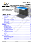
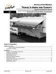
OEM INSTALLATION MANUAL ECLIPSE ARMS AND CANOPY THIS PUBLICATION COVERS MODELS FOR ORIGINAL EQUIPMENT MANUFACTURERS: RV • Universal Eclipse • Eclipse XL • • • Single Switch Multiple Switch Direct Response M an N u or al th C ht w om es tp pl :// P t R im w rin V e w te n w S .n d F up ts w r o p rv om ly f su pp ly .c om These instructions apply to all models listed. Details and procedures unique to a specific model are labeled appropriately. TABLE OF CONTENTS Product Overview .......................................................................................................................... 1 Component Checklist..............................................................................................................................2 Installation ..................................................................................................................................... 4 Required Pre-Installation Preparation.....................................................................................................4 Installing an Awning Rail.........................................................................................................................4 Assembling the Awning ..........................................................................................................................5 Mounting the Awning ..............................................................................................................................6 Electrical ........................................................................................................................................ 8 Single Switch Installation ........................................................................................................................8 Wiring Diagram – Single Switch .....................................................................................................9 Multi-Switch Installation ........................................................................................................................10 Wiring Diagram – Multiple Switch.................................................................................................12 Direct Response Installation .................................................................................................................13 Routing the Wire into the Vehicle .................................................................................................13 Installing the Switches ..................................................................................................................14 Installing the Control Box .............................................................................................................15 Installing the Remote Receiver.....................................................................................................16 Programming the Receiver...........................................................................................................16 Wiring Diagram - Direct Response ...............................................................................................17 Ignition Lockout Sensor Installation (Optional) .............................................................................18 Final Assembly ............................................................................................................................ 19 Attaching the Fascia and Bottom Cover ...............................................................................................19 Securing the Fabric...............................................................................................................................19 Removing the Temporary Assembly Pins.............................................................................................20 Installing the Tractioners.......................................................................................................................20 052547-021r4 Printed in USA September, 2008 PROPRIETARY STATEMENT The Eclipse Patio Awning is a product of Carefree of Colorado, located in Broomfield, Colorado, USA. The information contained in or disclosed in this document is considered proprietary to Carefree of Colorado. Every effort has been made to ensure that the information presented in the document is accurate and complete. However, Carefree of Colorado assumes no liability for errors or for any damages that result from the use of this document. M an N u or al th C ht w om es tp pl :// P t R im w rin V e w te n w S .n d F up ts w r o p rv om ly f su pp ly .c om The information contained in this manual pertains to the current configuration of the models listed on the title page. Earlier model configurations may differ from the information given. Carefree of Colorado reserves the right to cancel, change, alter or add any parts and assemblies, described in this manual, without prior notice. Carefree of Colorado agrees to allow the reproduction of this document for use with Carefree of Colorado products only. Any other reproduction or translation of this document in whole or part is strictly prohibited without prior written approval from Carefree of Colorado. SAFETY INFORMATION WARNING A WARNING INDICATES A POTENTIALLY HAZARDOUS SITUATION WHICH, IF NOT AVOIDED, COULD RESULT IN DEATH OR SERIOUS INJURY AND/OR MAJOR PROPERTY DAMAGE. CAUTION A CAUTION INDICATES A POTENTIALLY HAZARDOUS SITUATION THAT MAY CAUSE MINOR TO MODERATE PERSONAL INJURY AND/OR PROPERTY DAMAGE. IT MAY ALSO BE USED TO ALERT AGAINST UNSAFE PRACTICES. NOTE: A note indicates further information about a product, part, or step. Tip: A tip provides helpful suggestions. Safety Notes: • • • • Always disconnect battery or power source before working on or around the electrical system. Always wear appropriate safety equipment (i.e. goggles). Always use appropriate lifting devices and/or helpers when lifting or holding heavy objects. When using fasteners, use care to not over tighten. Soft materials such as fiberglass and aluminum can be "stripped out" and lose the ability to grip and hold. Reference Publications located @ www.carefreeofcolorado.com:' 052547-001 Eclipse Arms and Canopy After Market Installation Manual 052547-021 Eclipse Arms and Canopy OEM Installation Manual 052547-201 Eclipse Owner's Manual 052547-301 Eclipse Service Manual Carefree of Colorado a Scott Fetzer company 2145 W. 6th Avenue Broomfield, CO 80020 303-469-3324 ♦ www.carefreeofcolorado.com Table of Contents Carefree of Colorado Installation Manual ECLIPSE, OEM PRODUCT OVERVIEW The Eclipse Patio Awning uses unique “scissor” style arms that do not require vertical ground support. The arms provide easy to use pitch adjustment—simply push together the pins on the arms, snap into the hole set desired, and the pitch is set! The pitch can be left in any position and the Eclipse will roll up completely! When the awning is rolled back out, it rolls out to pitch setting previously set. The awning rollbar and arms are made from light weight, no-rust aluminum. The awning fabric is offered in either heavy weight vinyl or the Sunbrella® fabric, one of the most durable, strongest, weather-resistant and fade resistant fabrics on the market. M an N u or al th C ht w om es tp pl :// P t R im w rin V e w te n w S .n d F up ts w r o p rv om ly f su pp ly .c om Eclipse Patio Awning Specifications: Maximum Extension: Maximum Length: Drop @ Min. Pitch: Drop @ Max Pitch: Extend Actuation: Retract Actuation: Position Control: Power Requirements: Circuit Rating: Power Source: Emergency Retract: ECLIPSE UNIVERSAL ECLIPSE XL 8 foot 9 foot 21 feet 21 feet approximately 12 inches approximately 13.5 inches approximately 40 inches approximately 45 inches Gas Shock Gas Shock Motorized roll up Motorized roll up w/ supplemental spring tension Motorized roll out/in 12VDC (operating range 10VDC to 14VDC) 1 20 amp Motor and controls are routed and hardwired into the vehicle’s 12V system Electrical override system (external power source) Eclipse Patio Awning Options: • • • Alumaguard Awning Wrap 2 Uniguard Awning Wrap 2 SunBlocker • • 12V Direct Response Auto-Retract System Remote Control 3 NOTES: 1. Installation with optional SunBlocker shade requires a minimum power source of 12VDC (operating range 12VDC to 14VDC) 2. Selected at time of initial order. 3. Remote Control available with Direct Response installations only 052547-021r4 1 Table of Contents ECLIPSE, OEM Installation Manual Carefree of Colorado COMPONENT CHECKLIST Hardware Rollbar (ordered seperately) 1 2 11 10 4 3 12 13 M an N u or al th C ht w om es tp pl :// P t R im w rin V e w te n w S .n d F up ts w r o p rv om ly f su pp ly .c om Arm Assemblies (see notes 1, 2) 5a 6a 5b Standard 15 XL 7 7 7 7 9 8 9 8 (Single Switch Connector Kit) Electrical (Single Switch) 16 14 6b 17 18 21 19 22 23 20 Electrical (Multi-Switch) 24 25 (Multiple Switch Connector Kit) 26 29 18 19 28 29 30 Carefree of Colorado Electrical (Direct Response) WIND SPEED PATIO RETRACT 31 Carefree of Colorado 12V DIRECT RESPONSE CONTROL BOX PART NO. 060574-003 37 33 32 MODE HI AUTO RETRACT ON MED OFF LOW EXTEND POWER ON Carefree of Colorado PATIO 38 34 Optional Remote Control Kit 40 41 35 36 Optional Ignition Lock-Out Kit 42 43 44 45 46 WIND SPEED MODE AUTO RETRACT ON RETRACT MED POWER ON Carefree of Colorado 39 HI OFF EXTEND LOW Carefree of Colorado (DR Multiple Switch Connector Kit) 47 48 E0012c Optional equipment and electronics are shown but may not be included with a particular arm set. Refer to the original purchase order to determine which options are applicable. 2 052547-021r4 Table of Contents Carefree of Colorado ; ITEM DESCRIPTION ECLIPSE, OEM QTY NOTE Rollbar Assembly 1 Screw, HWHC #6 x 3/8 2 Tractioner 2 3 Screw, Truss Head, SQ Drive #10 x 5/8 2 3 LH Arm Assy, Idler 1 2 RH Arm Assy, Motorized 1 2 LH Arm Assy, Idler, XL only 1 2 RH Arm Assy, Motorized, XL only 1 2 Fascia Assy 2 Bottom Cover w/o switch 1 Bottom Cover w/ switch 1 Screw, Lag 1/4 x 1 1/2 8 Screw, Truss Head, SQ Drive #10 x 5/8 4 Screw, SHC #8 x 3/4 4 Screw, HWHC #6 x 3/8 2 Jumper Cable 1 4 Owner's Manual 1 4 Switch, DPDT, Momentary 1 Switch Plate, Single 1 Spade Connector Female 2 Screw #6 x 1/2 4 Receptacle Single Switch Install 1 5 Receptacle Seal/Cap 1 Spade Connector, Female, Insulated 2 Screw #6 x 1/2 2 Relay Module 1 Switch, DPDT, Latching 1 Switch, DPDT, Momentary 1 Switch Plate, Double 1 Receptacle Multi-Switch Install 1 5 Terminal, Female 5 Screw #6 x 1/2 4 Control Box, Direct Response 1 Screw, Phillips Truss Head #6 x 1/2 2 Harness, Power, Motor 2 Switch, Momentary Contact Patio 1 Switch, Latching, w/o LightWind Speed 1 Switch, Latching, w/ Light Mode 1 Switch Plate, 3 Switch, Patio / Wind Speed / Mode 1 Switch Plate, 2 Switch, Patio / Mode 1 Switch Plate, 1 Switch, Wind Speed 1 Receiver, RF, 433 MHz, RR Version 2 1 Screw, Phillips Truss Head #6 x 1/2 2 Cable 60” 1 Remote Control Key FOB, 433MHz 1 Cable 60” 2 Sensor, Ignition Lock-Out 1 Splitter 1 Receptacle, 9 position Direct Response Multiple Switch 1 5 Screw #6 x 1/2 4 1. Awning configuration is specified at time of order, including awning length, fabric, color and electronics. Check awning assembly against original purchase order. 2. The arm assemblies are configuration specific for the Universal Eclipse and the Eclipse XL and are not interchangeable. 3. Screws and Tractioners are furnished with rollbar assemblies equipped with optional Alumaguard. 4. Place Jumper Cable (item 14) and Owner's Manual (item 15) with RV owner information. Installation manual, if included, is for installer reference. 5. Connector plug is part of the RH arm assembly harness M an N u or al th C ht w om es tp pl :// P t R im w rin V e w te n w S .n d F up ts w r o p rv om ly f su pp ly .c om 1 2 3 4 5A 5B 6A 6b 7 8 9 10 11 12 13 14 15 16 17 18 19 20 21 22 23 24 25 26 27 28 29 30 31 32 33 34 35 36 37 38 39 40 41 42 43 44 45 46 47 48 Notes: Installation Manual 052547-021r4 3 Table of Contents ECLIPSE, OEM Installation Manual Carefree of Colorado INSTALLATION REQUIRED PRE-INSTALLATION PREPARATION 1. Park the vehicle on a flat surface and level the unit. 2. Check where the awning arms will be installed. The arms fit snug to the side of the vehicle and must not cover or interfere with exhaust vents, lights etc. M an N u or al th C ht w om es tp pl :// P t R im w rin V e w te n w S .n d F up ts w r o p rv om ly f su pp ly .c om 3. If there is an awning rail installed, check that the awning rail runs the full length of the awning. Please refer to the note under "Installing an Awning Rail" before proceeding. 4. Refer to the important note on page 6 about the required positioning of the centerline of the roll bar. INSTALLING AN AWNING RAIL NOTE: For canopies WITHOUT Alumaguard or Uniguard: If the vehicle already has a full-length awning rail installed, skip to step 6. For Alumaguard and Uniguard installations: If the existing awning rail is incorporated into the coach trim or a drip rail, it will be necessary to mount a standard awning rail flat on the coach wall. The awning rail and arms must be positioned so that any existing trim does not interfere with the Alumaguard or Uniguard's "Flex Connect" or the awning arm when in the closed position. ALUMAGUARD Hinged w/ Rubber Seal UNIGUARD Flex Connect Must Be Flat When the Awning is Closed Standard Awning Rail Mounted to Coach Wall Standard Awning Rail Mounted to Coach Wall Coach Wall Coach Wall E0050 Figure 1. Fabric Wrap Positioning. 1. Determine the optimum positioning of the awning so that the arms will not interfere with the door frame or light fixtures. The centerline of the rail should be above the door opening a minimum of 6" for vinyl and 7" for Alumaguard/Uniguard. 2. Awning rail must be level. 3. After determining mounting position, mark the position with a chalk line. 4. Seal the back of the rail with silicone sealant or putty tape. 5. Align the awning rail onto the wall and secure with #10 x 3/4” screws. Use all the attach holes in the rail. CAUTION MAKE SURE THE SCREWS ARE SECURELY MOUNTED TO THE STRUCTURAL FRAME OF THE VEHICLE. 6. Use a screwdriver to spread open one end of the awning rail on the installation side. 7. File any sharp edges or burrs from the end of the rail. This will help protect the awning fabric from damage during installation. 8. Spray inside the awning rail track with silicone lubricant. 4 Spread open the end of the awning rail T0012 Figure 2. Adjusting the Awning Rail. 052547-021r4 Table of Contents Carefree of Colorado Installation Manual ECLIPSE, OEM ASSEMBLING THE AWNING If the installation is using an exterior wall mount plug/receptacle, go to step 4. CAUTION THE END CAP WITH THE OUTSIDE SWITCH IS SHIPPED ATTACHED TO THE ARM. USE CARE TO NOT DAMAGE THE SWITCH, ENDCAP OR WIRING DURING INSTALLATION. 1. Decide on the location of the switches and control box to determine the cable routing. If the motor and switch cables are to be routed through the RV wall at the bottom of the arm, no modification is required. Go to step 4. M an N u or al th C ht w om es tp pl :// P t R im w rin V e w te n w S .n d F up ts w r o p rv om ly f su pp ly .c om 2. 3. If the motor and switch cables are to be routed through the RV wall at the top of the arm: 3.1 For units with exterior switch: insert the 3-strand cable (switch cable) into the groove in back of the channel. Allow 5“ of cable to extend from the bottom of the channel. Tie the end cap with switch to the bottom of the channel to avoid damage during installation. 3.2 Remove the plastic wrap at the top of the motorized arm. Partially open the arm being careful to not let the arm extend more than 6”. NOTE: The arm is under tension from the gas shock located in the arm. 3.3 (Refer to Figure 10 page 10) Pull the motor cable out of the hole in the top of the channel. 3.4 For units with exterior switch, insert the switch cable through the hole from the back of the channel. 3.5 Route the excess wire up and out the top of the channel and close the arm. 3.6 Secure the top of the arm in the closed position using a plastic wrap or equivalent. CAUTION DURING ASSEMBLY AND INSTALLATION, THE ARM ASSEMBLIES MUST REMAIN PERPENDICULAR TO THE ROLLER ASSEMBLY. FAILURE TO HANDLE THE ARM ASSEMBLIES CAREFULLY CAN BEND THE DRIVE SHAFT. 4. (Refer to Figure 3) Align the roller assembly with the end cap on the motorized arm assembly. Rotate the end cap until the slot in the cap aligns with the empty slot in the roller assembly, and then press the roller assembly fully into the cap. The end cap must seat squarely over the end of the roller assembly when complete. NOTE: The roller assembly must be oriented with the fabric going over the roller toward the mounting surface. 5. Secure the end cap to the roller assembly using two #10 square-drive screws. 6. For the standard awning, repeat steps 4 through 6 to attach the non-motorized arm assembly to the roller assembly. 7. For the XL awning, insert the spring into the roller assy then rotate the end cap until the slot in the cap aligns with the empty slot in the roller assembly. Finish pressing the roller assembly fully into the cap and secure using two # 10 square drive screws. CAUTION NO PRE-TENSION IS REQUIRED ON THE SPRING. Do not WIND OR TWIST THE SPRING (XL ONLY). #10 x 5/8 Screw (qty: 4) End Cap End Cap Roller Assembly XL ONLY Align Slots Align Slots Figure 3. Assembling the Awning. 052547-021r4 E0020 5 Table of Contents ECLIPSE, OEM Installation Manual Carefree of Colorado MOUNTING THE AWNING CAUTION IT IS RECOMMENDED THAT AT LEAST THREE PEOPLE INSTALL THE AWNING DUE TO ITS SIZE AND WEIGHT. Prior to mounting the awning, it is necessary to mark the first mounting hole. Do not drill at this time. NOTE: For the bottom 3 mounting holes: if mounting into structure, use the 1/4 x 1 1/2 screws; if not attaching into structure, use the furnished moly rivets. M an N u or al th C ht w om es tp pl :// P t R im w rin V e w te n w S .n d F up ts w r o p rv om ly f su pp ly .c om The upper mounting holes must attach into structure using the screws provided. If structural backing is not available for the upper mounting holes, it will be necessary to use the aftermarket arm configuration so that the upper brackets can mount into the structural members at the roof line. 1. Check the location where the awning is to be mounted. Ensure that the awning will not interfere with other equipment on the vehicle, such as a slide out room, light fixtures, exhaust vents etc. 2. On the awning rail, mark the location of the centerline of the motorized arm assembly. From that mark, measure down vertically a distance of 55" (62 1/4” for XL model) ± 1/4" from the centerline of the awning rail. These will be the initial mounting holes. Fabric Width 5” (approx) 5” 6” (approx) (approx) Awning Rail Approximate Drill Area for Upper Cable Routing 6”-7” Clearance from top of door 90o 7 1/2” Typ. 55" 1/4” 62 1/4" 1/4” XL First Mounting Hole (ref) 68 1/4” 75 1/2” XL = Flat Mounting Surface Area 4 1/4” x 70” Approximate Drill Area for Lower Cable Routing Awning Length Centerline of Arm Centerline of Arm E0022a Figure 4. General Layout and Installation. 3. Unroll the canopy one wrap. CAUTION FOR THE XL MODEL, DO NOT UNROLL THE CANOPY MORE THAN 1 TO 1 1/2 WRAPS. NO PRE-TENSION IS REQUIRED ON THE SPRING AT REST (CLOSED). EXCESSIVE UNWRAP WILL CAUSE THE SPRING TO BE PUT IN TENSION AT CLOSE, CAUSING THE AWNING TO NOT CLOSE PROPERLY. 4. With one person holding each arm, the third person should thread the polyrod (the plastic rod on the edge of the fabric) into the awning rail, starting at one end. Carefully move across the vehicle, gently pulling the fabric into the rail, until the awning is in the pre-determined location. NOTE: 5. While the awning fabric is fairly robust, care must be taken not to snag it on the awning rail. (Refer to Figures 4 and 5) Align the first mounting hole in the motorized arm with the location marked in step 2. The arm assembly must be perpendicular to the awning rail. IMPORTANT NOTE: For Uniguard and Alumaguard installations, the centerline of the roll bar must be 3/4" ± 1/4" above the centerline of the awning rail. 6 052547-021r4 Table of Contents Carefree of Colorado Installation Manual ECLIPSE, OEM 6. Drill a 5/32” hole at the first mounting hole and attach the motorized arm using a 1/4 x 1 1/2” lag screw. 7. Confirm that the arm is perpendicular to the awning rail, attach the arm at the second mounting point (shown in Figure 5) using a 5/32” drill bit and a 1/4 x 1-1/2” lag screw. 8. Position the roller assembly so that it is perpendicular to the motorized arm assembly. Position the non-motorized arm perpendicular to the roller assembly. 9. Drill a 5/32” hole at the first mounting hole and attach the non-motorized arm using a 1/4 x 1 1/2” lag screw. M an N u or al th C ht w om es tp pl :// P t R im w rin V e w te n w S .n d F up ts w r o p rv om ly f su pp ly .c om 10. Check the alignment; the arm assembly must be perpendicular to the roller assembly. When the alignment is correct, drill and attach the arm at the second mounting hole (shown in Figure 4) using a 5/32” drill bit and a 1/4 x 1-1/2” lag screw. 11. Hold the awning closed and carefully remove the plastic wraps at the top of the arms. The awning will open a few inches. 12. Cap or cover the exposed ends of the motor wires. This is to prevent accidental shorting or grounding during assembly. 13. Open the awning about 18” or until the top mounting holes on the arms are visible. To open • Use the supplied jumper cables and attach to the emergency terminals located on the top of the motorized head. • Connect the other ends of the jumper leads to a 12V source. If the awning does not begin to move, reverse the leads. 14. Using a 5/32” drill bit, locate and drill the mounting holes. 15. Using two each 1/4 x 1-1/2” lag screws, attach the top of the arm assemblies to the vehicle. 052547-021r4 Mounting Holes 1/4 x 1 1/2 Screws Only Upper Mounting Holes (Arm Extended Out) 1st Mounting Hole 1/4 x 1 1/2 Screws or 3/16 Moly Rivets 2nd Mounting Hole Lower Mounting Holes E0003 Figure 5. Arm Mounting Hole Locations. 7 Table of Contents ECLIPSE, OEM Installation Manual Carefree of Colorado ELECTRICAL The Eclipse Patio Awning has three switch/wiring options. The single switch configuration has one interior extend/retract switch. The multiple switch configuration has one power switch, one exterior extend/retract switch, one interior extend/retract switch and a control box. The multiple switch wiring instructions start on page 10. The Direct Response Auto-Retract system is described on page 13. • Failure to follow the wiring instructions in this publication may void the motor warranty. • All wiring must conform to NEC (National Electrical Code) and local codes. • DO NOT wire two or more motors to one switch—No parallel wiring. M an N u or al th C ht w om es tp pl :// P t R im w rin V e w te n w S .n d F up ts w r o p rv om ly f su pp ly .c om NOTES: CAUTION ALWAYS DISCONNECT THE VEHICLE BATTERY AND ELECTRICAL SOURCES BEFORE WORKING WITH THE ELECTRICAL WIRING AND COMPONENTS. SINGLE SWITCH INSTALLATION 1. Determine the final location of the switch and mark the location. NOTE: 2. 3. 5/16" Hole Thru Existing Slots Motor Cable The switch panel must be mounted within 32 inches of the point of entry for the cable. Top of Channel Routing For installations using the cable with a direct connection (no external plug) 2.1 (Refer to Figure 6) Drill a 5/16” hole through the vehicle wall for the motor cable. 2.2 Route the cable through the holes to the location of the switch panel. 2.3 Seal the cable and hole using a silicone sealant. 2.4 Go to step 4. For installations using an external wall mount plug/receptacle: 3.1 Drill a 15/16” hole through the exterior wall in the location shown in Figure 7. Adjust the location within the area to avoid structure, cabinetry etc. 3.2 Using a 2-wire cable, terminate the wire ends with the female terminals provided. 3.3 Pull the terminated wires out through the hole. 3.4 Slide the rubber seal/connector cover onto the back of the receptacle. 3.5 (Refer to Figure 9, Detail A) Attach terminated wires to the back of the receptacle. 3.6 Secure the receptacle using two (2) #6 x 1/2 screws. 5/16" Hole 1 1/2" Motor Cable Bottom of Channel Routing E0005 Figure 6. Cable Pass Thru Drill Pattern. 3" 5" Drill Area for Wall Mount Receptacle 1" 4" E0033 Figure 7. Drill Location for Receptacle. 4. At the switch panel location, use a 2 1/4” hole saw and cut a hole. 5. Route the cable through the hole and terminate the wires with spade connectors. 6. Push the switch into the faceplate until the locking tabs click into place behind the faceplate. 7. (Refer to Figure 9) Connect the wires from step 9 to the switch as shown. 8 052547-021r4 Table of Contents Carefree of Colorado 8. Installation Manual ECLIPSE, OEM Run a 12 gauge wire (never use less than 14 gauge) from the power distribution panel (auxiliary battery circuit) or equivalent. The circuit should be protected by a 20 amp fuse. 2 1/4" NOTE: Minimum wire length and Locking Tabs maximum wire size should be selected to assure adequate voltage. Run a wire to chassis ground. Suitable ground would be the vehicle chassis or conductive structure connected to the chassis. 2 3/4" (min.) Covered Terminals on Bottom 2 3/4" (typ.) M an N u or al th C ht w om es tp pl :// P t R im w rin V e w te n w S .n d F up ts w r o p rv om ly f su pp ly .c om 9. E0010 10. (Refer to Figure 9) Route the two new wires through the hole and terminate with spade connectors. Connect to the control switch. Figure 8. Single Switch Plate Assembly. 11. Carefully push the wires and switch into the mounting hole, then attach the switch plate assembly using four (4) #6 x 1/2” screws. 12. Restore vehicle power and test the awning operation. Wiring Diagram – Single Switch Wall 32” A 1 1 Black Carefree of Colorado 6 3 5B 2B 4 1 Front View of Switch Panel Rear View of Switch Panel Ground Red Black 1 Red Black N L N L Red +12VDC NOTE: 1 Wire color from the motor may deviate on some models. Standard Color Red Black Detail A Optional Wall Mount Connector Deviation Color Yellow Brown E0008 Figure 9. Single Switch Wiring Diagram. WARNING TERMINALS 1 AND 4 ARE CAPPED WITH FULLY INSULATED CONNECTORS. THESE TERMINALS MUST REMAIN CAPPED AT ALL TIMES. 052547-021r4 9 Table of Contents ECLIPSE, OEM Installation Manual Carefree of Colorado MULTI-SWITCH INSTALLATION 1. Determine the final layout of the switches and the control box and mark the locations. NOTE: For installations using the cables with direct 5/16" Hole connections (no external plug): Thru Existing Slots 2.1 (Refer to Figure 10) Drill two 5/16” holes through the vehicle wall for the motor cable Motor Cable External and exterior switch cable. Move the cables Switch Cable out of the way to avoid damage while drilling. Top of Channel Routing 2.2 Route the cables through the holes to the location of the relay module. 2.3 Seal the cables and holes using a silicone sealant. 5/16" Hole 2.4 Go to step 4. 1 1/2" M an N u or al th C ht w om es tp pl :// P t R im w rin V e w te n w S .n d F up ts w r o p rv om ly f su pp ly .c om 2. When using only the wire harnesses furnished, the maximum distance from the cable point of entry to the relay module is 48”. Maximum distance from the relay module to the switches is 16”. 3. 4. 5. For installations using an external wall mount plug/receptacle: 3.1 Drill a 7/8” hole through the exterior wall in the location shown in Figure 11. Adjust the location within the area to avoid structure, cabinetry etc. 3.2 Using a 3-wire cable and a 2-wire cable, terminate the wire ends with the female terminals provided. 3.3 Pull the terminated wires out through the hole. 3.4 (Refer to Figure 13, Detail A) Insert the terminated wire ends into the back of the receptacle. 3.5 Coat the backside of the receptacle flange with silicone sealant and insert the receptacle into the hole. 3.6 Secure the receptacle using 4 #6 x 1/2 screws. (Refer to Figure 12) At the switch panel location, use a 2 1/4” hole saw and cut 2 holes 1 1/2” apart. E0004 Figure 10. Cable Pass Thru Drill Pattern. Figure 11. Drill Location for Receptacle. Separate the wires from the relay module into 3 groups: • Brown, yellow and gray with spade terminals (interior switch), • Black and red with spade terminals (interior power switch), • Connector bundle with: Brown, yellow and gray (exterior switch), and Blue and white (motor). NOTE: 10 External Switch Cable Motor Cable Bottom of Channel Routing The relay module harness is supplied with one connector installed. The installer must furnish the mating connector (p/n 1-480704) and terminals (p/n 350547-3) for the exterior switch and motor cables. Vendor: AMP/Tyco Electronics. 052547-021r4 Table of Contents Carefree of Colorado 6. ECLIPSE, OEM Measure and cut away any excess cable from the motor and exterior switch cables. Terminate the wires and install in the mating connector as shown in Figure 13 page 12. NOTE: 7. Installation Manual As an alternate installation, cutoff the existing connector from the control box bundle and butt splice the cable wires and relay module wires as shown in Detail A on page 10. Route the remaining wires, from the relay module, through the double hole. 1 1/2" M an N u or al th C ht w om es tp pl :// P t R im w rin V e w te n w S .n d F up ts w r o p rv om ly f su pp ly .c om O 2 1/4" Locking Tab 2 3/4" 2 3/4" (min.) 4 1/4" E0011 Figure 12. Double Switch Plate Assembly. 8. Push the switches into the face plate until the locking tabs click into place behind the face plate. NOTE: 9. For the unit to operate correctly, the switches must be located and oriented as shown. The power switch is a double throw, latching switch. The extend/retract switch is a double throw, momentary contact switch. Connect the wires from step 7 to the switches as shown in Figure 13 page 12. 10. Run a 12 gauge wire (never use less than 14 gauge) from the power distribution panel (auxiliary battery circuit) or equivalent. The circuit should be protected by a 20 amp fuse. NOTE: Minimum wire length and maximum wire size should be selected to assure adequate voltage. 11. Run a wire to chassis ground. Suitable ground would be the vehicle chassis or conductive structure connected to the chassis. 12. (Refer to Figure 13, page 12) Route the two new wires through the hole and terminate with spade connectors. Connect to the power switch. 13. Carefully push the wires and switches into the mounting hole and attach the switch plate assembly using 4 #6 x 1/2” screws. 14. Remove the paper backing from the adhesive foam on the relay module and press on a flat surface in the proximity of the switches. 15. Restore vehicle power and test the awning operation. 052547-021r4 11 Table of Contents ECLIPSE, OEM Installation Manual Carefree of Colorado Vehicle Wall Wiring Diagram – Multiple Switch Gray Yellow Brown Gray Eclipse Exterior Switch Relay Module Rear View of Connectors Shown Exterior Switch Brown Yellow 6 6 5 2 2 5 4 1 1 4 Gray Brown Yellow 1 Blue White Gray Brown Yellow Gray Brown Yellow Red Black Blue White Brown Yellow A B Gray Red Butt Splice (5 plcs) Black M an N u or al th C ht w om es tp pl :// P t R im w rin V e w te n w S .n d F up ts w r o p rv om ly f su pp ly .c om Red Black Motor 7 Detail A Alternate Wire Connection 6 5 2 1 3 1 Carefree of Colorado 1 Motor Front View of Switch Panel Rear View of Connectors Shown Red Red Black Black 2 Gray 3 7 Yellow Brown 1 5 6 1 2 6 7 3 5 Exterior Detail B Switch Optional Wall Mount Connector Gray Yellow Brown +12VDC Vehicle Ground Rear View of Switch Panel NOTE: 1 Wire color from the motor may deviate on some models. Standard Color Red Black Deviation Color Yellow Brown E0032a Figure 13. Eclipse Multi-Switch Wiring Diagram. 12 052547-021r4 Table of Contents Carefree of Colorado Installation Manual ECLIPSE, OEM DIRECT RESPONSE INSTALLATION Routing the Wire into the Vehicle 1. Determine the final layout of the switches and the control box and mark the locations. M an N u or al th C ht w om es tp pl :// P t R im w rin V e w te n w S .n d F up ts w r o p rv om ly f su pp ly .c om 1/4" Hole 2. For installations using the cables with direct connections (no external plug): 5/16" Hole Thru Slot 5/16" Hole 2.1 (Refer to Figure 14) Drill two 5/16” holes Thru Slot through the vehicle wall for the motor cable and exterior switch cable. Move the cables out of Motor Cable the way to avoid damage while drilling. External Switch Cable 2.2 Drill a 1/4" hole for the sensor cable. Sensor Cable 2.3 Cut off the existing connector on the sensor cable then route the wires and cable through the Top of Channel Routing holes to the location of the control box. 2.4 Seal the cables and holes using a silicone sealant. 3. For installations using an external wall mount Sensor Cable plug/receptacle: 3.1 Drill a 1 1/8” hole through the exterior wall in the 1/4" Hole location shown in Figure 15. Adjust the location 1 1/2" 5/16" Hole within the area to avoid structure, cabinetry etc. 3.2 From inside the vehicle, route a 3-wire cable External (exterior switch) and a 2-wire cable (motor) from Motor Cable Switch Cable the control box location to the hole made in the step above. Terminate the wire ends with the female terminals provided. Bottom of Channel Routing E0004a 3.3 Route a RJ11 cable from the control box Figure 14. Cable Pass Thru Drill Pattern. location to the hole made above. 3.3 Pull the terminated wires and cable out through the hole. 3.4 (Refer to page 17, Detail A) Insert the terminated wire ends into the back of the receptacle as shown. Attach the RJ11 cable. 3.5 Coat the backside of the receptacle flange with silicone sealant and insert the receptacle and wires into the hole. 3.6 Secure the receptacle using four (4) #6 x 1/2 screws. Figure 15. Drill Location for Receptacle. 052547-021r4 13 Table of Contents ECLIPSE, OEM Installation Manual Carefree of Colorado Installing the Switches 1. At the switch panel location(s), use a 2 1/4” hole saw and cut one hole for each switch. The center of each hole is 1 1/2” apart for switches mounted in the same panel. 2. Each switch assembly is labeled. Carefully push the connector and wires through the switch panel then push the switch into the faceplate until the locking tabs click into place behind the faceplate. • The momentary switch is the “Patio” switch; • The latching switch w/o light is the “Wind Speed” switch; • The latching switch w/ light is the “Mode” switch. M an N u or al th C ht w om es tp pl :// P t R im w rin V e w te n w S .n d F up ts w r o p rv om ly f su pp ly .c om CAUTION ENSURE THAT THE SWITCH LABELS MATCH THE FACEPLATE LABELS FOR THE SWITCH IDENTIFICATION AND ORIENTATION! THE SQUARE LENS ON THE SWITCH MUST BE AT THE BOTTOM. NOTE: If it is necessary to remove the switch from the panel, press and hold the locking tabs on the switch then carefully work the switch out of the panel. Do not try to force the switch, it is possible to break the locking tabs. 3. When all switches are mounted into the faceplate(s), carefully push the connectors, wires and switches through the mounting holes drilled in step 1. 4. Hold the faceplate(s) in position and secure to the mounting surface using four (4) #6 x 1/2 screws. Tip: Drilling a small pilot hole for the screws will reduce the chance of splitting or stripping out the hole with the screws. 1 1/2” O 2 1/4” 1 1/2” 1 1/2” O 2 1/4” O 2 1/4” Locking Tab (ref) 2 3/4” 2 3/4” 5 3/4” #6 x 1/2 Screw (typ.) Patio / Sensitivity / Mode Switches Single Plate 2 3/4” 2 3/4” 2 3/4” 2 3/4” 4 1/4” Patio / Mode Switches Multiple Plate 2 3/4” Sensitivity Switch WS002 Figure 16. Mounting the Switches. 14 052547-021r4 Table of Contents Carefree of Colorado Installation Manual ECLIPSE, OEM Installing the Control Box #6 x 1/2 Screw (2 plcs) Carefree of Colorado 12V DIRECT RESPONSE CONTROL BOX PART NO. 060574-003 3 1/8” 5 1/4” 2” M an N u or al th C ht w om es tp pl :// P t R im w rin V e w te n w S .n d F up ts w r o p rv om ly f su pp ly .c om DR008 1. Position the control box and secure using two (2) #6 x 1/2” screws. 2. Attach the switch harness connectors to the box at the positions labeled on the box. Press the connectors in until the tabs click into place to ensure a solid connection. 3. For installations with an exterior switch and/or additional patio switch: Splice the wires from the secondary switch in parallel with the main PATIO switch wires. Pin 1 of the additional switch should go to pin 1 of the main patio switch etc. 4. For direct connection installations: Use a 4-conductor modular plug crimp tool to install a new RJ-11 4-conductor plug to replace the connector removed previously. THE CABLE AND PLUG MUST BE ORIENTED AS SHOWN FOR PROPER SYSTEM OPERATION. Yellow Black 5. Connect the cable from the Direct Response sensor to the control box. 6. Connect a two-wire harness to the control box in the position marked MOTOR. 7. Run the motor wire cable from the awning to the control box. Splice the wires to the harness in step 6. The red wire should go to Pin marked “A” and the black goes to the pin marked “B”. NOTE: During testing, it may be necessary to reverse these wires (red to B, black to A) if the awning extend and retract functions are reversed. 8. Connect power to the control box; 8.1 Run a 12 gauge wire (never use less than 14 gauge) from the power distribution panel (auxiliary battery circuit) or equivalent. 8.2 Run a wire to chassis ground. Suitable ground would be the vehicle chassis or conductive structure connected to the chassis. 8.3 Connect a two-wire harness to the control box in the position marked +12V/GROUND. 8.4 Splice the wires from steps 2 and 3 to the harness. Carefully note the labeling on the box so that the 12V power goes to the 12V pin and the ground goes to the pin labeled ground. 052547-021r4 RJ-11 Plug DR007 15 Table of Contents ECLIPSE, OEM Installation Manual Carefree of Colorado Installing the Remote Receiver Determine the location of the optional RF receiver: 1.1 Do not mount the unit near heat producing elements such as LP appliances or engine Screw, Truss Head exhaust components. 4 3/16” #6 x 1/2 (qty: 2) 1.2 For best reception, do not mount the unit near or on a metal surface. 1.3 Mount the unit with the antenna pointing up. 3 7/8” 1” 1.4 The included cable is approximately 60 inches DR022 long. Mount the unit close enough to the control Figure 17. Mounting the RF Reciever. box so that the cord can be connected without stressing the connections. 1.5 Allow room below the box to access the connector jack, programming button and indicator light. Position the control box and secure using two (2) #6 x 1/2” screws. NOTE: If the box is mounted on a surface that is less that 1/2” thick, the screws will protrude through the opposite side of the surface. Connect the cable to the receiver. If using the Ignition Lockout Sensor, route the cable to the splitter and connect. If not using the sensor connect the cable directly to the control box M an N u or al th C ht w om es tp pl :// P t R im w rin V e w te n w S .n d F up ts w r o p rv om ly f su pp ly .c om 1. 2. 3. 4. Programming the Receiver These instructions apply to the current 433 MHz configuration of the remote and receiver. For older versions (418 MHz) refer to the Eclipse Service Manual. 1. Power to the control box must be on. NOTE: Pressing the stop button will cause the blue Stop up arrow button to default as the close (retract) function. If a function button is pressed to train the receiver, it will be programmed as the close (retract) button. Example: Pressing the bottom button will program the bottom button for retract and the top button as extend. 4. Repeat for each additional remote. Indicator Light Press to Learn Transmitter TO EYE PORT on RP24 3. Press and release the stop button on the remote. The red light will go out after the receiver learns the remote signal. Program Mode 2. Press and release the “Press to Learn Transmitter” button on the bottom of the receiver box. The receiver is in program mode when the red light comes on. UP Program Button DR020 OPERATIONAL NOTES: • Transmitter and receiver operate on a frequency of 433 MHz. • The receiver exits the program mode after ten seconds. • If the light does not come on above, the memory is full and must be cleared. If the light still does not come on, check the continuity of the cord between the boxes and repair or replace as required. Pin 1 of the 1st connector goes to pin 1 of the 2nd connector etc. • If the light does not go out in above, the receiver already knows the transmitter's signal or the battery in the remote needs to be replaced. • To clear the memory: PRESS AND HOLD the transmitter learn button. While holding the button, the indicator light should be OFF for the full 5 seconds then come on. • The system may be programmed for up to 5 remotes. Additional remotes may be ordered separately. 16 052547-021r4 Table of Contents Carefree of Colorado Installation Manual ECLIPSE, OEM Wiring Diagram - Direct Response Ignition Switched +12VDC Press to Learn Transmitter Program Mode M an N u or al th C ht w om es tp pl :// P t R im w rin V e w te n w S .n d F up ts w r o p rv om ly f su pp ly .c om 12VDC Ground RF Reciever TO EYE PORT on RP24 Ignition Lockout Sensor (Optional) 2 UP Splitter 1 Mode Switch BLACK 1 3 5 7 2 4 6 8 9 10 BLUE RED GROUND POWER ON DIR. RES. ON +12VDC GRN BLK OR RED COM 5 LOW 7 Wind Speed Switch Carefree of Colorado 12V DIRECT RESPONSE CONTROL BOX PART NO. 060574-003 14 15 16 GRAY YELLOW BRN 13 12 11 +12VDC Ground B A EXT 1 COM 3 RET 5 6 7 8 1 2 M HI 1 Control Box RED BLACK 7 Patio Switch EXT 1 COM 3 RET Motion Sensor 7 Additional Patio Switch BROWN YELLOW GRAY Exterior Switch Vehicle Wall A DR005a Figure 18. Direct Response Wiring Diagram. 052547-021r4 17 Table of Contents ECLIPSE, OEM Installation Manual Carefree of Colorado Green Red Black BROWN YELLOW GRAY From Exterior Switch Rear View of Connectors Shown 3 2 1 RED 5 BLACK 6 From Motor BROWN YELLOW GRAY To Patio Switch Connector 3 2 1 2 3 6 5 4 4 5 6 9 8 7 7 8 9 1 Yellow Green Red Black 1 2 3 5 6 RED BLACK To Control Box Yellow Cables are 4-wire RJ11 terminated phone cord (straight, no twist). M an N u or al th C ht w om es tp pl :// P t R im w rin V e w te n w S .n d F up ts w r o p rv om ly f su pp ly .c om From Sensor To Motor Connector Phone Cable Phone Cable Detail A Optional Wall Mount Connector 1 2 Detail B Phone Cable DR005b Splitter is used only when the optional Lock-Out Sensor is installed. Connect the RF receiver directly to the control box if Lock-Out is not installed. The optional Lock-Out Sensor can be used only with control boxes marked "060574-003". Wires for the sensor are not pin specific. Ignition Lockout Sensor Installation (Optional) The optional STD ignition lockout will disable the extend function when the module receives a current through a switched 12VDC circuit. A switched 12VDC source is a line that is "hot" when the ignition switch is in the on position; or, a 12VDC circuit through a relay that is "hot" when a specific condition is met (i.e. releasing the parking brake). Relays are furnished by the installer. (Refer to the wiring diagram on page 17) 1. Disconnect power to the awning. Disconnect the battery or pull the appropriate circuit breaker. 2. Locate the control box for the Direct Response System. NOTE: The 6" cable and splitter are for systems with a remote. If there is no remote, attach the 60" cable to the module; plug the other end of cable directly to the "RR24" port in the control box. Then proceed with step 8. 3. If there is a remote receiver, disconnect the cable from the "RR24" port in the control box. Do not disconnect the cable from the receiver box. 4. Connect the supplied 6" cable to “RR24” port in the control box. 5. Attach the splitter to the other end of the cable. 6. Plug the cable from the remote receiver into the splitter. 7. Attach the Lock-Out Sensor to the end of the 60" cable. Route the cable as desired and connect the cable to the splitter. NOTE: Wires to the module are not pin specific. 8. Attach one 18-gauge wire to a terminal of the sensor and route the wire to a suitable 12VDC ground. 9. Attach a second 18-gauge wire to the second terminal of the sensor and route the wire to a SWITCHED 12VDC source. 10. Bundle and secure the sensor, cable and wires as required. 18 052547-021r4 Table of Contents Carefree of Colorado Installation Manual ECLIPSE, OEM FINAL ASSEMBLY ATTACHING THE FASCIA AND BOTTOM COVER 1. Make sure the awning is completely closed. 2. Insert the tab, on the fascia, under the arm base and rest it on the mounting plate. 3. Check that the gap between the top of the fascia and the arm channel is approximately 1/8". Facia M an N u or al th C ht w om es tp pl :// P t R im w rin V e w te n w S .n d F up ts w r o p rv om ly f su pp ly .c om • Facia Tab 4. If the gap is too large or too small, set the fascia aside, loosen the mounting plate screws and adjust the mounting plate height as required. Tighten the screws and set the fascia in position. Place the bottom cover beneath fascia. Carefully tuck any wires into the bottom cover. NOTE: 5. Mounting Plate Screws Seat Facia in Groove There are tabs on the top of the cover to correctly align the bottom cover and fascia. The fascia should seat in the groove of the cover. Mounting Plate Alignment Tabs Bottom Cover #8 x 3/4 Socket Head Cap Screw Attach the cover to the fascia with the supplied socket head screws using a 9/64” Allen wrench. The bolts must go through the cover, the plate, and the fascia. E0015 Figure 19. Attaching the Fascia and Bottom Cover. 6. Repeat for the other side. 7. Verify proper installation by opening and closing the awning. SECURING THE FABRIC 1. 2. Roll the awning in and out several times to make sure that the fabric is square on the rollbar. Secure the canopy using one, #6 x 3/8" hex head screw at both sides of the awning. Awning Rail Fabric 1" Polyrod #6 x 3/8 Screw Awning Rail Soft Connect Uniguard 1" Polyrod #6 x 3/8 Screw Fabric Awning Rail Alumaguard #6 x 3/8 Screw E0014 Figure 20. Securing the Fabric. 2.1 For vinyl awnings, place screw through awning rail, polyrod and canopy approximately 1” in from the end of the fabric. 2.2 For Uniguard awnings, place screw through awning rail, polyrod and the soft connect material approximately 1" in from the end of the fabric. 2.3 For Alumaguard awnings, place screw on the outer edge of the Alumaguard (not through the Alumaguard). 052547-021r4 19 Table of Contents ECLIPSE, OEM Installation Manual Carefree of Colorado REMOVING THE TEMPORARY ASSEMBLY PINS 2 pins are inserted into the back of the left (idler) head for lateral stability during installation. Using a pair of pliers, remove and discard both pins. NOTE: The awning will operate with the pins in place; for long term use, the pins must be removed to allow for climate variances. Figure 21. Removing the Assembly Pins. M an N u or al th C ht w om es tp pl :// P t R im w rin V e w te n w S .n d F up ts w r o p rv om ly f su pp ly .c om INSTALLING THE TRACTIONERS The tractioners are used with the alumaguard metal fabric wrap and vinyl fabrics with uniguard. Keeper 1/4" Gap A Alumaguard or Uniguard Place Screw Between Slots on Roller Position Tractioner under Alumaguard/Uniguard View A-A (Alumaguard) 1/4" Gap A Place Screw Between Slots View A-A on Roller (Uniguard w/ Vinyl Fabric) E0058 Figure 22. Installing the Alumaguard Tractioner. 1. 2. 3. 7. Partially extend the awning until the Alumaguard/Uniguard is extended as shown. Unlock the keeper and wrap the tractioner around the roller tube. Position the tractioner under the Alumaguard/Uniguard with a 1/4” gap between Alumaguard and tractioner. Lock the keeper. Repeat for the other end of the rollbar. Extend the awning to verify that the tractioners are lifting the metal wrap up and over the roller assembly. To secure the tractioner, drill a 1/8” hole through the tractioner and rollbar, roughly center the hole between two slots of the rollbar. Secure with one (1) #10 square drive screw. 20 052547-021r4 4. 5. 6. Table of Contents This Manual is Compliments of Northwest RV Supply 86325 College View Road Eugene, OR 97405 Local: 541-746-9092 Toll-Free: 866-678-7467 Fax: 541-736-5573 http://www.nwrvsupply.com [email protected] Northwest RV Supply carries a large spectrum of surplus, used, and new RV parts and components. Please feel free to visit our website for additional information.