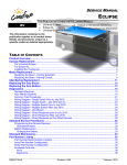
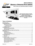
1
INSTALLATION MANUAL ECLIPSE ARMS UPGRADE FOR ONE-TOUCH RV THIS PUBLICATION COVERS THE FOLLOWING MODELS: • Universal Eclipse (8 foot extension) • Eclipse XL (9 foot extension) These instructions apply to all models listed. Details and procedures unique to a specific model are labeled appropriately. TABLE OF CONTENTS Product Overview .......................................................................................................................... 1 Eclipse Patio Awning Specifications:..............................................................................................1 Eclipse Patio Awning Options: .......................................................................................................1 Component Checklist..............................................................................................................................2 Installation ..................................................................................................................................... 3 Required Pre-Installation Preparation.....................................................................................................3 Mounting the Arms..................................................................................................................................4 Installation – Electrical.................................................................................................................. 6 Final Assembly .............................................................................................................................. 7 Attaching the Fascia and Bottom Cover .................................................................................................7 Securing the Fabric.................................................................................................................................7 Removing the Temporary Assembly Pins...............................................................................................8 Installing the Tractioners.........................................................................................................................8 052547-101r1 Printed in USA February, 2007 PROPRIETARY STATEMENT The Eclipse Patio Awning is a product of Carefree of Colorado, located in Broomfield, Colorado, USA. The information contained in or disclosed in this document is considered proprietary to Carefree of Colorado. Every effort has been made to ensure that the information presented in the document is accurate and complete. However, Carefree of Colorado assumes no liability for errors or for any damages that result from the use of this document. The information contained in this manual pertains to the current configuration of the models listed on the title page. Earlier model configurations may differ from the information given. Carefree of Colorado reserves the right to cancel, change, alter or add any parts and assemblies, described in this manual, without prior notice. Carefree of Colorado agrees to allow the reproduction of this document for use with Carefree of Colorado products only. Any other reproduction or translation of this document in whole or part is strictly prohibited without prior written approval from Carefree of Colorado. SAFETY INFORMATION WARNING A WARNING INDICATES A POTENTIALLY HAZARDOUS SITUATION WHICH, IF NOT AVOIDED, COULD RESULT IN DEATH OR SERIOUS INJURY AND/OR MAJOR PROPERTY DAMAGE. CAUTION A CAUTION INDICATES A POTENTIALLY HAZARDOUS SITUATION THAT MAY CAUSE MINOR TO MODERATE PERSONAL INJURY AND/OR PROPERTY DAMAGE. IT MAY ALSO BE USED TO ALERT AGAINST UNSAFE PRACTICES. NOTE: A note indicates further information about a product, part, or step. Tip: A tip provides helpful suggestions. Safety Notes: • • • • Always disconnect battery or power source before working on or around the electrical system. Always wear appropriate safety equipment (i.e. goggles). Always use appropriate lifting devices and/or helpers when lifting or holding heavy objects. When using fasteners, use care to not over tighten. Soft materials such as fiberglass and aluminum can be "stripped out" and lose the ability to grip and hold. Reference Publications located @ www.carefreeofcolorado.com:' 052547-001 Eclipse Arms and Canopy After Market Installation Manual 052547-021 Eclipse Arms and Canopy OEM Installation Manual 052547-101 Eclipse Arms Upgrade for One-Touch 052547-201 Eclipse Owner's Manual 052547-301 Eclipse Service Manual 052987-002 WindSmart Installation & Operation Manual 052526-001 Direct Response Installation & Operation Manual Carefree of Colorado a Scott Fetzer company 2145 W. 6th Avenue Broomfield, CO 80020 303-469-3324 ♦ www.carefreeofcolorado.com Table of Contents Carefree of Colorado Installation Manual ECLIPSE ARM UPGRADE PRODUCT OVERVIEW The Eclipse Patio Awning uses unique “scissor” style arms that do not require vertical ground support. The arms provide easy to use pitch adjustment—simply push together the pins on the arms, snap into the hole set desired, and the pitch is set! The pitch can be left in any position and the Eclipse will roll up completely! When the awning is rolled back out, it rolls out to pitch setting previously set. The awning rollbar and arms are made from light weight, no-rust aluminum. The awning fabric is offered in either heavy weight vinyl or the Sunbrella® fabric, one of the most durable, strongest, weather-resistant and fade resistant fabrics on the market. Eclipse Patio Awning Specifications: Maximum Extension: Maximum Length: Drop @ Min. Pitch: Drop @ Max Pitch: Extend Actuation: Retract Actuation: Position Control: Power Requirements: Circuit Rating: Power Source: Emergency Retract: ECLIPSE UNIVERSAL ECLIPSE XL 8 foot 9 foot 21 feet 21 feet approximately 12 inches approximately 13.5 inches approximately 40 inches approximately 45 inches Gas Shock Gas Shock Motorized roll up Motorized roll up w/ supplemental spring tension Motorized roll out/in 12VDC (operating range 10VDC to 14VDC) 1 20 amp Motor and controls are routed and hardwired into the vehicle’s 12V system Electrical override system (external power source) Eclipse Patio Awning Options: • • • Alumaguard Awning Wrap 3 Uniguard Awning Wrap 3 SunBlocker • • • WindSmart Auto-Retract System 4 Remote Control 5 12V Direct Response Auto-Retract System 4 NOTES: 1. Installation with optional SunBlocker shade requires a minimum power source of 12VDC (operating range 12VDC to 14VDC) 2. Charge time is approximate requirement for a fully discharged battery to be fully charged. 3. Selected at time of initial order. 4. Remote Control available with auto-retract installations only 052547-101r1 1 Table of Contents ECLIPSE ARM UPGRADE Installation Manual Carefree of Colorado COMPONENT CHECKLIST Hardware Arm Assemblies (see notes 1, 2) 5 1a 2a 1b Standard 6 7 8 9 2b XL 11 3 4 1. 2. 3. 2 12 3 3 3 4 4 Electrical 13 14 15 16 4 ; ITEM DESCRIPTION 1A LH Arm Assy, Idler 1B RH Arm Assy, Motorized 2A LH Arm Assy, Idler, XL only 2b RH Arm Assy, Motorized, XL only 3 Fascia Assy 4 Bottom Cover w/o switch 5 Screw, Lag 6 Screw, Lag 7 Rivet, Moly 8 Screw, Truss Head, SQ Drive 9 Screw, SHC 10 Screw, HWHC 11 Jumper Cable 12 Owner's Manual 13 Switch, DPDT, Momentary 14 Switch Plate, Single 15 Spade Connector Female 16 Screw Notes: 10 E0012d 1/4 x 2 1/2 1/4 x 1 1/2 3/16 #10 x 5/8 #8 x 3/4 #6 x 3/8 #6 x 1/2 QTY NOTE 1 2 1 2 1 2 1 2 2 1 8 8 4 4 4 2 1 3 1 3 1 1 2 4 Awning configuration is specified at time of order, including awning length, fabric, color etc. Check awning assembly against original purchase order. The arm assemblies are configuration specific for the Universal Eclipse and the Eclipse XL and are not interchangeable. Place Jumper Cable (item 18) and Owner's Manual (item 19) with RV owner information. Installation manual, if included, is for installer reference. 052547-101r1 Table of Contents Carefree of Colorado Installation Manual ECLIPSE ARM UPGRADE INSTALLATION REQUIRED PRE-INSTALLATION PREPARATION 1. Park the vehicle on a flat surface and level the unit. 2. Check where the awning arms will be installed. The arms fit snug to the side of the vehicle and must not cover or interfere with exhaust vents, lights etc. 3. Refer to the important note on page 4 about the required positioning of the centerline of the roll bar. 4. Determine the existing wiring configuration: • Configuration A – Direct connection to switch. Motor wires connect directly to switch through the wall-mount connector. Will be able to use existing hardwired single switch with Eclipse. • Configuration B – Control box electronics. A control box is installed between the connector and switches. Disconnect and remove the existing control boxes, wiring and switches. The system is replaced with the single switch control. • Configuration C – WindSmart. An optional WindSmart controller is installed. Disconnect and replace the existing control box. Reference the WindSmart installation manual for wiring. It will be necessary to order the new control box separately. The control boxes are not interchangeable! • Configuration D – Arm mounted motion sensor and auto-retract. Disconnect and remove the existing control boxes, wiring and switches. It will be necessary to replace the controls with the single switch configuration; or, for auto-retract options, use the Eclipse WindSmart upgrade kit (SR0023) or the Eclipse Direct Response upgrade kit (SR0036). Both systems require running an additional wire from outside to inside the vehicle. 5. Remove the fabric retaining screws from the awning rail. It may be necessary to adjust the fabric position after the arms are installed. 6. If Alumaguard is installed, temporarily remove the tractioners from the roll bar. These must be will be reinstalled after the new arms are installed. 7. Determine if a new awning rail is required. • For canopies WITHOUT Alumaguard or Uniguard: If the existing awning rail is incorporated into the coach trim or a drip rail, it will be necessary to mount a standard awning rail flat on the coach wall. The awning rail and arms must be positioned so that any existing trim does not interfere with the awning arm when in the closed position. • For Alumaguard and Uniguard installations: If the existing awning rail is incorporated into the coach trim or a drip rail, it will be necessary to mount a standard awning rail flat on the coach wall. The awning rail and arms must be positioned so that any existing trim does not interfere with the Alumaguard or the Uniguard's "Flex Connect" or the awning arms when the arm is in the closed position. ALUMAGUARD Hinged w/ Rubber Seal UNIGUARD Standard Awning Rail Mounted to Coach Wall Coach Wall Flex Connect Must Be Flat When the Awning is Closed Standard Awning Rail Mounted to Coach Wall Coach Wall E0050 Figure 1. Fabric Wrap Positioning. 052547-101r1 3 Table of Contents ECLIPSE ARM UPGRADE Installation Manual Carefree of Colorado MOUNTING THE ARMS THIS PROCEDURE WILL REQUIRE A MINIMUM OF TWO PEOPLE. ONE PERSON TO HOLD THE COMPONENT/ASSEMBLY WHILE THE SECOND PERSON PERFORMS THE LISTED STEPS (I.E. INSTALLING FASTENERS). Mounting Holes 1/4 x 2 1/2 Screws Only Fabric Width 5” (approx) 5” (approx) or Awning 90o Rail Typ. 6” - Vinyl 7” - Alumaguard or Uniguard Detail A Upper Mounting Holes (Arm Extended) (Clearance from top of door) 1st Mounting Hole 1st Mounting Hole (ref) 1/4 x 1 1/2 Screws or 3/16 Moly Rivets = Flat Mounting Surface Area Universal - 4 1/4” x 70” XL - 4 1/4” x 76 Awning Length 2nd Mounting Hole Detail B Detail C Centerline of Motor Arm Centerline of Idler Arm Lower Mounting Holes Tie Arms In this Area Detail D #10 x 5/8 Screw (qty: 4) End Cap End Cap Roller Assembly Align Empty Slots Detail E Emergency Terminals Detail F E0056 Figure 2. General Layout and Installation. 1. Extend the existing awning approximately 6"-8". Allow for adequate room to access the mounting screws in the upper bracket. 2. Disconnect the wall plug. 3. Remove the two #10 square drive screws holding the roll bar and end cap. Separate the roll bar from the LH (idler) arm. DO NOT detach the RH (motor) arm at this time. 4. Using a ladder or similar scaffold, support the roll bar. 5. Mark the centerline of the LH arm using the top bracket for reference. 6. Remove the screws from the top bracket of the arm, and remove the arm from the coach. 7. Remove the bottom bracket from the coach. 8. Plug and seal the existing holes. 9. Hold the new Eclipse LH (idler) arm in position and align the center of the arm with the centerline marked above. Butt the top of the rear channel against the awning rail as shown in Detail C. IMPORTANT NOTE: For Uniguard and Alumaguard installations, the centerline of the roll bar must be 3/4" ± 1/4" above the centerline of the awning rail. If the arm cannot be positioned as shown because of trim below the awning rail, the installer must remove the trim where the arms mount or install a new awning rail below the trim. 4 052547-101r1 Table of Contents Carefree of Colorado Installation Manual ECLIPSE ARM UPGRADE 10. (Refer to Detail B) Drill a 5/32” hole at the first mounting hole. a. If the hole goes into a structural member, attach the motorized arm using a 1/4 x 1 1/2” lag screw. b. If the hole is through the outer skin only, ream hole out to 7/32” and attach arm with a 3/16” moly rivet. 11. Confirm that the arm is perpendicular to the awning rail, and repeat the previous step for the second mounting hole (shown in Detail B). 12. Carefully release the ties holding the arm and allow the arm to extend 6"-8" to match the roll bar position. Tie the arm together in this position (refer to Detail D). Use a soft rag or similar material under the tie material to protect the finish. CAUTION THE ARM IS UNDER TENSION FROM THE GAS SHOCK LOCATED IN THE ARM. For steps 13 & 14 refer to Detail E. 13. For the universal arms: Align the roller assembly with the end cap on the idler arm. Rotate the end cap until the slot in the cap aligns with the empty slot in the roller assembly, and then press the roller assembly fully into the cap. The end cap must seat squarely over the end of the roller assembly when complete. Secure the end cap to the roller assembly using two #10 square-drive screws. 14. For the XL arms: Insert the spring into the roller assy then rotate the end cap until the slot in the cap aligns with the empty slot in the roller assembly. Finish pressing the roller assembly fully into the cap and secure using two # 10 square drive screws. CAUTION NO PRE-TENSION IS REQUIRED ON THE SPRING. Do not WIND OR TWIST THE SPRING. XL MODEL ONLY. 15. Detach the roll bar from the RH (motor) arm. 16. Using a ladder or similar scaffold, support the roll bar. 17. Remove the screws from the top bracket of the arm, and remove the arm from the coach. 18. Remove the bottom bracket from the coach. 19. Plug and seal the existing holes. 20. Carefully release the ties holding the RH (motorized) arm and allow the arm to extend 6"-8" to match the idler arm. Tie the arm together in this position (refer to Detail D). Use a soft rag or similar material under the tie material to protect the finish. 21. Lift and hold the RH motor arm into position and align the roller assembly with the end cap on the idler arm. Rotate the end cap until the slot in the cap aligns with the empty slot in the roller assembly, and then press the roller assembly fully into the cap. The end cap must seat squarely over the end of the roller assembly when complete. Secure the end cap to the roller assembly using two #10 square-drive screws. 22. Butt the top of the rear channel against the awning rail as shown in Detail C. Ensure that the arm is perpendicular to the awning rail and the coach wall. NOTE: The centerline of the new arm may not match the centerline of the old arm. Adjust the horizontal arm position on the coach wall as required. 23. Drill a 5/32” hole at the first mounting hole. c. If the hole goes into a structural member, attach the motorized arm using a 1/4 x 1 1/2” lag screw. d. If the hole is through the outer skin only, ream hole out to 7/32” and attach arm with a 3/16” moly rivet. 24. Confirm that the arm is perpendicular to the awning rail, and repeat the previous step for the second mounting hole (shown in Figure 4). 25. Hold the awning closed and carefully remove the ties on both arms. The awning will open until the fabric is taut. 26. (Refer to Detail A) Open the awning about 18” or until the top mounting holes on the arms are visible. To open 26.1 (Refer to Detail F) Use the supplied jumper cables and attach to the emergency terminals located on the top of the motorized head. 26.2 Connect the other ends of the jumper leads to a 12V source. If the awning does not begin to move, reverse the leads. 27. Using a 5/32” drill bit, locate and drill the upper mounting holes using the upper bracket as a guide. 28. Using two each 1/4 x 2-1/2” lag screws, attach the top of the arm assemblies to the vehicle. 052547-101r1 5 Table of Contents ECLIPSE ARM UPGRADE Installation Manual Carefree of Colorado INSTALLATION – ELECTRICAL NOTES: • Failure to follow the wiring instructions in this publication may void the motor warranty. • All wiring must conform to NEC (National Electrical Code) and local codes. • DO NOT wire two or more motors to one switch—No parallel wiring. CAUTION ALWAYS DISCONNECT THE VEHICLE BATTERY AND ELECTRICAL SOURCES BEFORE WORKING WITH THE ELECTRICAL WIRING AND COMPONENTS. 1. If not previously done, determine the existing wiring configuration: • Configuration A – Direct connection to switch. Motor wires connect directly to switch through the wall-mount connector. Will be able to use existing hardwired single switch with Eclipse. • Configuration B – Control box electronics. A control box is installed between the connector and switches. Disconnect and remove the existing control boxes, wiring and switches. The system is replaced with the single switch control. • Configuration C – WindSmart. An optional WindSmart controller is installed. Disconnect and replace the existing control box. Reference the WindSmart installation manual for wiring. It will be necessary to order the new control box separately. The control boxes are not interchangeable! • Configuration D – Arm mounted motion sensor and auto-retract. Disconnect and remove the existing control boxes, wiring and switches. It will be necessary to replace the controls with the single switch configuration; or, for auto-retract options, use the Eclipse WindSmart upgrade kit (SR0023) or the Eclipse Direct Response upgrade kit (SR0036). Both systems require running an additional wire from outside to inside the vehicle. 2. Connect the plug from the motor arm to the wall mount receptacle. 3. If configuration A (direct connection) is installed; skip steps 4-8 and go to step 9. If configuration C (existing WindSmart installation) is installed; skip steps 4-7 and go to step 8. For all other configurations, continue with step 4. STOP – If the installation includes a new Windsmart or Direct Response system, follow the electrical instructions included with the Auto-Retract kit. (052987-002 Windsmart, 052526-001 Direct Response) 4. Disconnect and remove the existing control boxes, wiring from connector and switches. 5. From the connector, extend the motor wires to the switch mount location. 6. Extend the 12VDC and ground wires to the switch mount location. Terminate the wires with spade connectors. 7. Mount and wire the new switch and switch plate: 7.1 At the switch location use a 2 1/4" hole saw and cut the mounting hole. 7.2 Press the switch into the face plate until the locking tabs click into place behind the face plate. 7.3 Connect the wires from the motor and power (steps 4 and 5) as shown below. 8. For Existing WindSmart Installation: Disconnect and replace the existing control box. Reference the WindSmart Installation manual for wiring reference. 9. Test the awning operation. If the awning operates in reverse to the switch plate markings, reverse the red and black motor leads on the switch. 10. Mount the switch plate. Red 2 1/4" Black 1 Red Motor Wires Black N L N L Black Wall Mount Connector 2 3/4" 2 3/4" 6 Covered Terminals on Bottom Carefree of Colorado 6 5B 3 2B 5A 2A Front Ground Red Rear +12VDC E0031a 052547-101r1 Table of Contents Carefree of Colorado Installation Manual ECLIPSE ARM UPGRADE FINAL ASSEMBLY ATTACHING THE FASCIA AND BOTTOM COVER For installations not using the exterior switch: Before continuing, remove the switch and cable from the RH end cover and discard. Snap the furnished plug into the hole in the cover. Facia Tab 1. Make sure the awning is completely closed. Facia 2. Insert the tab, on the fascia, under the arm base and rest it on the mounting plate. Mounting Plate Screws 3. Check that the gap between the top of the fascia and the arm channel is approximately 1/8". • If the gap is too large or too small, set the fascia aside, loosen the mounting plate screws and adjust the mounting plate height as required. Tighten the screws and set the fascia in position. Seat Facia in Groove Alignment Tabs 4. Place the bottom cover beneath fascia. NOTE: Mounting Plate Bottom Cover There are tabs on the top of the cover to correctly align the bottom cover and fascia. The fascia should seat in the groove of the cover. #8 x 3/4 Socket Head Cap Screw E0015 Figure 3. Attaching the Fascia and Bottom Cover. 5. Attach the cover to the fascia with the supplied socket head screws using a 9/64” Allen wrench. The bolts must go through the cover, the plate, and the fascia. 6. Repeat for the other side. 7. Verify proper installation by opening and closing the awning. SECURING THE FABRIC 1. Roll the awning in and out several times to make sure that the fabric is square on the rollbar. Adjust the canopy in the awning rail as required. 2. Secure the canopy using one, #6 x 3/8" hex head screw at both sides of the awning. 2.1 For vinyl awnings, place screw through awning rail, polyrod and canopy approximately 1” in from the end of the fabric. 2.2 For Uniguard awnings, place screw through awning rail, polyrod and the soft connect material approximately 1" in from the end of the fabric. 2.3 For Alumaguard awnings, place screw on the outer edge of the Alumaguard (not through the Alumaguard). Awning Rail Fabric 1" Polyrod #6 x 3/8 Screw Awning Rail Soft Connect Uniguard 1" Polyrod #6 x 3/8 Screw Fabric Awning Rail Alumaguard #6 x 3/8 Screw E0014 Figure 4. Securing the Fabric. 052547-101r1 7 Table of Contents ECLIPSE ARM UPGRADE Installation Manual Carefree of Colorado REMOVING THE TEMPORARY ASSEMBLY PINS 2 pins are inserted into the back of the left (idler) head for lateral stability during installation. Using a pair of pliers, remove and discard both pins. NOTE: The awning will operate with the pins in place; for long term use, the pins must be removed to allow for climate variances. Figure 5. Removing the Assembly Pins. INSTALLING THE TRACTIONERS The tractioners are used with the alumaguard metal fabric wrap and vinyl fabrics with uniguard. Keeper 1/4" Gap A Alumaguard or Uniguard Place Screw Between Slots on Roller Position Tractioner under Alumaguard/Uniguard View A-A (Alumaguard) 1/4" Gap A Place Screw Between Slots View A-A on Roller (Uniguard w/ Vinyl Fabric) E0058 Figure 6. Installing the Alumaguard Tractioner. 1. 2. 3. 4. 5. 6. 7. 8 Partially extend the awning until the Alumaguard/Uniguard is extended as shown. Unlock the keeper and wrap the tractioner around the roller tube. Position the tractioner under the Alumaguard/Uniguard with a 1/4” gap between Alumaguard and tractioner. Lock the keeper. Repeat for the other end of the rollbar. Extend the awning to verify that the tractioners are lifting the metal wrap up and over the roller assembly. To secure the tractioner, drill a 1/8” hole through the tractioner and rollbar, roughly center the hole between two slots of the rollbar. Secure with one (1) #10 square drive screw. 052547-101r1 Table of Contents Carefree of Colorado Installation Manual ECLIPSE ARM UPGRADE NOTES: 052547-101r1 9 Table of Contents