1
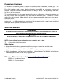
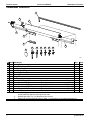
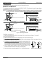
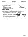
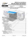
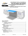
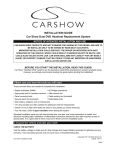
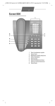
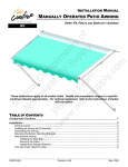
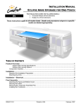
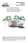
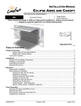
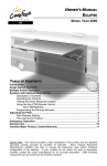
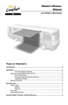
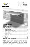
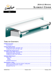
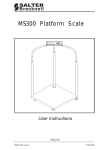
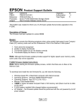
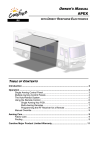
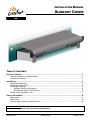
INSTALLATION MANUAL SLIDEOUT COVER RV TABLE OF CONTENTS Product Overview .......................................................................................................................... 1 General Description and Specifications .................................................................................................. 1 Component Checklist.............................................................................................................................. 2 Installation ..................................................................................................................................... 3 Mounting the Brackets ............................................................................................................................ 3 Installing an Awning Rail......................................................................................................................... 4 Mounting the Awning .............................................................................................................................. 4 Setting the Anti-Lock Assembly ...................................................................................................... 4 Mounting the Roller Tube Assembly .............................................................................................. 5 Setting Up the Anti-Billow Lock............................................................................................................... 6 Owner Information ........................................................................................................................A Maintenance .......................................................................................................................................... A Fabric Care ............................................................................................................................................ A Carefree Major Product Limited Warranty ............................................................................................. B INSTALLER'S NOTE: WHEN COMPLETED WITH THE INSTALLATION, CUT OFF THE LAST SHEET OF THIS MANUAL AND PLACE WITH THE COACH OWNER INFORMATION. 052559-001r4 Printed in USA February, 2012 PROPRIETARY STATEMENT The SLIDEOUT COVER is a product of Carefree of Colorado, located in Broomfield, Colorado, USA. The information contained in or disclosed in this document is considered proprietary to Carefree of Colorado. Every effort has been made to ensure that the information presented in the document is accurate and complete. However, Carefree of Colorado assumes no liability for errors or for any damages that result from the use of this document. The information contained in this manual pertains to the current configuration of the models listed on the title page. Earlier model configurations may differ from the information given. Carefree of Colorado reserves the right to cancel, change, alter or add any parts and assemblies, described in this manual, without prior notice. Carefree of Colorado agrees to allow the reproduction of this document for use with Carefree of Colorado products only. Any other reproduction or translation of this document in whole or part is strictly prohibited without prior written approval from Carefree of Colorado. SAFETY INFORMATION WARNING A WARNING INDICATES A POTENTIALLY HAZARDOUS SITUATION WHICH, IF NOT AVOIDED, COULD RESULT IN DEATH OR SERIOUS INJURY AND/OR MAJOR PROPERTY DAMAGE. CAUTION A CAUTION INDICATES A POTENTIALLY HAZARDOUS SITUATION THAT MAY CAUSE MINOR TO MODERATE PERSONAL INJURY AND/OR PROPERTY DAMAGE. IT MAY ALSO BE USED TO ALERT AGAINST UNSAFE PRACTICES. NOTE: A note indicates further information about a product, part, or step. Tip: A tip provides helpful suggestions. Safety Notes: Always disconnect battery or power source before working on or around the electrical system. Always wear appropriate safety equipment (i.e. goggles). Always use appropriate lifting devices and/or helpers when lifting or holding heavy objects. When using fasteners, use care to not over tighten. Soft materials such as fiberglass and aluminum can be "stripped out" and lose the ability to grip and hold. Reference Publications located @ www.carefreeofcolorado.com:' 052559-001 Installation Manual 052559-301 Service Manual Carefree of Colorado a Scott Fetzer company 2145 W. 6th Avenue Broomfield, CO 80020 303-469-3324 ♦ www.carefreeofcolorado.com CAREFREE OF COLORADO INSTALLATION MANUAL SLIDEOUT COVER PRODUCT OVERVIEW GENERAL DESCRIPTION AND SPECIFICATIONS Light weight SOK with style and performance; Simple Installation; Two mounting bracket sizes available to accommodate a range of room flange sizes; Carefree's innovative automatic anti-billow lock securely holds the fabric during travel. The lock automatically engages when the room is closed and automatically releases when the room is opened; 4 3/8” Width = Box Length + 10.1” (approx.) Fabric = Box Length + 4.5” (approx.) Striker Plate Anti Billow Lock 5 1/4” 7 3/8” 17 3/4” Shown with tall bracket, dimensions are approximate. Actual dimensions may vary based on installation and room configuration. cs007 Figure 1. General Dimensions. AVAILABLE LENGTHS: (measured box length) 42" - 196" AVAILABLE EXTENSION: Up to 42" One spring mounted in RH end of roller tube FABRIC TENSION White, Black COLOR: Hardware: Vinyl (refer to sales literature for available colors) Fabric: Base Weight @ 42" Box Length = 13.5 lbs; for every 12" increase, add 1 lb WEIGHT: Standard Weight calculation is approximate. Actual weight may vary based on specific installation details 052559-001r4 1 SLIDEOUT COVER INSTALLATION MANUAL CAREFREE OF COLORADO COMPONENT CHECKLIST 1 8 2 3 5 6 7 9 10 11 12 13 14 4 cs003 ITEM DESCRIPTION 1 Awning Rail 2 Roller Tube Assy w/ Fabric 3 End Cap Assy, LH 4 End Cap Assy, RH 5 Mounting Bracket, Tall 6 Mounting Bracket, Short 7 Striker Plate 8 Pin Tab, Lock 9 Screw, Self-Drilling, HWH 10 Screw, Pan Head Sq Drive 11 Screw, Pan Head Sq Drive 12 Screw, Oval Head, Self Drilling 13 Screw, Pan Head Sq Drive 14 Screw, HWH NOTES: 1. 2. 3. 2 Bracket Mount Striker Attach Roller Tube Attach Pin Tab Attach Extension Attach Fabric Attach #12 x 1 1/4 #10 x 1 #10-32 x 1/2 #10 x 1/2 #10 x 1/2 #6 x 3/8 QTY NOTE 1 3 1 1 1 2 2 2 2 1 1 10 2 2 2 4 2 Awning configuration is specified at time of order, including awning length, fabric color etc. Check awning assembly against original purchase order. Bracket style (item 6 or 7) is specified at time of order. Awning rail must be specified at time of order. A screw packet is included with awning rail. 052559-001r4 CAREFREE OF COLORADO INSTALLATION MANUAL SLIDEOUT COVER INSTALLATION During installation, the room should be closed until instructed otherwise. MOUNTING THE BRACKETS Two brackets are available for mounting the SLIDEOUT COVER. The tall bracket is used for large flanges, the short bracket is used for smaller flanges. NOTE: The mounting surface must have sufficient framing or backing to support the brackets and allow the use of the screws. Aluminum or fiberglass skins are not adequate to support the installation. Awning Rail Place Bracket Against Top and Side Flange Edges .88” (max clearance from mounting surface) 6”-7” 5.25” max #12 x 1 1/4 Self Drilling Screw (5 per bracket) Tall Bracket Awning Rail Place Bracket Against Top and Side Flange Edges .88” (max clearance from mounting surface) 5”-6” 3.5” max #12 x 1 1/4 Self Drilling Screw (5 per bracket) Short Bracket cs001 Figure 2. Mounting the Brackets. If installing a new awning rail: 1. Align the mounting brackets with the inner edges of the top and side room flanges. Go to step 5. If using an existing awning rail: 2. Measure the distance from the inner flange edge to the center of the awning rail. 3. If the distance is within the range shown, align the mounting brackets with the inner edges of the top and side room flanges. Go to step 5. 4. If the distance is outside the range shown, adjust the vertical position of the bracket to match the acceptable range. The bracket can be mounted below or on the flange as long as the screws enter the structure of the room and the position does not exceed the maximum height to top of flange as shown. 5. Using a quality silicone sealant, coat the mounting surface of the bracket with particular attention around the mounting holes. cs004 6. Attach the brackets using the supplied #12 x 1 1/4 self-drilling screws. 052559-001r4 Figure 3. Alternate Mounting. 3 SLIDEOUT COVER INSTALLATION MANUAL CAREFREE OF COLORADO INSTALLING AN AWNING RAIL 1. Measure up from the bracket as shown in Figure 2. This is the centerline of the awning rail slot. 2. Seal the back of the rail with silicone sealant or putty tape. 3. Align the centerline of the awning rail and attach using #10 x 3/4 screws. Position the slot pointing down. To aid sliding the canopy into position: 4. (Detail C) Using a screwdriver slightly spread open one end of the awning rail. Spread open the end of the awning rail 5. Clean and deburr the end of the rail. 6. Spray inside the rail track with silicone lubricant. MOUNTING THE AWNING cs005 Figure 4. Awning Rail. Setting the Anti-Lock Assembly The antilock plunger is mounted in the LH end cap as a standard installation. If the plunger interferes with equipment on the coach wall (i.e. lights, vents, etc) the plunger can be moved to the RH end cap. 1. Lay the two end caps down with the inside of the caps facing up. 2. In the LH end cap, remove the screw and washer that attaches the plunger. Remove the plunger and bushing assy from the end cap. 3. Install the bushings and plunger in the RH end cap and secure using the screw and washer removed previously. Note that the plunger is flipped (screw is above the scale) as shown. Bushing Assy Plunger Screw & Washer cs008 Figure 5. Switching the Plunger. 4. The adjustment of the plunger and placement of the striker plate is done after completing the installation. Refer to page 6. 4 052559-001r4 CAREFREE OF COLORADO INSTALLATION MANUAL SLIDEOUT COVER Mounting the Roller Tube Assembly Right End Cap #6 x 3/8 Screw (2 plcs) 10-32 x 1/2 Screw (1 for each endcap) DETAIL A Align Flats Left End Cap ail into R abric ver Room F e d Sli enter O and C DETAIL B #10 x 1/2 Screw (2 per bracket) DETAIL C Lock Pin cs002 Figure 6. Mounting the Roller Tube. 1. (Detail A) Slide the end cap extension onto the mounting bracket. Do not attach at this time. 2. Repeat for the other side. CAUTION DO NOT REMOVE THE SPRING LOCKING PIN UNTIL INSTRUCTED AFTER ALL STEPS ARE COMPLETE. 3. Unroll some of the fabric from the roller tube. 4. Slide the polyrod and fabric into the awning rail. Center the fabric over the room. 5. Roll up the slack material onto the roll bar. CAUTION Failure to roll up the slack before installing the roller tube will reduce the spring tension. Reduced spring tension may cause the fabric to sag and not roll up correctly when the room is closed. 6. (Details B and C) On the RH side (spring side), slide the end cap onto the roller tube spindle. Align the flats of the spindle with the flats in the end cap. The roller tube should be oriented with the spring lock pin facing out. 7. Secure the end cap to the roller tube using one (1) 10-32 x 1/2 pan head cap screw. Torque screw to 25-35 in-lbs. 8. Repeat steps 7 and 8 for the LH end cap. 9. Center the roller tube and fabric over the room. 10. From the bottom, secure the end cap extensions to the mounting bracket using two (2) each #10 x 1/2 screws. CAUTION THE ROLLER TUBE HAS A PRE-WOUND SPRING. WHEN THE SPRING LOCK PIN IS REMOVED, THE ROLLER TUBE SPRING WILL QUICKLY ROLL UP ANY SLACK MATERIAL. USE CARE THAT HANDS AND FINGERS ARE OUT OF THE WAY. 11. (Detail C) Remove the spring locking pin from the end of the roller tube assembly. This is located on the right end of the roller tube. Awning Rail Fabric 1" Polyrod #6 x 3/8 Screw 12. Open and close the room to ensure that the fabric is rolling up straight SOK3034a Figure 7. Securing the Fabric. on the rollbar. 13. Secure the fabric to the awning rail using two #6 x 3/8 screws through the rail and fabric. 052559-001r4 5 SLIDEOUT COVER INSTALLATION MANUAL CAREFREE OF COLORADO SETTING UP THE ANTI-BILLOW LOCK 1. Fully close the room if open. Plunger 2. (Detail A) Press the plunger forward into the cap until it stops. 1/4” 3. Turn the adjustment bolt until there is a 1/4" gap between the coach wall and the head of the screw. NOTE: Two adjustment bolts are included. The shorter bolt will accommodate most installations; the longer bolt is for installations with a longer distance between plunger and wall. The graphic below shows the application ranges for each. Min. = 1 3/16” Max. = 2 3/16” DETAIL A Pin Tab Striker Plate Min. = 7/16” Max. = 1 3/16” Rear Face of Plunger #10 x 1 Screw (2 plcs) Maximum Minimum Wall DETAIL B Wall cs026 4. On the coach wall, mark the spot that is in line with the center of the adjustment bolt. Plunger 5. Open the room a few inches. 6. (Detail B) At the mark made previously, mount the striker plate using two (2) #10 x 1 screws. 7. Close the room. 8. Using the flats on the adjustment bolt, adjust as required so that the bolt head contacts the striker plate when the plunger is pushed forward into the cap. #10 x 1/2 Screw (2 plcs) 5/16” (minimum) Pin Tab Assy DETAIL C cs006 Figure 8. Anti-Billow Lock. 9. (Detail C) Set the pin tab on the roller. Align the pin tab assembly as shown. If necessary, adjust the position so that the screw holes DO NOT line up on any slots of the roller tube. When adjusting the position, rotate the tab away from the plunger. 10. Attach the pin tab using two (2) #10 x 1/2 oval head screws. 11. To test the plunger: 11.1. Pull up on the fabric between the roller tube and awning rail. Note: Do not move the fabric by twisting the roller tube. 11.2. 6 The plunger should move back against the striker plate and stop the roller tube from turning. 052559-001r4 CAREFREE OF COLORADO INSTALLATION MANUAL SLIDEOUT COVER NOTES: 052559-001r4 7 OWNER INFORMATION SLIDEOUT COVER RV Automatically opens and closes with the room. Shades the top of the room to help cool the interior. The positive slope protects the room from water, dirt and debris when the room is extended. Automatic anti-billow lock when the room is closed. No manual adjustments or setting are required. MAINTENANCE Maintaining the Carefree Slideout Cover is easy. Just follow these basic steps: Periodically check that the fasteners are tight. Tighten if necessary. Keep the awning fabric clean. FABRIC CARE CAUTION DO NOT USE OIL BASED CLEANERS OR ANY CAUSTIC, GRANULATED, OR ABRASIVE TYPE CLEANERS ON YOUR CAREFREE PRODUCT. 1. One of the best ways to keep the fabric looking good and to delay the need for deep or vigorous cleanings is to hose fabrics off on a monthly basis with clear water. This practice will help prevent dirt from becoming deeply imbedded in the fabric. In most environments, a thorough cleaning is only required every two to three years. 2. When it’s time for a thorough cleaning, the fabric can be cleaned while still on the coach. For Vinyl Fabric – Use a soft brush and warm water with soap. For Acrylic Fabric – Use a stiff brush and warm water with soap. 3. When cleaning the fabric, it is important to observe the following: Always use a natural soap, never detergent. Water should be cold to lukewarm, never more than 100F. Air-dry only. Never apply heat to the fabric. Always allow the fabric to dry thoroughly before rolling up the awning. Mildew Mildew is a fungus growth that looks like dirt. Vinyl coated polyester fabrics are mildew resistant because of a chemical biocide in the vinyl coating. Under ordinary conditions, mildew will not appear. However, in areas where high temperature and humidity are common, mildew can be a problem and required the material to be cleaned more frequently. Thoroughly rinse the fabric with clean water and allow to air dry completely before rolling up the fabric. Pooling When water collects on the top of the fabric, this is known as "pooling". This can occur during inclement weather or if a running air conditioner discharges over the awning. The water is dumped when the awning is retracted. It is recommended that if water accumulates on the top; retract the room in steps (8"-12") to dump the water. This will help prevent the fabric from stretching or distorting. IMPORTANT NOTE: If the room must be closed during wet weather (rain), close the room in increments (approximately 8"-12"). This is to allow water to run off while the room is closing and prevent sudden pooling. 052559-001r2 A CAREFREE OF COLORADO OWNER INFORMATION SLIDEOUT COVER CAREFREE MAJOR PRODUCT LIMITED WARRANTY Carefree of Colorado (hereafter referred to as Carefree) warrants to the first retail Purchaser that the Carefree Product is free of defects in material and workmanship within the terms and conditions as set forth in the warranty statement available online at www.carefreeofcolorado.com. Carefree’s obligation under this warranty is limited to the repair or replacement, at Carefree’s option, of any defective component with new or factory refurbished components. OWNER MUST RETAIN THE ORIGINAL PROOF OF PURCHASE AND/OR HAVE THE PRODUCT WARRANTY REGISTRATION ON FILE AT CAREFREE FOR WARRANTY CLAIMS. THIS WARRANTY IS NOT TRANSFERABLE. For - Warranty Duration; - Warranty Coverage and Exclusions; - Warranty Terms of Coverage; and, - Warranty Claim Procedures Refer to publication 052580-111 "Carefree Major Product Limited Warranty" available online at www.carefreeofcolorado.com Register your Carefree products on-line at www.carefreeofcolorado.com IMPORTANT NOTICE: It is strongly recommended that adjustments and repairs be performed by trained technicians at your Authorized Carefree Dealer. Work performed by non-authorized persons or businesses may void warranty. Carefree of Colorado B 2145 W. 6th Avenue Broomfield, CO 80020 a Scott Fetzer company 052559-001r4