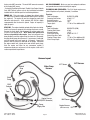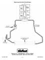
1
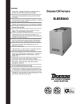
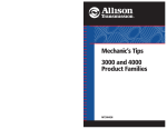
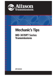
EDELBROCK CRATE ENGINE
SUPERCHARGED FORD 5.0L COYOTE
Part #46770, 46880
®
GENERAL INSTALLATION INSTRUCTIONS
PLEASE study these instructions carefully before beginning this installation. If you have any questions, please call our Technical Hotline at:
1-800-416-8628, 7:00 AM - 5:00 PM Pacific Standard Time, Monday through Friday.
Proper installation is the responsibility of the installer. Improper installation will void the manufacturer’s
warranty and may result in poor performance and engine or vehicle damage.
IMPORTANT NOTE: This instruction sheet provides general installation guidelines which can affect your warranty. Read it carefully. It is not our
intent to cover each detail of installation here as the procedures are vehicle specific. We want to caution you that installing an engine is a complicated
procedure that requires a good general knowledge of automotive mechanics. It is a good idea to refer to the factory service manual for your vehicle.
If you are not confident that you can complete the engine installation successfully, we suggest you consider having it installed by an experienced
mechanic.
CAUTION: This engine is NOT INTENDED for marine use. Not legal for use in pollution controlled vehicles.
DESCRIPTION: This crate engine is built using a Ford aluminum 5.0L block with a forged and balanced crankshaft, forged Manley
H-Beam connecting rods and Mahle forged aluminum pistons which are then combined with Edelbrock’s E-Force Supercharger to
produce 700 horsepower and 606 ft-lbs. of torque on 91 octane pump gas. Its compact design allows for a seamless swap into most
platforms, eliminating the need for modifications to your engine bay or hood.
Available Variants:
P/N 46770 - Supercharged Ford 5.0L Crate Engine, Complete
With Electronics
P/N 46880 - Supercharged Ford 5.0L Crate Engine, Complete
Without Electronics
PRODUCT SPECIFICATIONS:
Displacement:
4.957L (302 ci)
Bore / Stroke
3.629” bore / 3.649”stroke
Horsepower:
700
Torque: 606
Compression:
9.5:1
Block:
New Ford Aluminum
Cylinder Heads:Factory Aluminum 54.5 - 57.5cc
Supercharger:
Edelbrock E-Force
Pistons:
Mahle Forged Aluminum
Crankshaft:
Forged 4340
Camshaft Duration:
Intake: 260°; Exhaust: /263°
Camshaft Lift:
Intake: 12mm; Exhaust 11mm
Rocker Arms:
2:1 ratio
Spark Plugs:
Ford M-12405-M50 (.032 Gap)
Fuel Type:
Requires 91 Octane At All Times
Firing Order:
1-5-4-8-6-3-7-2
Maximum Rated RPM: 7200 RPM
Warranty:
2 Year/Unlimited Mileage
Ancillary Parts Required For Installation
• Low Temperature Radiator (LTR)
- #15405: Full Face Universal Fit
- #15406: Compact Universal Fit
- #15407: Compact, 16” x 16”, Universal Fit
• LTR/Intercooler Plumbing
• Fuel Pump - A minimum fuel flow of 75gph @ 60psi differential
pressure is required. It is the responsibility of the customer
to ensure that adequate fuel flow is achieved at the operating
voltage of the fuel pump. Engine damage can occur if fuel flow is
insufficient.
Part # 46770, 46880
Rev. 3/20/13 - QT/mc
• Fuel Pressure Regulator with Boost Reference.
General Supercharger Plumbing Installation
- Determine the ideal mounting location for the intercooler heat
exchanger (not included). It is important that the heat exchanger
receives the coldest air possible, which means mounting it in front
of the radiator, A/C condenser and any oil or trans cooler the vehicle
might have equipped.
- Determine the ideal mounting location for the water pump.
A universal mounting bracket has been supplied to simplify
installation. Please note that the pump should be mounted no
higher than the inlet of the heat exchanger. The inlet of the
pump is in line with the axis of the pump motor, while the outlet
extends out perpendicularly from the pump body.
- Determine the ideal mounting location for the intercooler reservoir
tank. To simplify installation, a universal mounting bracket and a
groove around the perimeter of the tank, for use with a large worm
clamp, have been included.
NOTE: Be sure to mount the tank as high as possible to prevent air
bubbles from accumulating in the cooling system.
- Refer to the diagram on Page 3 for the suggested intercooler
plumbing (not included). Note that the intercooler routing can be
inverted so that the pump and tank are mounted on the driver side.
Regardless of component mounting locations, it is important that
the correct direction of flow is maintained.
General harness Installation
- Determine the ideal mounting location for the relay and fuse
holder on the water pump harness. Connect the POSITIVE (+) lead
to a CONSTANT +12V power source. Connect the GROUND (-) lead
to a chassis ground. Connect the water pump connector to the
electric water pump. Connect the factory female EVAP connector
to the male EVAP connector on the water pump harness. Then plug
the female end of the water pump harness onto the EVAP solenoid.
- Install the ACT Harness to the ACT sensor on the rear of the
supercharger manifold. The female MAF adaptor connects to the
Page 1
©2013 Edelbrock, LLC
Brochure #63-46770
factory male MAF connector. The male MAF connector connects
to the factory MAF sensor.
- If using the Ford Racing Electronic Throttle Crate Engine Controls
Pack (#46770 Only), please refer to the installation instructions
included with the controls pack for installation guidelines.
ENGINE OIL: This crate engine is shipped dry without engine
oil. Make sure to add the recommended Ford oil prior to priming
the engine oil. The engine oil must be changed no more than
300 miles after break-in. A full synthetic SAE 5W-50 is highly
recommended after the break-in period. Engine oil capacity is
eight (8) quarts.
OIL PAN CLEARANCE: Make sure you have adequate subframe
and ground clearance before installing the engine.
Flexplate:
Ford Part Number:
Converter Bolt Pattern:
Outside Diameter:
Starter Ring Gear Tooth:
Torque Spec:
BL3Z6375A (OEM)
8 Bolt, 11.5”
14.25”
164
177 lb-in, Plus additional 60°
START-UP: The engine should be primed with oil prior to starting.
Install an oil pressure gauge to the existing oil pressure sensor.
Remove the spark plugs and disconnect the engine control unit
as well as the injector wires. NOTE: Make sure ignition and
fuel are not provided to the engine. Once fuel and spark have
been disabled, crank the engine using the starter for 10 seconds,
checking the oil gauge for oil pressure. If no pressure is indicated,
wait 30 seconds and crank again for 10 seconds. Repeat this
process until oil pressure is indicated on the gauge. Reconnect
the engine control unit, injector wires and reinstall spark plugs.
Start the engine and listen for any uncommon sounds. If
uncommon sounds are not present, run the engine at idle until it
reaches operational temperatures.
Flywheel:
Ford Part Number:
Flywheel Bolt Pattern:
Outside Diameter:
Clutch Bolt Pattern:
Starter Ring Gear Tooth:
Flywheel Torque Spec:
Clutch Torque Spec:
BR3Z6375D (OEM)
8 Bolt
14.25”
6 Bolt, 10.5/11.5”
164
177 lb-in, Plus additional 60°
35 ft-lbs, Plus additional 60°
FLYWHEELS AND FLEXPLATES: The 5.0L Coyote engines use
special flexplates or flywheels (included). See below:
Harness Layout
Water Pump
Harness
Ground
Strap
Water
Pump
ACT Sensor
ACT Harness
Relay
EVAP
Solenoid
Fuse
Engine Harness
(EVAP Connector)
Power
Supply Wire
Part # 46770, 46880
Rev. 3/20/13 - QT/mc
Page 2
MAF Sensor
Engine Harness
(MAF Connector)
©2013 Edelbrock, LLC
Brochure #63-46770
Supercharger Intercooler Routing Diagram
LTR Plumbing
Not Included
Intercooler
Reservoir Tank
Low Temp Radiator (LTR)
-Not IncludedElectric
Water Pump
®
Edelbrock LLC • 2700 California St. • Torrance, CA 90503
Tech Line: 1-800-416-8628 • Office Line: 310-781-2222
Part # 46770, 46880
Rev. 3/20/13 - QT/mc
Page 3
©2013 Edelbrock, LLC
Brochure #63-46770