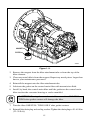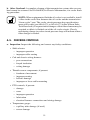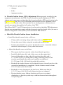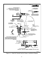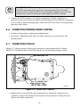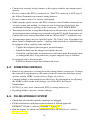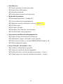
1
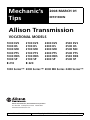
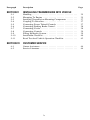
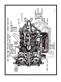
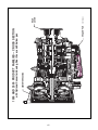
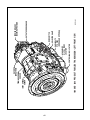
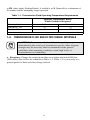
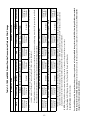
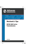
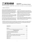
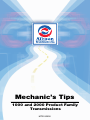
Mechanic’s Tips
1000 and 2000 Product Family
Transmissions
MT3190EN
Mechanic’s
Tips
2004 MARCH 01
MT3190EN
Allison Transmission
VOCATIONAL MODELS
1000 EVS
1000 HS
1000 MH
1000 PTS
1000 RDS
1000 SP
B 210
2100 EVS
2100 HS
2100 MH
2100 PTS
2100 RDS
2100 SP
B 220
2200 EVS
2200 HS
2200 MH
2200 PTS
2200 RDS
2200 SP
2500 EVS
2500 HS
2500 MH
2500 PTS
2500 RDS
2500 SP
1000 Series™ 2000 Series™ 2000 MH Series 2400 Series™
Allison Transmission, General Motors Corporation
P.O. Box 894 Indianapolis, Indiana 46202-0894
www.allisontransmission.com
Printed in USA
Copyright © 2004 General Motors Corporation
i
WARNINGS, CAUTIONS, AND NOTES
IT IS YOUR RESPONSIBILITY to be completely familiar with the warnings and
cautions described in this handbook. It is, however, important to understand that
these warnings and cautions are not exhaustive. Allison Transmission could not
possibly know, evaluate, and advise the service trade of all conceivable ways in
which service might be done or of the possible hazardous consequences of each
way. The vehicle manufacturer is responsible for providing information related to
the operation of vehicle systems (including appropriate warnings, cautions, and
notes). Consequently, Allison Transmission has not undertaken any such broad
evaluation. Accordingly, ANYONE WHO USES A SERVICE PROCEDURE OR
TOOL WHICH IS NOT RECOMMENDED BY ALLISON TRANSMISSION OR
THE VEHICLE MANUFACTURER MUST first be thoroughly satisfied that neither
personal safety nor equipment safety will be jeopardized by the service methods
selected.
Proper service and repair is important to the safe, reliable operation of the
equipment. The service procedures recommended by Allison Transmission (or the
vehicle manufacturer) and described in this handbook are effective methods for
performing service operations. Some of these service operations require the use of
tools specially designed for the purpose. The special tools should be used when and
as recommended.
Three types of headings are used in this manual to attract your attention. These
warnings and cautions advise of specific methods or actions that can result in personal
injury, damage to the equipment, or cause the equipment to become unsafe.
WARNING: A warning is used when an operating procedure, practice,
etc., if not correctly followed, could result in personal injury or loss of life.
CAUTION: A caution is used when an operating procedure,
practice, etc., if not strictly observed, could result in damage to or
destruction of equipment.
NOTE: A note is used when an operating procedure, practice, etc., is
essential to highlight.
TRADEMARK INFORMATION
DEXRON® is a registered trademark of General Motors Corporation.
Allison DOC™ is a trademark of General Motors Corporation.
TranSynd™ is a trademark of Castrol Ltd.
ii
TABLE OF CONTENTS
Paragraph
SECTION I
1–1
1–2
1–3
1–4
1–5
1–6
1–7
1–8
1–9
SECTION II
2–1
2–2
2–3
2–4
2–5
2–6
SECTION III
3–1
3–2
3–3
3–4
3–5
SECTION IV
4–1
4–2
4–3
4–4
4–5
Description
Page
PREVENTIVE MAINTENANCE
Periodic Inspections And Care. . . . . . . . . . . . . . . . . . . . . . .
Importance Of Proper Transmission Fluid Level. . . . . . . . .
Transmission Fluid Check . . . . . . . . . . . . . . . . . . . . . . . . . .
Keeping Fluid Clean . . . . . . . . . . . . . . . . . . . . . . . . . . . . . .
Fluid Recommendations. . . . . . . . . . . . . . . . . . . . . . . . . . . .
Transmission Fluid And Filter Change Intervals . . . . . . . . .
Transmission Fluid Contamination . . . . . . . . . . . . . . . . . . .
Transmission Fluid And Filter Change Procedure. . . . . . . .
Oil Vent (Breather) . . . . . . . . . . . . . . . . . . . . . . . . . . . . . . .
1
3
3
10
10
11
13
14
16
REMOVING TRANSMISSION
Draining Transmission . . . . . . . . . . . . . . . . . . . . . . . . . . . . .
Disconnecting Controls . . . . . . . . . . . . . . . . . . . . . . . . . . . .
Uncoupling From Driveline, Engine, And Vehicle . . . . . . .
Removing The Transmission . . . . . . . . . . . . . . . . . . . . . . . .
Removing The Flexplate Adapter . . . . . . . . . . . . . . . . . . . .
Removing Output Flange Or Yoke . . . . . . . . . . . . . . . . . . .
17
17
18
18
19
19
PREPARING THE TRANSMISSION FOR INSTALLATION
Checking Input Components . . . . . . . . . . . . . . . . . . . . . . . .
Installing Output Flange Or Yoke . . . . . . . . . . . . . . . . . . . .
Installing PTO . . . . . . . . . . . . . . . . . . . . . . . . . . . . . . . . . . .
Installing Fill Tube And Seal . . . . . . . . . . . . . . . . . . . . . . . .
Checking Plugs And Openings . . . . . . . . . . . . . . . . . . . . . .
20
20
21
24
25
PREPARING VEHICLE FOR TRANSMISSION
INSTALLATION
Engine, Transmission Adaptation Requirements . . . . . . . . .
Checking Flexplate Drive Assembly . . . . . . . . . . . . . . . . . .
Chassis And Driveline Inspection . . . . . . . . . . . . . . . . . . . .
Cooler, Filter, And Lines . . . . . . . . . . . . . . . . . . . . . . . . . . .
Checking Controls . . . . . . . . . . . . . . . . . . . . . . . . . . . . . . . .
iii
26
30
30
31
32
Paragraph
Description
SECTION V
INSTALLING TRANSMISSION INTO VEHICLE
5–1
5–2
5–3
5–4
5–5
5–6
5–7
5–8
5–9
5–10
5–11
SECTION VI
6–1
6–2
Page
Handling. . . . . . . . . . . . . . . . . . . . . . . . . . . . . . . . . . . . . . . .
Mounting To Engine . . . . . . . . . . . . . . . . . . . . . . . . . . . . . .
Installing Transmission Mounting Components . . . . . . . . .
Coupling To Driveline . . . . . . . . . . . . . . . . . . . . . . . . . . . . .
Connecting Power Takeoff Controls . . . . . . . . . . . . . . . . . .
Connecting Parking Brake Control . . . . . . . . . . . . . . . . . . .
Connecting Cooler . . . . . . . . . . . . . . . . . . . . . . . . . . . . . . . .
Connecting Controls . . . . . . . . . . . . . . . . . . . . . . . . . . . . . .
Filling Hydraulic System . . . . . . . . . . . . . . . . . . . . . . . . . . .
Installation Checklist . . . . . . . . . . . . . . . . . . . . . . . . . . . . . .
Road Test And Vehicle Operation Checklist . . . . . . . . . . . .
35
35
37
37
37
38
38
39
39
40
42
CUSTOMER SERVICE
Owner Assistance. . . . . . . . . . . . . . . . . . . . . . . . . . . . . . . . .
Service Literature . . . . . . . . . . . . . . . . . . . . . . . . . . . . . . . . .
iv
44
44
PREFACE
This handbook is a mechanic’s reference for maintaining, removing, or installing
1000 and 2000 Product Families transmissions. All features of the transmission and
the vehicle involved in installation procedures are discussed. The information
presented will help the mechanic maintain, remove, or install the transmission in a
manner that assures satisfactory operation and long service life. For additional
detailed information, refer to the appropriate transmission service manual and
electronic controls troubleshooting manual.
Unless specifically indicated otherwise, this handbook refers to all 1000 and 2000
Product Families transmissions. The differences between the various transmissions
are explained as required.
v
vi
CONTROL MAIN FILTER
TORQUE
CONVERTER
ASSEMBLY
OUTPUT YOKE
MAIN SHAFT
MAIN HOUSING MODULE
• MAIN HOUSING
• C3 CLUTCH
• C4 CLUTCH
• C5 CLUTCH
REAR COVER MODULE
• REAR COVER
• OUTPUT SPEED SENSOR
• OUTPUT SHAFT
• P3 PLANETARY
• PARK PAWL (1000/2200 ONLY)
P2 PLANETARY
P1 PLANETARY
DEEP OIL PAN
CONTROL VALVE MODULE
SUCTION FILTER
ROTATING CLUTCH MODULE
• TONE WHEEL (IF NO PTO) OR PTO DRIVE GEAR
• C2 CLUTCH
• C1 CLUTCH
• TURBINE SHAFT
V04525.02.02
CONVERTER HOUSING/FRONT SUPPORT MODULE
• CONVERTER HOUSING
• INPUT SPEED SENSOR
• OIL PUMP
• FRONT SUPPORT TURBINE
SPEED
SENSOR
1000 AND 2000 PRODUCT FAMILIES — CROSS SECTION
vii
CONVERTER HOUSING
SHALLOW PAN
with Optional Converter Housing, Rear Cover, and Shallow pan
1000 AND 2000 PRODUCT FAMILIES — CROSS SECTION
V05719.02.02
REAR
COVER
viii
CONTROL MAIN OIL FILTER
AVAILABLE
OIL FILL TUBE
LOCATION
SAE 6-BOLT
PTO PAD
(DRIVE GEAR OPTIONAL)
SELECTOR SHAFT
NSBU SWITCH
V04779.03.02
OUTPUT SPEED SENSOR
PARKING BRAKE
MOUNTING PROVISION
1000 AND 2000 PRODUCT FAMILIES TRANSMISSION – LEFT-FRONT VIEW
OIL VENT
(BREATHER)
TURBINE SPEED
SENSOR
INPUT SPEED
SENSOR
ix
MAIN ELECTRICAL
CONNECTOR
AVAILABLE
OIL FILL TUBE
LOCATION
SAE 6-BOLT
PTO PAD
(DRIVE GEAR OPTIONAL)
V04780.01.05
MOUNTING PAD
(SAE #3 HOUSING ONLY)
COOLER PORTS
1000 AND 2000 PRODUCT FAMILIES TRANSMISSION – RIGHT-REAR VIEW
PROVISION FOR
CUSTOMER-SUPPLIED
SPEED SENSOR OR
TACHOGRAPH
(OPRIONAL)
OUTPUT SPEED
SENSOR
OIL VENT
(BREATHER)
TURBINE SPEED
SENSOR
INPUT SPEED
SENSOR
NOTES
x
PREVENTIVE
MAINTENANCE
S ECTION
I
1–1. PERIODIC INSPECTIONS AND CARE
Transmission Product Families
Beginning January 2004, Allison Transmission began shipping new 1000 and 2000
Product Families vocation specific transmission models for North America. 1000
and 2000 Product Families vocational models are:
• Emergency Vehicle Series—1000 EVS, 2100 EVS, 2200 EVS, 2500 EVS
• Highway Series—1000 HS, 2100 HS, 2200 HS, 2500 HS
• Motorhome Series—1000 MH, 2100 MH, 2200 MH, 2500 MH
• Pupil Transportation/Shuttle Series—1000 PTS, 2100 PTS, 2200 PTS,
2500 PTS
• Rugged Duty Series—1000 RDS, 2100 RDS,·2200 RDS,·2500 RDS
• Specialty Series—1000 SP, 2100 SP, 2200 SP, 2500 SP
• Bus Series—B 210, B 220
The 1000 and 2000 Product Families include the 1000/2000/2400 Series
transmissions. Refer to WATCH 309 for detailed descriptions of the vocational
models and their correlation to the existing 1000/2000/2400 Series.
Transmission Inspection
CAUTION: When cleaning the transmission, do not spray steam,
water, or cleaning solution directly at the breather (oil vent). Spraying
steam, water, or cleaning solution at the breather can force the water or
cleaning solution into the transmission and contaminate the
transmission fluid.
1
Clean and inspect the exterior of the transmission at regular intervals. Severity of
service and operating conditions determine the frequency of these inspections.
Inspect the transmission for:
• loose bolts—transmission and mounting components
• fluid leaks—repair immediately
• loose, dirty, or improperly adjusted throttle sensor or shift selector linkage
• damaged or loose hoses
• worn, frayed, or improperly routed electrical harnesses
• worn or frayed electrical connections
• worn or out-of-phase driveline U-joints and slip fittings
• clogged or dirty oil vent (breather)
Vehicle Inspection
Check the vehicle cooling system occasionally for evidence of transmission fluid
which would indicate a faulty oil cooler.
Welding
CAUTION: When welding on the vehicle:
• DO NOT WELD on the vehicle without disconnecting
from the TCM all control system wiring harness connectors.
• DO NOT WELD on the vehicle without disconnecting
TCM battery power and ground leads.
• DO NOT WELD on any control components.
• DO NOT CONNECT welding cables to any control components.
A label describing on-vehicle welding precautions is available from your authorized
Allison service dealer and should be installed in a conspicuous place. A vehicle used
in a vocation that requires frequent modifications or repairs involving welding must
have an on-vehicle welding label (SA2607).
2
1–2. IMPORTANCE OF PROPER TRANSMISSION FLUID LEVEL
Transmission fluid cools, lubricates, and transmits hydraulic power.
Always maintain proper fluid level. If fluid level is too low, the torque
converter and clutches do not receive an adequate supply of fluid and the
transmission overheats. If the level is too high, the fluid aerates—causing
the transmission to shift erratically and overheat. Fluid may be expelled
through the breather or dipstick tube when the fluid level is too high.
1–3.
TRANSMISSION FLUID CHECK
WARNING: For vehicles containing 1000 or 2200 models, each time
you park the vehicle or leave the operator’s station with the engine
running, do the following.
• Bring the vehicle to a complete stop using the service brake.
• Make sure that the engine is at low idle rpm.
• Put the transmission in P (Park).
• Engage the P (Park) range by slowly releasing the service brake.
• Apply the emergency brake and/or parking brake, if present, and
make sure it is properly engaged.
• If the operator’s station will be unoccupied with the engine
running, chock the wheels and take any other steps necessary to
keep the vehicle from moving.
If this procedure is not followed, the vehicle can move suddenly and
you or others could be injured.
WARNING: For vehicles containing 2100 or 2500 models with autoapply parking brakes, each time you park the vehicle or leave the
operator’s station with the engine running, do the following.
• Bring the vehicle to a complete stop using the service brake.
• Make sure that the engine is at low idle rpm.
• Put the transmission in PB (Auto-Apply Parking Brake). Make
sure that the parking brake is properly engaged.
• Apply the emergency brake, if present, and make sure it is properly
engaged.
• If the operator’s station will be unoccupied with the engine
running, chock the wheels and take any other steps necessary to
keep the vehicle from moving.
If this procedure is not followed, the vehicle can move suddenly and
you or others could be injured.
3
WARNING: For vehicles containing 2100 or 2500 models without
auto-apply parking brakes, each time you park the vehicle or leave the
operator’s station with the engine running, do the following.
• Bring the vehicle to a complete stop using the service brake.
• Make sure that the engine is at low idle rpm.
• Put the transmission in N (Neutral).
• Apply the emergency brake and/or parking brake and make sure
they are properly engaged.
• If the operator’s station will be unoccupied with the engine
running, chock the wheels and take any other steps necessary to
keep the vehicle from moving.
If this procedure is not followed, the vehicle can move suddenly and
you or others could be injured.
NOTE: For accurate fluid level checks, be sure that the fill tube and
dipstick meet Allison Transmission specifications. Requirements for
the standard oil pan are shown in Figure 1–1 and requirements for the
shallow oil pan are shown in Figure 1–2.
When checking a long dipstick calibration:
• Be sure the dipstick contacts the oil pan surface as shown in
Figures 1–1 and 1–2.
• Take measurements from the end of the dipstick.
When checking a short dipstick calibration:
• Remove the oil pan.
• Take measurements from the oil pan splitline.
4
Figure 1–1. Fill Tube And Dipstick Requirements (Standard Oil Pan)
5
Dipstick must
contact oil pan
TYPICAL
COLD CHECK
BAND
HOT RUN
TYPICAL
COLD CHECK
BAND
HOT RUN
Fill tube to be
straight in all
vertical planes
for this distance
5.0 mm
(0.20 in)
V05803
SHORT FILL TUBE AND DIPSTICK
72.6 mm
(2.86 in)
98.9 mm
(3.89 in)
TRANSMISSION
CENTERLINE
10.0 mm
(0.39 in)
30.0 mm
(1.18 in)
OIL PAN
SPLIT LINE
Fill tube to be
straight in all
vertical planes
for this distance
5.0 mm
(0.20 in)
LONG FILL TUBE AND DIPSTICK*
72.6 mm
(2.86 in)
*Check measurements from end of dipstick
101.9 mm
(4.01 in)
10.0 mm
(0.39 in)
30.0 mm
(1.18 in)
OIL PAN
SPLIT LINE
(Ref. only)
98.9 mm
(3.89 in)
TRANSMISSION
CENTERLINE
Figure 1–2. Fill Tube And Dipstick Requirements (Shallow Oil Pan)
6
72.6 mm
(2.86 in)
Dipstick must
contact oil pan
TYPICAL
COLD CHECK
BAND
HOT RUN
TYPICAL
COLD CHECK
BAND
HOT RUN
Fill tube to be
straight in all
vertical planes
for this distance
5.0 mm
(0.20 in)
V05804
SHORT FILL TUBE AND DIPSTICK
72.6 mm
(2.86 in)
98.9 mm
(3.89 in)
TRANSMISSION
CENTERLINE
10.0 mm
(0.39 in)
30.0 mm
(1.18 in)
OIL PAN
SPLIT LINE
Fill tube to be
straight in all
vertical planes
for this distance
5.0 mm
(0.20 in)
LONG FILL TUBE AND DIPSTICK*
*Check measurements from end of dipstick
88.5 mm
(3.48 in)
10.0 mm
(0.39 in)
30.0 mm
(1.18 in)
OIL PAN
SPLIT LINE
(Ref. only)
98.9 mm
(3.89 in)
TRANSMISSION
CENTERLINE
a. Manual Fluid Check Procedure. Clean all dirt from around the end
of the fluid fill tube before removing the dipstick. Do not allow dirt or
foreign matter to enter the transmission. Dirt or foreign matter in the
hydraulic system may cause undue wear of transmission parts, make
valves stick, and clog passages. Check the fluid level using the
following procedure and report any abnormal fluid levels to your
maintenance persons.
b. Cold Check Procedure. The purpose of the cold check is to determine if the
transmission has enough fluid to be operated safely until a hot check can be made.
CAUTION: The fluid level rises as fluid temperature increases.
DO NOT fill above the “COLD CHECK” band if the transmission
fluid is below normal operating temperatures.
• Park vehicles containing 1000 or 2200 models as follows:
— Bring the vehicle to a complete stop on a level surface using the service
brake.
— Make sure that the engine is at low idle rpm.
— Put the transmission in P (Park).
— Engage the P (Park) range by slowly releasing the service brake.
— Apply the emergency brake and/or parking brake, if present, and make
sure it is properly engaged.
• Park vehicles containing 2100 or 2500 models with auto-apply parking brakes
as follows:
— Bring the vehicle to a complete stop on a level surface using the service
brake.
— Make sure that the engine is at low idle rpm.
— Put the transmission in PB (Auto-Apply Parking Brake). Make sure that
the parking brake is properly engaged.
— Apply the emergency brake, if present, and make sure it is properly
engaged.
7
• Park vehicles containing 2100 or 2500 models without auto-apply parking
brakes as follows:
— Bring the vehicle to a complete stop on a level surface using the service
brake.
— Make sure that the engine is at low idle rpm.
— Put the transmission in N (Neutral).
— Apply the emergency brake and/or parking brake and make sure they are
properly engaged.
• Chock the wheels and take any other steps necessary to keep the vehicle from
moving.
• Run the engine for at least one minute. Apply the service brakes and shift to
D (Drive), then to N (Neutral), and then shift to R (Reverse) to fill the hydraulic
system. Finally, shift to P (Park) or PB (Auto-Apply Parking Brake), if
available, or N (Neutral) and allow the engine to idle (500–800 rpm). Slowly
release the service brakes.
• With the engine running, remove the dipstick from the tube and wipe the
dipstick clean.
• Insert the dipstick into the tube and remove. Check the fluid level reading.
Repeat the check procedure to verify the reading.
• If the fluid level is within the “COLD CHECK” band, the transmission may
be operated until the fluid is hot enough to perform a “HOT RUN” check. If
the fluid level is not within the “COLD CHECK” band, add or drain as
necessary to bring it to the middle of the “COLD CHECK” band.
• Perform a hot check at the first opportunity after the normal operating sump
temperature of 71˚C–93˚C (160˚F–200˚F) is reached.
c. Hot Check Procedure.
CAUTION: The fluid must be hot to provide an accurate check. The
fluid level rises as temperature increases.
• Operate the transmission in D (Drive) range until normal operating
temperature is reached:
— sump temperature 71˚C–93˚C (160˚F–200˚F)
— converter-out temperature 82˚C–104˚C (180˚F–220˚F)
— If a transmission temperature gauge is not present, check fluid level when
the engine water temperature gauge has stabilized and the transmission
has been operated under load for at least one hour.
8
• Park vehicles containing 1000 or 2200 models as follows:
— Bring the vehicle to a complete stop on a level surface using the service
brake.
— Make sure that the engine is at low idle rpm.
— Put the transmission in P (Park).
— Engage the P (Park) range by slowly releasing the service brake.
— Apply the emergency brake and/or parking brake, if present, and make
sure it is properly engaged.
• Park vehicles containing 2100 or 2500 models with auto-apply parking brakes
as follows:
— Bring the vehicle to a complete stop on a level surface using the service
brake.
— Make sure that the engine is at low idle rpm.
— Put the transmission in PB (Auto-Apply Parking Brake). Make sure that
the parking brake is properly engaged.
— Apply the emergency brake, if present, and make sure it is properly
engaged.
• Park vehicles containing 2100 or 2500 models without auto-apply parking
brakes as follows:
— Bring the vehicle to a complete stop on a level surface using the service
brake.
— Make sure that the engine is at low idle rpm.
— Put the transmission in N (Neutral).
— Apply the emergency brake and/or parking brake and make sure they are
properly engaged.
• Chock the wheels and take any other steps necessary to keep the vehicle from
moving.
• With the engine running, remove the dipstick from the tube and wipe the
dipstick clean.
• Insert the dipstick into the tube and remove. Check fluid level reading. Repeat
the check procedure to verify the reading.
9
NOTE: Safe operating level is within the “HOT RUN” band on the
dipstick. See Figures 1–1 and 1–2. The width of the “HOT RUN” band
represents approximately 1.0 liter (1.06 quart) of fluid at normal
operating sump temperature.
• If the fluid level is not within the “HOT RUN” band, add or drain as necessary
to bring the fluid level to within the “HOT RUN” band.
d. Consistency of Readings. Always check the fluid level at least twice using the
procedure described above. Consistency (repeatable readings) is important to
maintaining proper fluid level. If inconsistent readings persist, check the
transmission breather to be sure it is clean and unclogged. If readings are still
inconsistent, contact your nearest Allison distribution or dealer.
1–4. KEEPING FLUID CLEAN
Prevent foreign material from entering the transmission by using clean containers,
fillers, etc. Lay the dipstick in a clean place while filling the transmission.
CAUTION: Containers or fillers that have been used for antifreeze
solution or engine coolant must NEVER be used for transmission
fluid. Antifreeze and coolant solutions contain ethylene glycol which,
if put into the transmission, can cause the clutch plates to fail.
1–5. FLUID RECOMMENDATIONS
Hydraulic fluids (oils) used in the transmission are important influences on
transmission performance, reliability, and durability. Only fluids meeting TES-295
(TranSynd™) or DEXRON®-III specifications are acceptable for use in the 1000
and 2000 Product Families transmissions.
To make sure the fluid is qualified for use in Allison transmissions, check for a
TES-295 or a DEXRON®-III fluid license or approval numbers on the container, or
consult the lubricant manufacturer. Consult your Allison Transmission dealer or
distributor before using other fluid types.
CAUTION: Disregarding minimum fluid temperature limits can
result in transmission malfunction or reduced transmission life.
When choosing the optimum viscosity grade of fluid to use, duty cycle, preheat
capabilities, and/or geographical location must be taken into consideration.
Table 1–1 lists the minimum fluid temperatures at which the transmission may be
safely operated without preheating the fluid. Preheat with auxiliary heating
equipment or by running the equipment or vehicle with the transmission in P (Park)
10
or PB (Auto-Apply Parking Brake), if available, or N (Neutral) for a minimum of
20 minutes before attempting range operation.
Table 1–1. Transmission Fluid Operating Temperature Requirements
Ambient Temperature Below
Which Preheat is Required
Viscosity Grade
Celsius
Fahrenheit
DEXRON®-III
TranSynd™
–27
–33
–17
–22
(Ref. SIL 13-TR-90)
1–6. TRANSMISSION FLUID AND FILTER CHANGE INTERVALS
CAUTION: Transmission fluid and filter change frequency is
determined by the severity of transmission service. More frequent
changes may be necessary than recommended in the general
guidelines when operating conditions create high levels of
contamination or overheating.
a. Frequency. Change the control main filter at or before the initial 8000 km
(5000 miles) then follow the schedule in Table 1–2. Table 1–2 is given only as a
general guide for fluid and filter change interval.
11
12
Fluid
Schedule 1. Recommended Fluid and Filter Change Intervals (Non-TranSynd™/Non-TES 295 Fluid)
25,000 Miles
25,000 Miles
50,000 Miles
50,000 Miles
(40 000 km)
(40 000 km)
(80 000 km)
(80 000 km)
12 Months
Overhaul
12 Months
24 Months
24 Months
Overhaul
Lube/Auxiliary
GENERAL VOCATION
Filters
Control Main
Internal
50,000 Miles
(80 000 km)
24 Months
Lube/Auxiliary
25,000 Miles
(40 000 km)
12 Months
Overhaul
25,000 Miles
(40 000 km)
12 Months
50,000 Miles
(80 000 km)
24 Months
50,000 Miles
(80 000 km)
24 Months
Overhaul
50,000 Miles
(80 000 km)
24 Months
50,000 Miles
(80 000 km)
24 Months
Local conditions, severity of operation or duty cycle may require more or less frequent fluid change intervals that differ from the published recommended
fluid change intervals of Allison Transmission. Transmission protection and fluid change intervals can be optimized by the use of fluid analysis. Filters must be
changed at or before recommended intervals.
* Mixture is defined as the quantity of oil remaining in the transmission after a standard fluid change combined with the quantity of TranSynd™ that is
required to fill the transmission to the proper level. A mixture of TranSynd™ or TES 295 equivalent vs. non-TranSynd™ other than as defined in this
paragraph does not meet the requirements that permit the eligibility for the recommendations given in Schedule 3.
NOTE: Change fluid/filters after recommended mileage, months, or hours have elapsed, whichever occurs first.
Severe Vocation: On/Off Highway, Refuse, City Transit, Shuttle Transit, and MH models.
General Vocation: All other vocations.
25,000 Miles
(40 000 km)
12 Months
Schedule 2. Recommended Fluid and Filter Change Intervals (TranSynd™/TES 295 Fluid)
50,000 Miles
50,000 Miles
100,000 Miles
50,000 Miles
(80 000 km)
(80 000 km)
(160 000 km)
(80 000 km)
24 Months
Overhaul
24 Months
48 Months
24 Months
Overhaul
Schedule 3. Modified Fluid and Filter Change Intervals With a Mixture* of TranSynd™ and Non-TranSynd™ Fluids
Flushing Machines are not recommended or recognized due to variation and inconsistencies with ensuring removal of 100 percent of the used fluid.
Recommendations in Schedule 2 are based upon standard Allison fluid change procedures.
The following recommendations in Schedule 2 are based upon the transmission containing 100 percent of TranSynd™ fluid. For transmissions that
contain a mixture of TranSynd™ and non-TranSynd™ fluids, refer to Schedule 3.
50,000 Miles
(80 000 km)
24 Months
NOTE:
25,000 Miles
(40 000 km)
12 Months
Fluid
SEVERE VOCATION
Filters
Control Main
Internal
Table 1–2. 1000 and 2000 Product Families Transmission Fluid and Filter Change
b. Abnormal Conditions. Transmissions used in high cycle rate applications
should use fluid analysis to be certain that a proper fluid change interval is
established. Transmission fluid must be changed whenever there is evidence of dirt
or a high temperature condition. A high temperature condition is indicated by the
transmission fluid being discolored or having a strong odor, or by fluid analysis.
Local conditions, severity of operation, or duty cycle may require more or less
frequent fluid or filter change intervals.
c. Fluid Analysis. Transmission protection and fluid change intervals can be
optimized by monitoring fluid oxidation according to the tests and limits shown in
Table 1–3. Consult your Distributor/Dealer for an Oil Analysis Kit (refer to
SIL 17-TR-96, Rev A). To be sure of consistent and accurate fluid analysis, use only
one fluid analysis firm. Refer to the Technician’s Guide for Automatic Transmission
Fluid, GN2055EN, for additional information.
Table 1–3. Fluid Oxidation Measurement Limits
Test
Viscosity
Total Acid Number
Limit
±25% change from new fluid
+3.0 change from new fluid
1–7. TRANSMISSION FLUID CONTAMINATION
a. Fluid Examination. At each fluid change, examine the drained fluid for
evidence of dirt or water. A normal amount of condensation will appear in the fluid
during operation.
b. Water. Obvious water contamination of the transmission fluid or transmission
fluid in the heat exchanger coolant indicates a leak between the water and fluid areas
of the cooler. Inspect and pressure test the cooler to confirm the leak. Replace
leaking coolers.
NOTE: Coolant can also be contaminated by engine oil; be sure to
locate the correct source of coolant contamination.
c. Engine Coolant.
CAUTION: Engine coolant in the transmission hydraulic system
requires immediate action to prevent malfunction and possible serious
damage. Completely disassemble, inspect, and clean the transmission.
Remove all traces of the coolant, and varnish deposits resulting from
engine coolant contamination. Refer to SIL 18-TR-98 for more
information.
13
d. Metal. Metal particles in the fluid (except for the minute particles normally
trapped in the oil filter) indicate internal transmission damage. If these particles are
found in the sump, the transmission must be disassembled and closely inspected to
find their source. Metal contamination requires complete transmission disassembly.
Clean all internal and external hydraulic circuits, cooler, and all other areas where
the particles could lodge.
CAUTION: After flushing the cooler with Kwik-Flush Cart J 46550,
be sure to check the external cooler circuit restriction. If circuit
pressure drop is above specification, the cooler has excessive trapped
particles and must be replaced.
NOTE: When equipment to flush the oil cooler is not available, install
a filter in the cooler line between the oil cooler and the transmission
“from cooler” port. The cooler circuit pressure drop specifications
must still be met (see AS64–071 or AS 64–072 in the Allison Sales
Tech Data book). Frequent initial changes of this filter element may be
required as debris is flushed out of the oil cooler circuit. Closely
monitoring change in cooler circuit pressure drop will indicate when a
filter change is needed.
1–8. TRANSMISSION FLUID AND FILTER CHANGE PROCEDURE
a. Drain Fluid.
NOTE: Do not drain the transmission fluid if changing the control
main filter only.
• Drain the fluid when the transmission is at normal operating sump
temperature—71˚C–93˚C (160˚F–200˚F). Hot fluid flows quicker and drains
more completely.
• Remove the drain plug from the oil pan and allow the fluid to drain into a
suitable container.
• Examine the fluid as described in Paragraph 1–7.
b. Replace Control-Main Filter. (Figure 1–3)
1. Using J 45023 filter wrench or a strap filter wrench, remove the control-main
filter by rotating it in the counterclockwise direction. Use a standard straptype filter wrench.
14
MAGNET
FILTER
V05805
Figure 1–3.
2. Remove the magnet from the filter attachment tube or from the top of the
filter element.
3. Clean any metal debris from the magnet. Report any metal pieces larger than
dust to your maintenance personnel.
4. Reinstall the magnet onto the filter attachment tube.
5. Lubricate the gasket on the control-main filter with transmission fluid.
6. Install, by hand, the control-main filter until the gasket on the control-main
filter touches the converter housing or cooler manifold.
CAUTION: Turning the control-main filter more than ONE FULL
TURN after gasket contact will damage the filter.
7. Turn the filter ONE FULL TURN ONLY after gasket contact.
8. Reinstall the drain plug and sealing washer. Tighten the drain plug to 30–40 N·m
(22–30 lb ft).
15
c. Refill Transmission. The amount of refill fluid is less than the amount used for
the initial fill. Fluid remains in the external circuits and transmission cavities after
draining the transmission.
After refill, check the fluid level using the procedure described in Paragraph 1–3.
Table 1–4. Transmission Fluid Capacity
Initial Fill*
Refill*
Sump
Liters
Quarts
Liters
Quarts
Standard
Shallow
14
12
14.8
12.7
10
7
10.6
7.4
* Approximate quantities, do not include external lines and cooler hose.
1–9. OIL VENT (BREATHER)
a. Location and Purpose. The breather is located at the top left-rear of the
transmission main housing. The breather prevents air pressure buildup within the
transmission and its passage must be kept clean and open.
b. Maintenance. The amount of dust and dirt encountered will determine the
frequency of breather cleaning. Use care when cleaning the transmission.
CAUTION: When cleaning the transmission, do not spray steam,
water, or cleaning solution directly at the breather (oil vent). Spraying
steam, water, or cleaning solution at the breather can force the water
or cleaning solution into the transmission and contaminate the
transmission fluid.
16
S ECTION
II
REMOVING
TRANSMISSION
2–1. DRAINING TRANSMISSION
Drain the transmission fluid before removing the transmission from the vehicle.
• Remove the drain plug from the oil pan. Examine the drained fluid for
evidence of contamination—refer to Paragraph 1–7. Reinstall the drain plug.
• Remove the transmission fill tube if it interferes with transmission removal.
Plug the fill tube hole in the main housing to keep dirt from entering the
transmission.
NOTE: A significant amount of fluid may drain from the hydraulic
lines when they are disconnected from the transmission.
• Disconnect all hydraulic lines from the transmission. Remove the lines from
the vehicle if they interfere with transmission removal. Plug all openings to
keep dirt from entering the hydraulic system.
2–2. DISCONNECTING CONTROLS
• Disconnect the external wiring harness from the main electrical connector,
three speed sensors and the NSBU switch (refer to Pages viii and ix). Prevent
dirt or moisture from entering a disconnected connector. Position the wiring
harness so it does not interfere with transmission removal.
• Disconnect linkage from the customer-furnished transmission shift lever.
Position the disconnected linkage so it does not interfere with transmission
removal. Leave the shift lever and NSBU switch on the transmission.
• If PTO(s) is (are) used, disconnect the PTO(s) wiring harness(es).
• If parking brake is present, disconnect linkage.
17
2–3. UNCOUPLING FROM DRIVELINE, ENGINE, AND VEHICLE
WARNING: Chock wheels to prevent vehicle from moving when
driveline is disconnected. This is not necessary if vehicle is on a lift or
jackstands.
• Disconnect the vehicle drive shaft from the transmission output flange or
yoke. Position the disconnected shaft to avoid interference when removing the
transmission.
• If PTO equipped, disconnect PTO connections such as:
— PTO hydraulic hoses
— PTO-powered equipment drive shaft
• If transmission mountings support the rear of the engine, place a jack or other
support under the engine.
• Securely support the transmission with a hoist, jack, or other suitable removal
equipment.
• Remove all bolts, nuts, washers, spacers, and supports that attach the
transmission to the vehicle and the engine.
NOTE: It may be necessary to remove an engine flywheel housing
access cover to remove flexplate or flexplate adapter bolts. This is the
engine to transmission connection.
2–4. REMOVING THE TRANSMISSION
CAUTION: Do not pull the transmission away from the torque
converter assembly. The torque converter drive cover must be entirely
free of any restraint by the flexplate drive or crankshaft pilot when the
transmission separates from the engine.
WARNING: Be sure the torque converter is moving rearward with the
transmission as it is removed. Do not allow the torque converter to
become disengaged from the oil pump or to fall and injure yourself or
others.
• Move the transmission away from the engine, approximately 34.6 mm
(1.36 inch) for a number 2 flywheel housing or 44.2 mm (1.74 inch) for a
number 3 flywheel housing, until it is completely clear of the engine. If used,
remove the adapter ring and/or gasket.
• Raise or lower the transmission as necessary to remove it from the vehicle.
18
2–5. REMOVING THE FLEXPLATE ADAPTER
• Remove the flexplate adapter, if present, from the front of the torque
converter. This part will be needed for transfer if a replacement transmission
is being installed.
WARNING: Handle the transmission carefully whenever the torque
converter retaining bracket is not present. NEVER tilt the converter
end down or the torque converter may slide forward, disengaging the
oil pump, or may fall completely out of the transmission causing
damage and/or personal injury.
• Attach a torque converter retaining bracket at the earliest opportunity. The
bracket keeps the torque converter from sliding out of engagement with the oil
pump or from falling off completely and being damaged or causing personal
injury.
2–6. REMOVING OUTPUT FLANGE OR YOKE
If replacing the transmission, you may need to transfer the output flange or
yoke to the replacement transmission. The output flange or yoke is retained
by one 1⁄2-20 x 23⁄4 inch flanged-head bolt.
19
PREPARING THE
TRANSMISSION FOR
INSTALLATION
S ECTION
III
3–1. CHECKING INPUT COMPONENTS
a. Bolt Holes. Check all bolt holes on the front of the transmission and rear of the
engine that are used in connecting the transmission to the engine. The threads must
be undamaged and the holes free of chips or foreign material.
b. Pilot Boss. Check the pilot boss (at the center of the torque converter) for
damage or raised metal that prevents free entry into the crankshaft hub (or adapter).
c. Starter Ring Gear. Check the starter ring gear for excessive wear or damage.
d. Transmission Mounting Flange. Check the transmission mounting flange for
raised metal, dirt, or if used, pieces of gasket material.
e. Transmission-to-Engine Mounting Flange. Inspect the transmission-to-engine
mounting flange for raised metal, burrs, or pieces of gasket material (if used).
Remove any of these defects. Inspect the threaded holes for damaged threads.
3–2. INSTALLING OUTPUT FLANGE OR YOKE
a. Output Oil Seal. Check the output oil seal for leaks or damage. Refer to
JA3664EN, In-Chassis Maintenance, for replacement instructions. If not replacing
the oil seal, lubricate it with high-temperature grease or transmission fluid.
b. Check Flange or Yoke.
CAUTION: DO NOT attempt to polish the oil seal contact surface on
the flange or yoke. Scratches or machine-type lead can cause the seal
to leak. Replace the output flange/yoke if light scoring cannot be
removed using crocus cloth.
Check each flange or yoke for damage or wear. The oil seal contact surface must be
smooth and regular to prevent oil leaking past the seal. Rotate the flange after
installation to check for binding.
20
c. Install Output Flange or Yoke.
CAUTION: Be sure that the flange, output shaft and retaining
hardware are clean.
Care must be exercised to avoid transmission output seal or journal
damage. Check to be sure that the seal is free of tears and cuts. Nicks
and scratches must not exist on the lead-in chamfer or seal journal
section of the output flange or yoke.
Lubricate the splines of the output shaft and the oil seal assembly with transmission
fluid or oil-soluble grease.
CAUTION: Do not use a hammer or other similar tool to force the
flange/yoke onto the shaft. Forcing the flange/yoke onto the shaft may
result in transmission damage.
Start the yoke/flange assembly onto the output shaft, being sure that the splines are
properly engaged and slide freely. Push the yoke/flange assembly into the rear cover
module.
Install a new output shaft sealing washer and the output shaft bolt.
CAUTION: Use of an impact wrench requires the retention of the
yoke/flange to prevent internal transmission damage.
Tighten the output shaft bolt to 110–135 N·m (80–100 lb ft).
Rotate the yoke/flange assembly by hand to check for binding, interference, and
runout.
3–3. INSTALLING PTO
Access to the PTO mounting pads and the space available to maneuver the
transmission determine whether the PTO should be installed before or after the
transmission is installed.
CAUTION: DO NOT use cork or other soft gaskets to install the PTO.
Use only the shims/gaskets listed in the 1000 and 2000 Product
Families Tech Data Book.
NOTE: DO NOT use sealing compounds—they are usually
incompatible with automatic transmission fluid.
21
a. Install Guide Pins—included in the PTO manufacturers installation kit.
Determine the required position of the guide pins in relation to the mounted position
of the PTO. Install two headless guide pins into the converter-housing PTO pad.
Tighten the pins.
b. Install Gasket. Install the special gasket over the guide pins—ribbed surface
away from the transmission.
c. Mount the PTO.
CAUTION: M10 bolts MUST be used to attach the PTO to the
transmission. Inch series threads (.375-16 UNC) will damage the
transmission main housing.
Mount the PTO on the guide pins or studs provided in PTO kit. Mesh the PTO
driven gear with the transmission PTO drive gear. Retain the PTO by installing a
bolt in the top bolt hole. Install the remaining bolts and nuts, if used. When nuts are not
used, two bolts replace the guide pins. Tighten all bolts to 57–68 N·m (42–50 lb ft).
Tighten nuts to manufacturers specifications. Be sure that the PTO backlash meets
manufacturers requirements.
d. Connect PTO Lube, if required. Some PTOs require pressure lubrication.
When needed, tap into the cooler return fitting or line at the transmission converter
housing (see Figure 3–1). An orifice of 0.81 mm (0.031 inch) must be present in the
line to control the amount of fluid diverted from the transmission. Some PTO assemblies contain internal restrictions equivalent to the required orifice (check the PTO
manufacturer for lubrication needs and the orifice installation). This connection can
be made later if the lube line will interfere with transmission installation. See
Figure 3–2 which shows this connection schematically.
MAIN PRESSURE TAP
“TO COOLER” PORT
“FROM COOLER” PORT
BOTTOM VIEW
V05742.01
Figure 3–1. Cooler Port and Main Pressure Tap Location
22
“FROM COOLER” PORT
PTO LUBE LINE
(with 0.81 mm (0.032 in.) orifice)
COOLER RETURN
OIL LINE
ENLARGED DETAIL
V05816
Figure 3–2. PTO Lube Plumbing Schematic
e. Connect PTO Clutch Feed, if required. Some PTOs are clutch-applied. Use
transmission main pressure from the main pressure tap for applying the PTO clutch.
See Figure 3–1 for the location of the main pressure tap and Figure 3–3 for a typical
plumbing schematic when this feature is needed. This connection can be made later
if the clutch apply line will interfere with transmission installation.
23
EXHAUST TO
TRANSMISSION
THROUGH PTO
TRANSMISSION
MAIN PRESSURE
MANUAL HYDRAULIC
VALVE OR SOLENOID
VALVE
“FROM COOLER” PORT
PTO LUBE LINE
(with 0.81 mm (0.032 in.) orifice)
V05817
Figure 3–3. PTO Clutch Pressure Plumbing Schematic
3–4.
INSTALLING FILL TUBE AND SEAL
a. Location. The fill tube may be mounted on either the right or left side. The unused
fill tube provision must have a plug in the fill tube opening.
CAUTION: Install a fill tube bracket using the correct length M8
self-tapping screw which is 24.0 mm (0.95 inch). A screw that is too
long may cause cracks and leaks in the main housing. Refer to
AS64-065 in the Allison Sales Tech Data book for the correct screw
specifications.
b. Installation. If the fill tube will interfere with the installation of the
transmission, delay this step until after the transmission is in the vehicle. Install the
fill tube seal into the main housing. Insert the fill tube through the seal until the
shoulder at the bottom of the fill tube contacts the seal. Align the tube bracket with its
bolt location. Install the fill tube bolt and tighten until it is firmly seated against the
bracket.
24
3–5. CHECKING PLUGS AND OPENINGS
Carefully check all sides and the bottom of the transmission for loose or missing
plugs.
a. Main Pressure Tap Plug. Check that 0.4375–20 UNF-2A pressure plug is
tightened to 10–13 N·m (7–10 lb ft).
b. Fluid Drain Plug. Check that the drain plug is tightened to 25–32 N·m (18–24 lb ft).
c. Tachograph Plug. If present, tighten to 60–67 N·m (44–49 lb ft).
d. Cleanliness. Check the openings into which the cooler lines connect for deformities or obstructions. Check the transmission electrical connectors for cleanliness.
Clean electrical connections with an LPS cleaner only (refer to Service Information
Letter 17-TR-94).
25
PREPARING VEHICLE
FOR TRANSMISSION
INSTALLATION
S ECTION
IV
4–1. ENGINE, TRANSMISSION ADAPTATION REQUIREMENTS
You must make sure a new transmission installation can be adapted to the vehicle’s
engine. Using the measurements described in this section assures correct
transmission-to-engine adaptation. Refer to Figure 4–1, 4–2, or installation
drawings AS64-022 and/or AS64-023 in the Allison Sales Tech Data book. Typical
arrangement of adaptation components is shown in Figure 4–3.
a. Measuring Equipment. The following measuring equipment is required:
• 600 mm (24 inch) precision caliper
• 50–100 mm (2–4 inch) telescoping gauge
• 25–76 mm (1–3 inch) outside micrometer
• Dial indicator and mounting attachments—base, posts, and clamps
• 0–150 mm (0–6 inch) depth micrometer
b. Flywheel Housing Pilot Bore Diameter. The flywheel housing pilot bore
diameter must measure:
• No. 3 Housing—409.58–409.70 mm (16.125–16.130 inch)
• No. 2 Housing—447.68–447.80 mm (17.625–17.630 inch)
c. Flywheel Housing Bore Runout. Flywheel housing bore runout cannot exceed
0.51 mm (0.020 inch) TIR.
d. Flywheel Housing Face Squareness. The flywheel housing face cannot be
out-of-square more than 0.51 mm (0.020 inch) TIR.
e. Crankshaft Hub Pilot or Adapter Diameter. The crankshaft hub pilot or hub
adapter pilot diameter must measure between 43.26–43.31 mm (1.703–1.705 inch).
f. Crankshaft Hub Pilot or Adapter Squareness. The crankshaft hub or hub
adapter cannot be out-of-square more than 0.013 mm (0.0005 inch) TIR per inch of
diameter.
g. Crankshaft Hub Pilot or Adapter Concentricity. The crankshaft hub pilot or
the hub adapter pilot concentricity cannot exceed 0.25 mm (0.010 inch) TIR.
26
Figure 4–1. 1000 and 2000 Product Families Engine Adaptation (No. 3 Housing)
27
CRANKSHAFT
43.26–43.31 mm CENTERLINE
(1.703–1.705 in.)
I.D. PILOT ON
CRANKSHAFT
HUB ADAPTER
* CRANKSHAFT HUB ADAPTER
* SCUFFPLATE
* FLEXPLATE BLANK – 23045169
(No crankshaft bolt holes)
292.1 mm (11.50 in.) DIA
BOLT CIRCLE
* FLEXPLATE ADAPTER
23045170
BOLT (12), M10 x 1.5 x 15
General Motors P/N 23049056
Torque to 57–68 N•m (42–50 lb-ft)
Must be maintained
when installed
)
4.05 mm (0.159 in.) MIN CLEARANCE
V05821
See Drawing AS64-023 in Allison Sales Tech Data book
for more information.
Converter space claim exceeds that of AT500 outside
120.4 mm (4.70 in.) diameter. When using existing AT500
flexplate adaptations, this area must be checked to
ensure proper clearance.
Torques shown are for plain (non-plated) customer
furnished components. Torque requirements should
be reviewed if plated fasteners will be used. Consult
with your fastener supplier.
Parts with asterisk ( *) are not supplied with
transmission assembly
NOTES: Opening must be provided in flywheel housing
for access to attach flexplates bolts
409.5 mm DIA
(16.12 in.)
* MOUNTING BOLT
Thread grade and torque to be compatible with engine
flywheel housing. A minimum of 10 bolts is required,
including the top two.
Society of Automotive Engineers (SAE) J617 standard
number 3 engine flywheel housing mounting face
(cast iron or aluminum)
Hardened flat washer recommended
(Lockwasher permissible)
49.95–50.00 mm
(1.967–1.969 in.)
HUB PILOT O.D.
2.54 mm (0.100 in.) MIN PILOT
4.05 mm (0.159 in.) MIN CLEARANCE
(
44.21 mm
40.15 mm
1.741 in.
1.581 in.
Figure 4–2. 1000 and 2000 Product Families Engine Adaptation (No. 2 Housing)
28
(
CRANKSHAFT
43.26–43.31 mm CENTERLINE
(1.703–1.705 in.)
I.D. PILOT ON
CRANKSHAFT
HUB ADAPTER
* CRANKSHAFT HUB ADAPTER
* SCUFFPLATE
* FLEXPLATE BLANK – 23045169
(No crankshaft bolt holes)
292.1 mm (11.50 in.) DIA
BOLT CIRCLE
* FLEXPLATE ADAPTER
23045170
)
34.56 mm
30.50 mm
1.361 in.
1.201 in.
BOLT (12), M10 x 1.5 x 15
General Motors P/N 23049056
Torque to 57–68 N•m (42–50 lb-ft)
Must be maintained
when installed
49.95–50.00 mm
(1.967–1.969 in.)
HUB PILOT O.D.
2.54 mm (0.100 in.) MIN PILOT
4.05 mm (0.159 in.) MIN CLEARANCE
V05822
See Drawing AS64-022 in Allison Sales Tech Data book
for more information.
Converter space claim exceeds that of AT500 outside
120.4 mm (4.70 in.) diameter. When using existing AT500
flexplate adaptations, this area must be checked to
ensure proper clearance.
Torques shown are for plain (non-plated) customer
furnished components. Torque requirements should
be reviewed if plated fasteners will be used. Consult
with your fastener supplier.
Parts with asterisk ( *) are not supplied with
transmission assembly
NOTES: Opening must be provided in flywheel housing
for access to attach flexplates bolts
4.05 mm (0.159 in.) MIN CLEARANCE
447.6 mm DIA
(17.62 in.)
Society of Automotive Engineers (SAE) J617 standard
number 2 engine flywheel housing mounting face
(cast iron or aluminum)
* MOUNTING BOLT
Thread grade and torque to be compatible with engine
flywheel housing. A minimum of 10 bolts is required,
including the top two.
Hardened flat washer recommended
(Lockwasher permissible)
Figure 4–3. Typical Arrangement Of Adaptation Components
29
FLYWHEEL-MOUNTED STARTER
RING GEAR
V05823
CONVERTER PILOT
CRANKSHAFT
HUB ADAPTER
CONVERTER PILOT
CONVERTER
DRIVE COVER
FLEXPLATE
ADAPTER
FLEXPLATE
WEARPLATE
CRANKSHAFT
FLYWHEEL/STARTER
RING GEAR ASS'Y
TRANSMISSION
MAIN HOUSING
CONVERTER
DRIVE COVER
WEARPLATE
CRANKSHAFT
HUB ADAPTER
FLEXPLATE
ADAPTER
FLEXPLATE-MOUNTED STARTER
RING GEAR
CRANKSHAFT
FLEXPLATE
STARTER
RING GEAR
TRANSMISSION
MAIN HOUSING
SAE # 2 OR # 3
FLYWHEEL HOUSING
SAE # 2 OR # 3
FLYWHEEL HOUSING
h. Flexplate Flatness. Flexplate flatness must be 0.76 mm (0.030 inch) TIR, or
less, when measured at 292 mm (11.5 inch) diameter.
i. Torque Converter Axial Location. This is controlled by the engine physical
adaptation. Using a depth gauge, measure from the face of the engine flywheel
housing to the face at the 292.1 mm (11.50 inch) diameter. The torque converter
axial location should measure:
• No. 3 Housing—40.15–44.21 mm (1.581–1.741 inch)
• No. 2 Housing—30.50–34.56 mm (1.201–1.361 inch)
4–2. CHECKING FLEXPLATE DRIVE ASSEMBLY
a. Flexplate Inspection. Check the flexplate for cracks, distortion, or elongated
bolt holes. Replace a worn or damaged flexplate.
b. Engine Crankshaft End Play. Make sure engine crankshaft end play is within
the engine manufacturer’s specifications.
NOTE: When assembling the flexplate to the crankshaft hub or hub
adapter, make sure the outer flexplate bolt holes are aligned.
c. Flexplate Assembly Installation. Install the flexplate onto the engine crankshaft
hub using the bolts and torque values specified for that engine. Refer to Figure 4–1
or 4–2 for the proper position of an installed flexplate.
4–3. CHASSIS AND DRIVELINE INSPECTION
Inspect the chassis and driveline components for the following conditions, and
correct them as appropriate.
• Transmission mounts—broken or worn-out
• Bolts and other hardware—damaged, missing, or incorrect
• Isolators (rubber mounts)—damaged or missing
• Driveline angles—runout, or balance which does not conform to the
manufacturer’s recommendations
• Driveline yoke slip joints:
—
—
—
—
freedom of movement
damaged or worn-out
correctly lubricated
correctly indexed
30
• Driveline midship or hanger bearings—damaged or misaligned
• Universal joints:
— freedom of movement
— damaged or worn-out
— correctly lubricated
— correctly indexed
• Vehicle differential backlash—manufacturer’s specification
• Universal joint coupling—alignment and differential damage
• Cross-frame members and rear support members—condition and location
• PTO-driven equipment shafts and couplings—damaged or misaligned
• Auxiliary transmission:
— shaft alignment
— alignment of yoke or flange
— backlash
— fluid leaks
4–4. COOLER, FILTER, AND LINES
a. Inspection. Perform the following and correct any faulty conditions:
• Transmission fluid cooler and related coolant lines:
— Check for contamination—clean and flush as necessary
— Inspect for deterioration
— Inspect for faulty connectors or kinks
— Clean and flush transmission fluid cooler, both coolant and oil sides.
Pressure check both sides using a 276 kPa (40 psi) air supply.
• Hydraulic lines:
— Check for contamination—clean and flush as necessary
— Inspect for deterioration
— Inspect for faulty connectors or kinks
31
b. After Overhaul. A complete cleanup of the transmission system after an overhaul cannot be assumed. See JA3664EN, In-Chassis Maintenance, for cooler flushing procedure.
NOTE: When equipment to flush the oil cooler is not available, install
a filter in the cooler line between the oil cooler and the transmission
“from cooler” port. The cooler circuit pressure drop specifications
must still be met (see AS64–071 or AS 64–072 in the Allison Sales
Tech Data book). Frequent initial changes of this filter element may be
required as debris is flushed out of the oil cooler circuit. Closely
monitoring change in cooler circuit pressure drop will indicate when a
filter change is needed.
4–5. CHECKING CONTROLS
a. Inspection. Inspect the following and correct any faulty conditions:
• Shift selector:
— improper operation
— improper cable routing
• Cab and chassis wiring harness:
— poor connections
— frayed insulation
— wiring damage
• Throttle sensor components, if present:
— freedom of movement
— improper routing
— bellows damage
— improper or loose cable mounting
• PTO controls, if present:
— damage
— wear
— improper operation
— lubrication
— electrical harness connections and wiring damage
• Temperature gauge:
— capillary tube damage (if used)
— sensor damage
32
• Fluid pressure gauge tubing:
— damage
— kinks
— improper routing
b. Throttle Position Sensor (TPS) Adjustment. When properly installed by the
equipment manufacturer, the TPS, if used, should not need adjustment. If TPS
adjustment is necessary, confirm that it has been installed to ATD specification (refer
to Figure 4–4). The TPS is self-calibrating and therefore has no optimum closed
throttle or full throttle value. Be sure there is no misalignment or obstruction to
smooth movement through the full stroke of the TPS.
The Allison DOC™ for PC diagnostic tool can be used to check the TPS adjustment.
See the users manual that comes with the diagnostic tool for details. Also, be sure to
check for diagnostic codes (DTCs) associated with TPS function.
c. Hitch-Pin Throttle Position Sensor Installation.
• Install the throttle sensor body as follows:
— Clamp cable end using clamp and shims (refer to Figure 4–4).
— Secure the sensor body using the mounting holes provided.
— Install a heat shield if any part of the throttle sensor is near the exhaust
manifold, turbochargers, or any other heat source.
• Adjust the throttle sensor as follows:
— The engine fuel lever must be at the closed throttle position.
— Install the hitch pin cable end of the sensor to the engine fuel
lever with brackets so that at the idle position the cable end is
11–17 mm (0.44–0.67 inch) from its fully retracted position, and
at wide open throttle the cable end is pulled an additional
15–22.9 mm (0.60–0.90 inch) from the idle position.
— Recheck the stroke distance of the throttle sensor, from closed to wide
open after installation is completed. Stroke distance must be from
15.2–22.9 mm (0.60–0.90 inch).
— Recheck for zero clearance at the fuel lever. Make sure that the
15.2–22.9 mm (0.60–0.90 inch) dimension has not changed.
— Design throttle sensor linkage brackets and levers to nominal
dimensions so that the system stays within tolerance bands throughout
its operating life.
33
BENDING LOAD
APPLIED
UNACCEPTABLE INSTALLATION
MOUNTING PROVISION:
Use M6 x 1.00 or 1⁄4-20 in. series bolts 3 places
Torque M6 x 1.00 bolt to 10–13 N•m (84–120 lb in.)
1
Torque ⁄4-20 in. series bolts to 13–14 N•m (108–132 lb in.)
Mount to a solid frame member. Flatness of
chassis mounting surface must not exceed
0.8 mm (0.03 in.).
10.0° MAX INSTALLED
OPERATING ANGLE
IN ALL DIRECTIONS
LOADING IN
TENSION ONLY
ACCEPTABLE INSTALLATION
Attachment must provide freedom
of motion to allow cable loading in
tension only (no bending loads).
WIRING HARNESS
55.0 mm (2.17 in.)
MIN REQUIRED
FOR CONNECTION
REMOVAL
Fuel control must not move
the throttle sensor beyond
the closed throttle position
at any time.
FULLY EXTENDED
FORCE REQUIRED
26.7 N (6.0 LB) MAX
R 152.0 mm (6.00 in.) MIN
ALLOWANCE RADIUS
FULLY
RETRACTED
CLOSED THROTTLE
95.2 mm (3.75 in.)
47.5 mm (1.87 in.)
FULL THROTTLE
118.1 mm (4.65 in.)
MOUNTING
LENGTH
(NOTE: Mounting length
+ 50.8 mm (2 inches) equals
cable length)
OPERATING BAND 15.2 – 22.9 mm
(0.6 – 0.9 in.)
118.1 mm
(4.65 in.)
95.2 mm
(3.75 in.)
The location of the
clamping bracket relative
to the fuel lever at closed
throttle must be maintained
within this range.
93.45 mm (3.679 in.)
87.15 mm (3.431 in.)
30.2 mm (1.19 in.)
Attach to engine or governor
housing using clamp and shims as
required. Clamp must positively
lock in cable groove.
HITCH PIN CLIP
Fuel lever attachment linkage or bracket must
allow fuel lever to return to closed throttle position
when sensor rod is maintained at full throttle position.
Attach the throttle sensor directly to the engine fuel
lever with no breakover or yield linkages between the
engine fuel lever shaft and the attachment point of the
throttle sensor.
ENGINE FUEL LEVER
CLOSED THROTTLE
183.1 mm (7.21 in.) MAX
FULL THROTTLE
160.2 mm (6.31 in.) MIN
SAME AS WITHOUT
SLIP LINK
FULLY EXTENDED
38.1 mm (1.50 in.)
HITCH PIN CLIP
FULLY RETRACTED
OPTIONAL THROTTLE SENSOR ASSEMBLY WITH SLIP LINK
V00430.06
Figure 4–4. Hitch-Pin Throttle Position Sensor Installation Diagram
34
S ECTION
V
INSTALLING
TRANSMISSION
INTO VEHICLE
5–1. HANDLING
a. Preventing Damage. Carefully handle the transmission to prevent damage to
components in the installation path.
b. Control of Transmission Movements. Use a hoist or transmission jack that
allows precise control of transmission movements during installation.
5–2. MOUNTING TO ENGINE
Use the following procedure to mount the transmission to the engine:
WARNING: Handle the transmission carefully whenever the
torque converter retaining bracket is not present. NEVER tilt the
converter end down or the torque converter may slide forward,
disengaging the oil pump, or may fall completely out of the
transmission causing damage and/or personal injury.
• Inspect the flexplate adapter, if used, for cracks or other damage and
replace it when these conditions are found.
• Remove the torque converter retaining bracket just before the
transmission is ready to be installed in the vehicle.
• Attach the flexplate adapter to the front of the torque converter or to the
flexplate using six new adhesive-coated M10 x 1.5 x 15 bolts. Tighten each
bolt to 57–68 N·m (42–50 lb ft).
• Align one of the flexplate’s bolt holes with the access opening in the engine
flywheel housing.
• Lubricate the center pilot boss with molybdenum disulfide grease
(Molycote G, or equivalent).
• Install an M10 x 1.5 headless guide bolt into one of the flexplate bolt holes in
the flexplate adapter or torque converter mounting lug (see Figure 5–1). Align
the guide bolt with the flexplate hole at the access opening.
35
FLYWHEEL HOUSING
GUIDE BOLT
Make from
M10 x 1.5" bolt
TAPER
Screwdriver slot
to aid removal
V05824
Figure 5–1. Pilot Tool For Transmission-To-Engine Alignment
• Push the transmission toward the engine while guiding the pilot boss on the
torque converter into the flexplate hub adapter or flywheel, and the guide bolt
into the hole on the flexplate (a headless guide bolt in the engine flywheel
housing may also aid in the transmission installation).
• Seat the transmission squarely against the engine flywheel housing—no force
is required. If interference is encountered, move the transmission away from
the engine and investigate the cause.
• Align the bolts holes in the converter housing with those in the engine
flywheel housing.
• Install all transmission-to-engine bolts and washers finger tight (a minimum
of 10 bolts is required and must include the top two).
CAUTION: The entire converter housing circumference must be
flush against the engine flywheel housing before tightening any bolts.
DO NOT use the bolts to seat the housing.
• Tighten four bolts at equally-spaced intervals around the converter housing
bolt circle. Use the torque specified by the engine or vehicle manufacturer.
• Remove the flexplate guide bolt through the engine flywheel housing access
opening. Replace it with a self-locking bolt. Tighten the bolt finger tight.
36
NOTE: DO NOT tighten any flexplate-to-flexplate adapter bolts until
all of the bolts have been installed and tightened finger tight.
• Rotate the engine crankshaft to install the remaining new adhesive-coated
bolts into the flexplate adapter. After all bolts have been installed finger tight,
tighten the bolts to 57–68 N·m (42–50 lb ft).
• Install the flywheel housing access cover, if used.
5–3. INSTALLING TRANSMISSION MOUNTING
COMPONENTS
CAUTION: Use the type and grade of mounting bolts recommended
by the vehicle manufacturer.
• Install all bolts, washers, spacer, isolators, or supports required to support the
transmission in the vehicle frame.
• Tighten the bolts to the torque values recommended by the vehicle
manufacturer.
5–4. COUPLING TO DRIVELINE
• Couple the driveline companion flange or universal joint yoke to the flange or
yoke on the transmission. Use the bolts and torque values recommended by
the vehicle manufacturer.
• Check the universal joint angularity of all U-joints in the driveline. Determine
if they are within specification.
5–5. CONNECTING POWER TAKEOFF CONTROLS
If not already mounted, mount the PTO(s) onto the transmission—refer to Paragraph
4–3.
• Check the PTO harness routing for kinks and sharp bends. Avoid routing the
cable close to exhaust pipes or manifold. The PTO harness must not rub or
interfere with adjacent parts.
• Connect controls to the PTO.
• Check for proper PTO control operation.
37
CAUTION: PTO units using transmission main pressure to engage
the PTO gear must have a positive main pressure shut-off at the
solenoid valve when the PTO is not engaged. Failure to provide this
feature may cause inadvertent clutch apply and PTO damage.
• Couple the PTO output to its driven equipment. Check couplings or
universal joints for correct assembly and alignment. If the driven component
is not a direct mount arrangement, check the PTO drivelines for angularity,
phasing, and offsets.
5–6. CONNECTING PARKING BRAKE CONTROL
• Connect and properly adjust the parking brake.
• If present, adjust the brake shoe-to-drum clearance as specified by the
manufacturer.
5–7. CONNECTING COOLER
Figure 5–2 shows typical cooler port locations on the transmission. Consult
AS64-071 (in Allison Sales Tech Data book) for cooler fitting torque values.
\
MAIN PRESSURE TAP
“TO COOLER” PORT
“FROM COOLER” PORT
BOTTOM VIEW
V05742.01
Figure 5–2. Cooler Port Location
• Remove the cover from the main transmission electrical connector and
carefully connect the transmission external wiring harness. Keep dirt and
debris out of the connector.
38
• Connect the external wiring harness to the engine, turbine, and output speed
sensors.
• If used, connect the PTO(s) connector(s). The PTO connector is NOT part of
the Allison Transmission external wiring harness.
• If used, connect wire(s) to electric tachograph.
• Make sure the speed sensors, the PTO connector, and all other connectors are
securely seated and latched. A connector can be heard or felt to latch, but
confirm the latching by pulling on the connector—NOT THE WIRES.
• The transmission has a sump fluid thermistor on the pressure switch manifold.
Actual temperature readings may be made using the PC-based diagnostic tool.
Consult the users manual furnished with the Allison DOC™ diagnostic tool.
• A temperature gauge may be installed in the “To Cooler” line. If equipped for
them, install a temperature probe—capillary tube and bulb or a thermocouple.
If equipped with a capillary tube and bulb:
— Tighten the adapter tight enough to prevent leakage.
— Install the bulb into the adapter and tighten the nut.
— Check the capillary tube for interference with other parts that might chafe
or damage the tube. Long tubes may require support clips or brackets.
If equipped with a thermocouple:
— Install the thermocouple and connect the leads.
5–8. CONNECTING CONTROLS
• Remove any protective covering from the wiring harness connectors. Connect
the external wiring harness to the main electrical connector, the three speed
sensors and the NSBU switch (refer to Pages viii and ix).
• Connect linkage to the transmission shift lever. For information on adjusting
the NSBU switch or the shift linkage, see JA3664EN, In-Chassis
Maintenance.
• If PTO(s) is (are) used, connect the PTO(s) wiring harness(es).
• If parking brake is present, connect linkage.
5–9. FILLING HYDRAULIC SYSTEM
• Check that all unused hydraulic openings are plugged.
• Fill the transmission with the required amount of Allison-approved
DEXRON®-III fluid—refer to Paragraph 1–5 and 1–8.
• Run the engine for about one minute and check the fluid level—refer to
Paragraph 1–3.
39
5–10. INSTALLATION CHECKLIST
Use this list after transmission installation. As items are checked, mark
them off this list.
• Torque Values:
❑ All oil pan bolts—24–29 N·m (18–21 lb ft)
❑ Main pressure tap—10–13 N·m (7–10 lb ft)
❑ Cooler fittings —
❑
❑
❑
❑
❑
❑
❑
❑
❑
❑
❑
❑
❑
❑
❑
0.750-16 (inch series), 20–30 N·m (15–22 lb ft)
1.0625-12 (inch series), 34–47 N·m (25–35 lb ft)
Cooler manifold bolts—20–34 N·m (15–25 lb ft)
Flexplate adapter-to-converter cover bolts—57–68 N·m (42–50 lb ft)
Flexplate-to-crankshaft hub bolts—Consult Engine Manufacturer
Specifications
Flexplate-to-flexplate adapter bolts—57–68 N·m (42–50 lb ft)
Fluid drain plug—30–40 N·m (22–30 lb ft)
Fluid fill tube bracket bolt—Firmly seated against bracket
Speed sensor bolts—10–13 N·m (7–10 lb ft)
Output flange bolt—108–136 N·m (80–100 lb ft)
PTO cover bolts—51–61 N·m (38–45 lb ft)
PTO mounting bolts—51–61 N·m (38–45 lb ft)
NSBU switch to main housing—24–29 N·m (18–21 lb ft)
Selector lever nut (customer-supplied)—20–27 N·m (15–20 lb ft)
PTO pressure hose to transmission—10–13 N·m (7–10 lb ft)
Rear cover bolts—51–61 N·m (38–45 lb ft)
TPS to engine bracket
(M6 bolts)—10–13 N·m (7–10 lb ft)
(0.250-20 bolts)—12–15 N·m (9–11 lb ft)
• Cooler Fluid Lines and Air Hose for:
❑ No leaks
❑ Connection tightness
❑ Correct routing
• Throttle Sensor for:
❑ Proper adjustment
❑ Correct routing of cable and harness
40
• Driveline for:
❑ Proper indexing of universal joints
❑ Proper drive shaft angles
❑ Driveline backlash
❑ Lubricated universals and slip-joints
• Hydraulic System for:
❑ Recommended fluid—TranSynd™
❑
❑
❑
❑
❑
❑
Correct fluid level in transmission
Dipstick correctly calibrated—refer to Figure 1–1
Fill tube tight
Fill tube cap tight
Breather clean and free of restrictions
No fluid leaks during operation
• Instruments and Electrical Equipment for:
❑ Proper wiring and electrical connections
❑ Instruments, gauges, and lights work correctly
❑ Shift selector display is on and CHECK TRANS light is off
❑ Fluid temperature gauge
• Power Takeoff—if installed—for:
❑ Controls connected and operative
❑ Correctly coupled to driven equipment
❑ Lubrication line correctly installed and routed—if used
❑ Clutch apply line correctly installed and routed—if used
41
5–11. ROAD TEST AND VEHICLE OPERATION CHECKLIST
NOTE: Refer to the latest edition of the 1000 and 2000 Product
Families transmission Operator’s Handbook for operating
instructions. Refer to Section VI for the latest publication number.
a. Driveability Drive-away checks are performed to verify proper
transmission and support equipment installation and operation. The
following steps outline drive-away check procedures:
• Check Fluid—fill the transmission with appropriate fluid.
• Start the Vehicle—check for proper system response during start-up
— Turn on the vehicle’s master/ignition switch.
— The CHECK TRANS light should come on.
— Start the engine.
— The CHECK TRANS light should go off.
• Clear Trouble Codes—during installation, it is common for “false” codes to
be stored in the electronic control’s TCM. These codes must be cleared prior
to road testing the vehicle. Refer to Allison DOC™ users manual for details.
• Road Test the Vehicle—allow the electronic control time to “converge” shifts.
• Check for Proper Operation—check all components for proper mounting and
operation, and check for transmission fluid leaks at gasket surfaces, lines, and
hoses.
• Re-check for Trouble Codes—use the Allison DOC™ diagnostic tool to
determine if codes were set during the road test. See Allison DOC™ users
manual for details.
• Troubleshoot—if codes exist after the road test, problems must be found
and corrected. Refer to TS3192EN, 1000 and 2000 Product Families
Electronic Troubleshooting Manual.
b. Service and Maintenance. Following an initial unit-exchange program, refer to
the 1000 and 2000 Product Families Service Manual (SM3191EN) for detailed
transmission service and maintenance instructions (available late 1999).
42
c. Road Test Checklist. Complete the following check list.
• Neutral Start Circuit:
❑ Starts only in N (Neutral) or P (Park)
• Instruments:
❑
❑
❑
❑
❑
CHECK TRANS light
Transmission fluid pressure gauge—if used
Speedometer
Temperature gauge—if used
Reverse warning system—if used
• Transmission Fluid:
❑ Fluid level meets specifications—cold, neutral, level
❑ No leaks
❑ Warm-up and check fluid level—hot, neutral, level
• No-Load Governed Engine Speed:
❑ No-load governed speed of engine
❑ Adjust governor as necessary—refer to the manufacturer’s specifications
for the engine-transmission being tested.
• PTO—if installed:
❑ PTO operation—Refer to the 1000 or 2000 vocational model specific
operator’s manual (see Section VI for the latest publication number).
• Shift Sequence:
❑ Transmission upshifts and downshifts smoothly through all ranges
• Other Checks:
❑ Stall test (must only be performed by qualified service technician)
❑ Shift quality
• Comments:
_________________________________________________________
_________________________________________________________
_________________________________________________________
_________________________________________________________
43
S ECTION
CUSTOMER
SERVICE
VI
6–1. OWNER ASSISTANCE
There are distributors and dealers around the world ready to stand behind every
Allison Transmission product. Any situation that arises in connection with the sale,
operation, or service of your transmission will be handled by the distributor or
dealer in your area. Technical support is available from the Technical Assistance
Center (TAC) by telephone at 1-800-252-5283.
Refer to the Allison Transmission website www.allisontransmission.com or to the
Worldwide Sales and Service Directory SA2229EN for a current listing of Allison
Transmission authorized distributors and service dealers.
6–2. SERVICE LITERATURE
This service literature provides fully illustrated instructions for operation,
maintenance, service, overhaul, and parts support for your transmission.
For maximum performance and service life from your unit, see your
dealer or distributor for the following publications. Check the telephone
directory for the Allison Transmission service outlet nearest you.
Table 6–1. 1000 and 2000 Product Families Service Literature
Service Manual
*Parts Catalog
Electronic Troubleshooting Manual
Principles of Operation
*EVS Operator’s Manual
*HS Operator’s Manual
*RDS Operator’s Manual
*MHS Operator’s Manual
*PTS Operator’s Manual
*BUS Operator’s Manual
*In-Chassis Maintenance
*1000, 2000, 2400 Operator’s Manual
SM3191EN
PC3062EN
CD3062EN
TS3192EN
PO3065EN
OM3761EN
OM3757EN
OM3759EN
OM3364EN
OM3758EN
OM3765EN
JA3664EN
OM3063EN
* Also Available On The Internet At www.allisontransmission.com
44
NOTES
45
NOTES
46
MT3190EN 200403
www.allisontransmission.com
Printed in USA 200405