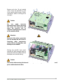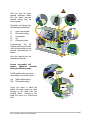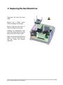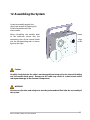
1
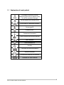
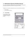
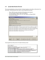
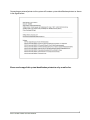
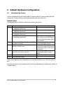
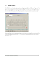
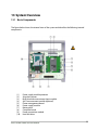
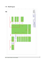
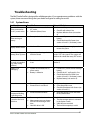
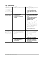
® BioZ Cardio Profile Service Manual 0197 Bio Z® Cardio Profile Service Manual, P15738-01 Document revision 1.0 Copyright © 2011 medis. Medizinische Messtechnik GmbH, Ilmenau, Germany BioZ Cardio Profile Service Manual iii BioZ Cardio Profile Service Manual iv Table of contents 1 1.1 Use of the Manual ............................................................................................................. 1 Explanation of used symbols ............................................................................................. 2 2 Contact Information ......................................................................................................... 3 3 Warnings and Cautions.................................................................................................... 3 4 4.1 4.2 Identification of System and Software Version ........................................................... 5 Device Number ................................................................................................................... 5 System Identification Printout ........................................................................................... 6 5 5.1 5.2 Default Hardware Configuration ................................................................................... 8 Hardware Info Screen ......................................................................................................... 8 HIPAA Password.................................................................................................................. 9 6 6.1 6.2 Blood Pressure Module Verification ............................................................................ 10 Pressure Transducer Verification ..................................................................................... 10 Leak Test ........................................................................................................................... 11 7 Touchscreen Calibration................................................................................................ 12 8 External Fuse Replacement ........................................................................................... 13 9 Battery Pack Replacement ............................................................................................ 14 10 Opening the System ....................................................................................................... 15 11 Replacing the Hard Disk Drive ...................................................................................... 18 12 Assembling the System ................................................................................................. 19 13 13.1 13.2 System Overview ............................................................................................................ 20 Basic Components ............................................................................................................ 20 Block Diagram ................................................................................................................... 21 14 14.1 14.2 14.3 14.4 14.5 Troubleshooting ............................................................................................................. 22 System Errors .................................................................................................................... 22 ICG/ECG Errors .................................................................................................................. 23 Blood Pressure Errors ........................................................................................................ 24 Hardware Info Screen - Failure Entries ............................................................................. 25 ICG Patient Cable Troubleshooting ................................................................................. 26 15 Parts List........................................................................................................................... 27 BioZ Cardio Profile Service Manual v BioZ Cardio Profile Service Manual vi 1 Use of the Manual Before repairing the system, read completely and carefully the instructions provided in this manual. If you do not understand any instructions or need additional information, please contact SonoSite Technical Support. The intended purpose of this manual is to help biomedical and/or clinical engineering personnel understand the functions of the system, to identify possible failures, and to guide in the repair. Before starting an analysis with regards of potential hardware problems, it is important to make certain that the system has been applied and operated in accordance with the instructions outlined in the user’s manual. Because of the complexity of the system and the numerous interactions between hardware and software components, when encoutering issues, we recommend contacting our service department prior to troubleshooting. We can assist to identify a possible failure and recommend the best and most efficient method to resolve the issue(s). For the best possible support, we recommend a short description of the issue(s) observed and all possible data from the system. (See Chapter 4: “Indentification of System and Software Version”). These conventions are used in this service manual: • • • • A WARNING describes precautions necessary to prevent injury or loss of life. A Caution describes precautions necessary to protect the product. Numbered steps must be performed in a specific order. Bulleted lists present information in list format but do not imply a sequence. BioZ Cardio Profile Service Manual 1 1.1 Explanation of used symbols Associated instructions provide important information to prevent injury, loss of life, or product damage Do not dispose with residual waste Device type BF, Defibrillator-proofed Device type BF Insulation class I Equipotential connector Caution, electrostatic sensitive devices USB-Connector Device Powered On Stand-By Connector for external keyboard Network connector Connector for external VGA-monitor Connector for serial interface BioZ Cardio Profile Service Manual 2 2 Contact Information Questions and comments are encouraged. SonoSite is interested in your feedback regarding the service manual. If you encounter difficulty with the system, use the information in this manual to help correct the problem. If the problem is not covered here, contact SonoSite Technical Support as follows: Technical Support (USA, Canada) 1-877-657-8118 Technical Support fax: 1-425-951-6700 Technical Support e-mail: [email protected] SonoSite website: www.sonosite.com (Select Support) 3 Warnings and Cautions For maximum safety, observe the following warnings and cautions: WARNING: The Bio Z® Cardio Profile is intended for use only within hospitals and other healthcare facilities (e.g. outpatient clinics, physician‘s office) that provide patient care. WARNING: To avoid the risk of an electric shock, this device must be connected to supply mains with protective earth. WARNING: Before opening the system, ensure that the system is switched “OFF” and the power cable is disconnected from the A.C. power mains. WARNING: The Bio Z® Cardio Profile must be connected by a three-wire power cable to an electrical outlet that has been properly installed and grounded. WARNING: The monitor is not protected against explosive substance. Do not use the Bio Z® Cardio profile in the presence of flammable anaesthetics or gases. WARNING: Before replacing the external fuse on the unit, disconnect the unit from the main power supply by pulling the plug out of the wall socket. WARNING: Before cleaning or disinfecting the measuring unit, disconnect the unit from the main power supply by pulling the plug out of the wall socket. WARNING: Do not modify any SonoSite products. Any modifications to the device will void the warranty. WARNING: Systems equipped with a battery must have the battery disconnected to avoid short circuit or contact with developed high voltage (up to 900V) which is present for the backlight inverter of the TFT display. BioZ Cardio Profile Service Manual 3 Caution: The system and/or software must be maintained, repaired, modified or altered only by persons authorized by medis/Sonosite or with prior approval by medis/SonoSite. Caution: Never gas-sterilize the patient cables. They are covered with a PVC shroud that can react with the gas-sterilization procedure to form a highly toxic ethyl nitrite. Sterilization in an autoclave, with ultrasound or gamma rays is also not permitted. Caution: Do not sterilize the Bio Z® Cardio Profile parts or accessories. Sterilizing the device or accessorries will void the warranty. Caution: Use only cables or components recommended by SonoSite to connect to the inputs and outputs of the monitor. Caution: Do not place the measuring unit on a surface which emits heat or expose it to direct sunlight. Do not cover the ventilation slits. Caution: Do not operate in bathrooms or other areas where water damage is possible. The Bio Z® Cardio Profile is not protected against splashing water. Caution: The Bio Z® Cardio Profile should be placed near the patient and fixed in such a way that the Bio Z® Cardio Profile cannot fall down if someone pulls on the cable. Caution: The Bio Z® Cardio Profile is protected against accidental ingress of liquids. If liquids ingress into the case, disconnect the monitor from the wall outlet. Caution: Do not expose the cables to mechanical or thermal impact. Avoid temperatures above 40 °C (100 °F). BioZ Cardio Profile Service Manual 4 4 Identification of System and Software Version This system may be delivered in different hardware and software configurations. In the event of a service request, it will be necessary to identify your system from our data base. To identify your system and the installed software version, we need the following information: 4.1 Device number System identification printout Device Number The device number is located on the backside of the system as indicated in the figure to the right. BioZ Cardio Profile Service Manual 5 4.2 System Identification Printout The system identification printout includes all relevant hardware and software information from the system. The following steps will create a system identification printout: • • • • Power “ON” the system and wait until the patient screen appears Press the “Options” button (a new screen appears) Press the “Hardware” button (the next screen appears, see figure below) Press the “Print” button The integrated strip chart printer will create the below printout. BioZ Cardio Profile Service Manual 6 Connecting an external printer to the system will create a system identification printout as shown in the figure below. Please send a copy of this system identification printout to us by e-mail or fax. BioZ Cardio Profile Service Manual 7 5 Default Hardware Configuration 5.1 Hardware Info Screen Connect all equipment to the Cardio Profile (ICG patient cable, ECG patient cable, NIBP cuff), connect to A.C. power, and go to the Hardware Info Screen (see section 4.2). Default entries The following entries should be stated in the Hardware Info Screen: Module Entries Battery AccuCtrl vx.xx: High current charging [+ additional information] AccuCtrl vx.xx: Accumulator loaded [+ additional information] AccuCtrl vx.xx: Accumulator available [+ additional information] AccuCtrl vx.xx: Initializing [+ additional information] ECG ICG ECG module ECG-Board Rx.x,Fw vx.xx; Build xx (cable connected) ICG Patient cable MeasureBox Rx.x Fw vx.xx; Build xxx SerialNo: xxxx NIBP NIBP-Device (SunTech: SW:LMx.xxx Saf:SM Vxxx HW:xxxx SN:xxxx Cycle xxx Pulse Printer Pulse extension NiccomoBoard Rx.x Thermal printer: ready Note The battery is being charged The battery is fully charged The battery is fully charged The battery is initializing (e.g. after startup), and should change to one of the entries above within some seconds The connected ECG board, version and cable is stated The connected ICG patient cable with Serial Number and Firmware is stated (see section 4.2 for more information) The connected NIBP module with Serial Number and Firmware is stated Optional. Typically not installed. There can be additional entries depending on the connected devices (e.g. USB-sticks, printers, etc.). Using the information in the Hardware Info Screen for troubleshooting is addressed in Section 14 Troubleshooting. BioZ Cardio Profile Service Manual 8 5.2 HIPAA Password The HIPAA Password configuration is performed by going to “Options” (F5), select “Password” and type in the selected password. Push the keyboard “Enter” () key to save the entry. The system will now require this password during each power “ON” or when the system is at idle for more than 5 minutes. The operator will not be prompted for this password during a patient study. To remove the password request, go to the password entry screen, leave the password entry line blank, and push the keyboard “Enter” (). The system will not prompt for a password request upon power “ON”. BioZ Cardio Profile Service Manual 9 6 Blood Pressure Module Verification If you have any doubts in the measured blood pressure values or you think the cuff is deflating too quickly, perform the following “Pressure Transducer Verification” or the “Leak Test” to check the function of the NIBP module. If the system fails in one of the performed tests, then the Cardio Profile and the blood pressure supplies must be sent to service for further testing. 6.1 Pressure Transducer Verification International standards for automated NIBP devices require that the maximum static pressure accuracy shall be ±3 mmHg. This is a stringent requirement and all test equipment must be in excellent working order to properly perform this test. It is important to verify the calibration before changing it. Although experience has shown that the transducers rarely need to be recalibrated the annually pressure verification is required. Equipment Calibrated Manometer Pneumatic "T" Adapters Volume (500 mL bottle or regular-sized cuff wrapped around a solid object is suggested) Hand Bulb Connection Tubing NOTE: Volume is added to the pneumatic system so that the user has more control of the pressure increments when using the hand bulb. If no volume is added, it is quite easy to cause unwanted overpressure errors using the hand bulb. Procedure 1. Connect a manometer, volume and the hand bulb to the Module using "T" adapters. 2. Inflate SLOWLY when adding pressure over 200 mmHg. 3. Apply various pressures (between 0 and 280 mmHg) to the Module with the hand bulb. Verify that the Module pressure is equal to the manometer pressure (±3 mmHg). If the Module pressure does not agree with the manometer pressure, then a calibration is required. Please contact our service support for assistance. BioZ Cardio Profile Service Manual 10 6.2 Leak Test International standards for automated NIBP devices require that air leakage within the pneumatic system must not exceed 6mmHg/minute. During manufacturing acceptable air leakage is less than 3 mmHg/minute when using a 500 mL rigid volume. Both of these pass criteria will not affect the performance or accuracy of the NIBP module so we suggest using the 6mmHg/minute pass criteria with a 500 mL rigid volume. Equipment Calibrated Manometer (optional may use pressure values supplied by NIBP module) Pneumatic "T" Adapters Volume (500 mL rigid bottle a blood pressure cuff is not recommended) Hand Bulb Connection Tubing Timer (i.e. Stop Watch) NOTE 1: Volume is added to the pneumatic system so that the user has more control of the pressure increments when using the hand bulb. If no volume is added, it is quite easy to cause unwanted overpressure errors using the hand bulb. Also, leak rates are exaggerated with extremely small volumes. NOTE 2: Blood pressure cuffs have large variations in size and materials which can cause large amounts of variation in the leak test results. To limit this effect, we strongly urge to only use a 500 mL rigid volume. Test Method 1. Connect a manometer, volume and the hand bulb to the Module using "T" adapters. 2. When using a hand bulb, make sure the exhaust valve is closed. 3. Increase the pressure to approximately 250 mmHg using the hand bulb or the pump on the module. It is difficult to slowly increase the pressure in the pneumatic system with the pump so a hand bulb is preferred. NOTE: When applying high pressures, take special care to increase the pressure at a rate that will not cause unwanted overpressure errors (300 mmHg). 4. Start the timer and wait 60 seconds for the pneumatic system to reach its pressure equilibrium point. All pneumatic systems have some degree of expansion and rebound which are affected by the several factors including volume, material types and material durometers. 5. After the waiting period, record the pneumatic pressure level (P1) and wait another 60 seconds and record the pneumatic pressure level again (P2). NOTE: Safety circuitry on the module only allows the pressure in the pneumatic system to remain above 10 mmHg for 180 seconds. When this safety time limit is exceeded, the valves will open and the module will be disabled. To reset the NIBP module, it must have the power cycled or it needs to be set to its sleep mode and awakened. Not all NIBP module customers have the ability to use the sleep mode. 6. Open the hand bulb valve to exhaust the air from the pneumatic system. 7. Subtract P2 from P1 and this is the leak rate per minute. BioZ Cardio Profile Service Manual 11 7 Touchscreen Calibration Recalibration of the touch screen may be necessary when: 1. Pressing a touchscreen button does not activate that function, but the 'click' sound is heard. 2. Pressing a touchscreen button activates a nearby function. To calibrate the touchscreen, please perform the following steps: 1. Power “OFF” then power “ON” the system. (The calibration function can only be performed on a freshly restarted system.) 2. When the patient data screen is displayed, touch the screen on any random blank area and continue pressing the screen (for approximately 5 seconds) until the calibration menu is displayed (see next picture). 3. The calibration menu will prompt you to touch every corner of the screen display. The touched positions will be saved as the calibrated data and now the touchscreen operation will respond properly to the keystrokes entries. BioZ Cardio Profile Service Manual 12 8 External Fuse Replacement The system is protected by 2 fuses which may be removed as shown in the figure to the right. Open the fuse compartment using a screw driver. Use care to not damage the case. WARNING Make sure the replacement fuse is of the same type and value. Use of a substitute fuse type or value may result in safety risks or damage to the system. (1.0 Amp Slo-Blo. See the Parts List for more information) If the replacement fuses continue to fail, then the system requires inspection by an authorized service department. BioZ Cardio Profile Service Manual 13 9 Battery Pack Replacement The battery pack can be disconnected or replaced by opening the battery compartment cover located on the bottom of the system. This compartment cover entry allows access to the battery without having to remove the system enclosure. This procedure requires the removal of 4 Philips screws securing the battery access cover. Access into the battery compartment will allow the battery cable to be disconnected or the removal/replacement of the battery pack (1). Battery pack replacement requires performing the above steps in the reverse order. Upon battery pack reinstallation, ensure that the battery cable is connected and routed properly as to not be pinched or cut by the internal hardware or the battery compartment cover. Secure this cover with the 4 screws removed earlier. BioZ Cardio Profile Service Manual 14 10 Opening the System WARNING Turn “OFF” the power switch and disconnect the A.C. power cord from the system. Place the system on its front side as shown in the figure to the right and use a soft underlay so that the display/touch screen will not be damaged. Before you open the system enclosure, it is important that you have disconnected and removed the battery pack as previously described. Failure to do so will result in the battery pack falling down and/or creating an electrical short. Remove the 4 middle screws of the system back panel. Now remove the remaining 13 back panel screws. The enclosure is now loose and will allow movement upward to clear the system. (See the figure to the right). BioZ Cardio Profile Service Manual 15 Remove only the 10 red marked screws from the backside of the inner metallic shield using a Philips screwdriver. (Refer to the figure to the right). Caution Do not apply excessive downward force while removing the screws. Too much force will cause the press-fit nut to separate and drop from its mount on the metallic shield. Attention Removal of the other screws that are not marked red will result in loosening other components such as the fan, loudspeaker, and blood pressure module. Moving the metallic inner panel upward will allow enough space to disconnect electrical cables and the blood pressure module tubing. Caution Use caution when moving the internal metallic panel as damage could result to the internal parts and the electrical cables. BioZ Cardio Profile Service Manual 16 After the case has been opened, electronic cables and the blood pressure module tubing may be disconnected. The cables and tubing have the following attachments: (1) (2) (3) (4) (5) Valve control cable BP module tubing Loudspeaker Fan BP module cable Disconnecting the BP module cable requires both sides of the connector to be pressed simultaneously to release. Now the backside can be completely removed. System reassembly will require additional attention during the following steps: The BP module tubing must be reinstalled on the correct valves: (2a) (2b) NIBP module tubing PW module tubing Figure (4a) shows in detail the proper fan cable routing to avoid damage to this cable from the metallic shield. Damage to this cable may result in a short-circuit fault. BioZ Cardio Profile Service Manual 17 11 Replacing the Hard Disk Drive Disconnect the hard disk drive cable. Remove the 3 Philips screws shown in the figure to the right. Remove the hard disk drive as show in the figure to the right. Installing the replacement hard disk drive requires performing the above steps in the reverse order. Make sure that the hard disk drive cable is correctly connected and that the screws are securely tightened. BioZ Cardio Profile Service Manual 18 12 Assembling the System System reassembly requires the steps from Section 10 (Opening the System) be performed in the reverse order. When reinstalling the metallic back to the enclosure, ensure that the connecting slots of the internal shield into the corresponding tabs as shown figure to the right. panel align in the Caution Carefully check that the fan cable is not damaged from being cut by the internal shielding and the metallic back panel. Damage to this cable may result in a short-circuit and/or subsequent damage to the electronic components. WARNING All necessary function and safety tests must be performed and filed after the reassembly of this system. BioZ Cardio Profile Service Manual 19 13 System Overview 13.1 Basic Components The figure below shows the internal view of the system and identifies the following internal components: (1) (2) (3) (4) (5) (6) (7) (8) (9) (10) Power supply module protector Strip chart printer Multi-channel measurement Input module SpO2 measurement module (optional) Power management board Power supply module Battery pack Computer board Power connection module Hard disk drive BioZ Cardio Profile Service Manual 20 13.2 Block Diagram 14 BioZ Cardio Profile Service Manual 21 Troubleshooting The BioZ Cardio Profile is designed for reliable operation. If you experience any problems with the system, there are several things that you should verify prior to calling for service. 14.1 System Errors Problem(s) Possible Causes Potential Solutions System not connected to live A.C. mains Defective (blown) fuses Connect A.C. power cord Check if wall socket is live Replace defective fuses (see section 8) System does not start when running on battery Battery is drained or defective Connect A.C. power cord to recharge battery Check Hardware Info Screen (see section 4.2 and 5.1) for battery status System starts but display remains black Hardware failure Unusually long startup (boot up) time System is performing a hard disk drive check Wait, until the check is performed. Do not power “OFF” the system. The system will perform this check after every 20th restart. Touch screen does not work as intended (e.g. select wrong function) Battery is not recharging Touch screen has calibration issue Perform the touch screen calibration (see section 7) System not connected to A.C. power mains Battery is defective System fails to start when connected to the A.C. power mains Connect A.C. power supply cord and restart the system Connect A.C. power cord to recharge battery Check if the A.C. wall supply is live Check Hardware Info Screen (see section 4.2 and 5.1) for battery status Replace battery (see section 9) Printer does not work Printer paper is empty Printer cover is not closed Replace the paper Close the printer cover Check the Hardware Info Screen (see section 4.2 and 5.1) Printer makes an unexpected clicking or grinding noise No measurement data is stored to the hard disk drive Printer mechanical failure Open the printer’s cover and check for any obstructions Data storage is deactivated Measurement was too short or did not include enough valid data Hard disk drive is full Check if: The data storage option is activated in the Option screen Valid data was recorded The hard drive capacity is at 0% BioZ Cardio Profile Service Manual 22 14.2 ICG/ECG Errors Problem(s) Possible Causes An ICG measure ICG patient cable is not ment cannot be connected started. (ICG button is not available to select as exam type). ECG or ICG has excessive artifact Patient movement Sensors are dry Sensors are not properly applied Potential Solutions Connect the ICG patient cable () to the system Check the Hardware Info Screen (see section 4.2 and 5.1) No heart rate is measured during ICG measurement ECG cable is connected to the system, but not to the patient ECG vector cannot be measured with the ICG patient cable BioZ Cardio Profile Service Manual Check the ICG patient cable () LEDs for details (see section 14.5) Prep the patient’s skin with soap and water before applying sensors Be sure patient is laying still (motion such as coughing and talking will produce instability in the waveform) Remove any jewelry that may interfere with the lead wires Attach fresh sensors Reposition the sensors Remove the ECG cable from the system and restart the measurement or Connect ECG patient cable to the patient Invert the ECG waveform Connect the ECG patient cable to the system and at the patient, and restart the measurement 23 14.3 Blood Pressure Errors Problem(s) Weak or No Oscillometric Signal Artifact / Erratic Oscillometric Signal Exceeded Measurement Time Limit Pneumatic Blockage Possible Causes Cuff is in wrong position Cuff is loose on patient’s arm Excessive clothing between cuff and patient’s arm Cuff is the wrong size Patient is not motionless and relaxing their arm Patient has weak and/or low pulse Hose, cuff, and/or fittings are blocked Hose or cuff is crimped and/or folded Hose, cuff, and/or fittings are blocked Hose or cuff is crimped and/or folded Hose, cuff, and/or fittings have a leak Cuff is loose Hose, cuff or fittings are not connected properly Check cuff connection Replace hose, cuff and/or fittings Input error Communication error Hardware error Check, if the measurement was started properly Check the Hardware Info Screen for the NIBP module status (see section 4.2 and 5.1) Cuff Overpressure Inflate Timeout, Air leak or Loose Cuff Blood pressure measurement does not start Potential Solutions Reapply Cuff and retake BP ensuring that: The arrow on the cuff is located over the patient’s artery just above the elbow joint The cuff is wrapped snugly There isn’t excess clothing under the cuff The size is correct for the patient’s arm circumference The patient is motionless with their arm relaxed during the measurement cycle BioZ Cardio Profile Service Manual Clear hose, cuff or fittings of any blockage Replace hose and/or cuff Clear hose, cuff or fittings of any blockage Replace hose and/or cuff 24 14.4 Hardware Info Screen - Failure Entries The following entries can be an indicator of a hardware failure. Follow the information in the “Note” section. If any “Entries” remain for the corresponding module, then the system with its equipment must be sent to service for further testing. Module Entries Battery AccuCtrl vx.xx: Running on accumulator-power [+ additional information] AccuCtrl vx.xx: waiting [+ additional information] AccuCtrl vx.xx: No accumulator found [+ additional information] ICG ECG AccuCtrl vx.xx: Accumulator possibly defective! [+ additional information] Patient cable: Waiting… ECG module ECG-Board Rx.x,Fw vx.xx; Build xx (cable disconnected!) BioZ Cardio Profile Service Manual Note System is running on battery even though it is connect to the wall supply. Check if: A.C. power cord is properly connected A.C. source is live Blown fuses Defective A.C. power cord The battery control board was not found No battery is connected to the system Check if: Battery is properly connected to the system (see section 9 for details) The battery is defective and should be replaced. See section 9 for details. Searching for ICG patient cable even though it is connected. Check if: ICG cable is properly connected to the system See section 14.5 for more information. Searching for ECG patient cable even though it is connected Check if: ECG cable is properly connected to the system 25 14.5 ICG Patient Cable Troubleshooting During the ICG mode of operation, the green LED on the ICG patient cable () will be constantly illuminated while the red LED will remain unlighted. The Cardio Profile ICG waveform should be free of noise and artifacts. In case of a problem, check the LEDs on the patient cable using the chart below: Green Orange ○ ○ The electronic part of the patient cable is not connected with the power supply; cable is disconnected or the system is switched off ☼ ○ Patient cable is ready to use, but the measurement has not been started ● ○ Measurement is running; sensor contact is good ☼ Bad contact between sensors and patient: at least one lead wire is disconnected or not properly fixed; sensors are too dry (eventually new sensors are necessary) ● ● Insufficient contact between sensors and patient: at least one lead wire is disconnected or not properly fixed; sensors are too dry (new sensors are necessary) ○ ☼ Patient cable has power but the software cannot access the cable; software has not been started or is not ready for measurement ● Legend: Description of function ○ LED off BioZ Cardio Profile Service Manual ☼ LED flashing ● LED on 26 15 Parts List Service Exchange Unit, BioZ Cardio Profile Service Exchange Unit, ICG/ECG Cable Service Kit, Replacement Fasteners, BioZ Cardio Profile Stand Service Kit, Replacement Casters, BioZ Cardio Profile Stand Battery Pack, BioZ Cardio Profile Cable, Patient, ICG/ECG Cable, Patient, ECG Cuff, Adult, NIBP, (23-33 cm) Cuff, Adult, NIBP, Large, (31-40 cm) Cuff, Adult, NIBP, Small, (17-25 cm) Cord set, 10 Amp, C13 Connector, Hosp. Grade, N. Amer. Hose, Air, NIBP Kit, Basket, BioZ Cardio Profile Basic Stand Monitor Fixation Clamp Paper, Thermal Printer (10 pack) Stand, Basic, BioZ Profile Systems System Mount, Basic Stand, BioZ Cardio Profile Fuse, 1.0 A, Slo-Blo, 250 VAC, 5 X 20 MM BioZ Cardio Profile Service Manual P15399-01 P15400-01 P15477-01 P15478-01 P15086-01 P15002-01 P15003-01 P15006-01 P15480-01 P15481-01 P00848-01 P15007-01 P15065-01 P15482-01 P15009-01 P15062-01 P15064-01 P15787-01 27 P15738-01 *P15738-01*