1
BioZ.com®
Operator's Manual
Part # 1095601
Revision E, November 2001
Cardio Dynamics
INTERNATIONAL CORPORATION
6175 Nancy Ridge Drive
San Diego, California 92121 USA
(800)-778-4825 (858)-535-0202
Fax (858)-535-0055
European Authorized Representative:
Donawa Italia Sri
Via Fonte di Fauno, 22
00153 Rome, Italy
CardioDynamics International Corporation
This document contains confidential information that
belongs to CardioDynamics International Corporation.
No part of this document may be transmitted, reproduced,
used, or disclosed outside of the receiving organization without
the written consent of CardioDynamics International Corporation.
CardioDynamics'" ,BioZ.com® and BioZtect™
are trademarked names protected by law.
TABLE OF CONTENTS
TABLE OF CONTENTS
1
INTRODUCTION
1.1 Theoretical Concepts
1
1
2
WARNINGS AND PRECAUTIONS
2.1 General Warnings
2.2 Precautions
2.3 Indications
2.4 Contraindications
3
3
3
4
4
3
SYSTEM FEATURES
3.1 Standard Features
3.2 Optional Features
4
GETTING STARTED
4.1 General System Overview
4.2 User Interface (Symbol Key)
4.2.1 Softkeys
4.2.2 Hardkeys
4.2.3 LED Indicators
4.2.4 External Connections
'"
5
5
6
7
7
8
8
8
12
14
5
QUICK-START INSTRUCTIONS
17
6
BIOZ.COM® TUTORIAL
6.1 Startup
6.2 Patient Data Entry
6.3 Patient Monitoring (Demo Mode)
'"
6.4 Printing
6.5 Reviewing Patient Records
6.6 Exiting a Monitoring Session
19
19
20
25
34
35
35
7
"LIVE" PATIENT MONITORING
7.1 Patient Preparation
7.1.1 ICG Sensors
7.1.2 Skin Preparation
7.1.3 ICG Sensor Application
7.2 Patient Monitoring
7.2.1 Blood Pressure without Starting ICG Monitoring Session
7.2.2 ICG Monitoring Session
7.2.3 Softkeys
7.2.4 Patient Data Entry Fields
7.2.5 Patient Monitoring Screens
37
37
37
37
37
40
.40
41
41
41
51
8.
DETAILED DESCRIPrION
8.1. Welcome Screen
8.1.1 System Set-up
8.1.2 Configure Screens
8.1.3 Update Patient Information
Bioz'com® Operator's Manual
61
61
62
78
84
-i-
CardioDynamics International Corporation
8.2 Patient Records Management.
8.2.1 Adding a New Patient.
8.2.2 Add New Data to Previous Patient Record
8.2.3 Review or Delete Patient Records
8.3 Printing Information
8.3.1 Print Screen Report
8.3.2 Hemodynamic Summary Report
8.3.3 Hemodynamic Trend Report
8.3.4 Hemodynamic Status Report
9
85
85
85
85
89
89
89
90
90
TROUBLESHOOTING .........................................................................••............•.........••........•.•. 93
93
94
94
9.1 Signal Acquisition Error
9.2 Low Battery
9.3 Printing Errors
10 NOMINAL SPECIFICATIONS
97
11 MAINTENANCE
11.1 Cleaning
11.2 Patient Cable
99
99
99
12 Z CARE® STANDARD WARRANTY
101
13 SOFTWARE LICENSE AGREEMENT
103
14 APPENDIX A. GLOSSARY OF TERMS
105
15 APPENDIX B. PRINT SCREEN REPORT
109
16 APPENDIX C. HEMODYNAMIC SUMMARY REPORT
111
17 APPENDIX D. HEMODYNAMIC TREND REPORT
113
18 APPENDIX E. HEMODYNAMIC STATUS REPORT
115
19 INDEX
117
- II -
BioZ.com® Operator's Manual
TABLE OF FIGURES
TABLE OF FIGURES
Figure 1. Text Entry Screen ...........................................................•...........•........................................•.8
Figure 2. BioZ.com® Welcome Screen..•..•.•.•..•....•.......•....•..........••.•••.••••.•••..•••.•••.•••••••.•••.•••••..••..••...••19
Figure 3. Patient Data. Entry Screen .....•....•....•..•.•....•.......•................•..•......•..••..•.••..•••..••..•..•............20
Figure 4. Patient Data Entry Screen ................................................•...............•..........•...•..•.............•.21
Figure 5. Patient Data Entry Screen ..•....•.•.........................•..........•.....•......•..•...•..•..••...•...•......••..•.•..•21
Figure 6. Patient Data Entry Screen .....•.•....•.....•........••...........................•..•.............•.......•..........•..•.•22
Figure 7. Patient Data Entry Screen •.......•..•...•.........•..•.....................•................•.•......................•.••..22
Figure 8. Patient Data Entry Screen ..................•....•............•.......•............................................•••.•....23
Figure 9. Manual Blood. Pressure Entry Screen........•....•...................••....•...............................••.•.....23
Figure 10. Patient Data Entry Screen ...•...........................................•.••.....•...•..•.....••...•..•......•...........24
Figure 11. Patient Data Entry Screen .•..........................................•...•.••.•......••........•....•..••.....••.••.•....25
Figure 12. Monitoring Screen (Demo Mod.e) ..........•.............................•..............................•.......•.....26
Figure 13. BioZ.com® User Menu Screen •.•.•..•.•....•..............•.......•........•..•.........•..•......................•.•..27
Figure 14. Password Entry Screen ..............•......•..•............................................•...••....••....................27
Figure 15. Screen Configuration Menu...•.•..•.•.........................................•..••............•...............•........28
Figure 16. Monitoring Screen Configuration (1) •.•..•.•..•.•..•......•..•..•..•..•..•..••..••..•.••.•••.••...•...•..••.•..•..28
Figure 17. Monitoring Screen Configuration (2) ...•.•..•.•..•............•.•...•.....•..•...•..•..••..••.••..••...••.••.•••..29
Figure 18. Hemod.ynamic Parameter Menu (1)....•..•.•.•....•..•............•...•.••.•...•..••.••.•••..•..•..••....•..•..••••29
Figure 19. Monitoring Screen Cell Configuration Screen..........•..•..••.•..•..•..•...............................•.••30
Figure 20. Screen Configuration Menu Screen
30
Figure 21. User Menu Screen.............•..............•...............................•.........•....••........................•..•.....31
Figure 22. Patient Monitoring Screen (Demo Mode, Re-Configured) ..•....•......•..•.......•..•.......•..•....31
Figure 23. Diagnostic Screen (Demo Mode) ..........•.............................................•..............•..............32
Figure 24. Therapeutic Screen (Demo Mode)......•............................................................................•32
Figure 25. Trend Screen (Demo Mode) .......................................•.........................•..........•.......•.........33
Figure 26. Waveform Screen (Demo Mode) ..•.•..•................................•..•.••.....•....•...•...•..•.............•.••33
34
Figure 27. Print Option Screen (Demo Mode, Re-Configured)
Figure 28. BioZ.com® Welcome Screen.•.....................•......................•..........•...............•..............•.•...35
Figure 29. Impedance Cardiography Sensor Placement Diagram•..•....•.................................•.......39
Figure 30. Independent Blood Pressure Screen .......................................•..................•.....................40
Figure 31. Blood Pressure Measurement Results Screen .......................•....••.•.....•..•...•....................40
Figure 32. Patient Data Entry Screen ..............•.•.........•..................................•..•.••......•.........•.........•.41
Figure 33. Patient Data Entry Screen ..•.•..•.•..•...................•.•................•.•..•.......................................42
Figure 34. Text Entry Screen ..•.•..••.•..•..•...........................•...............•.......•.........................................42
Figure 35. Patient Data Entry Screen ...•........................•..................•.....•.......•....................•.............43
Figure 36. Patient Data Entry Screen ...........•..•.........•.........•.......•..•.....•..•..•..•..•..•..••..••.••..•...••..••.•.•..44
Figure 37. Patient Data Entry Screen ...........................•...............•..•.....•...........................................45
Figure 38. Patient Data Entry Screen .....•..............•......................................................................•.•••45
Figure 39. Patient Data Entry Screen .............................•....•.......•...................•........••..••.........••..•.•...46
Figure 40. Manual Blood Pressure Entry Screen.................•.....................................•......................48
Figure 41. Blood Pressure Out of Range Screen .....................................................................•....••...48
Figure 42. Patient Data Entry Screen ..•..•...............•......•.............................•.......•....••..•....................49
Figure 43. Patient Data Entry Screen ...•.............................................•.............•.............•..••..••..•..•..•.49
Figure 44. Patient Data Entry Screen ...............................................................................•..•.........•...50
Figure 45. Data Out of Range Screen...•...................................•.........•............•...•..•......••.............•..•..50
Figure 46. Monitoring Screen (Live Mode) .........•.................................•......•......•..•...•...•..•...•...•....•..52
BioZ.com® Operator's Manual
- III -
CardioDynamics International Corporation
Figure 47. Manual Blood Pressure Entry Screen (Live Mode)............................•...........•..........•....53
Figure 48. Data Out of Range Screen.............•...................................................................•..•...•..•..•..54
Figure 49. Diagnostic Screen (Live Mode) .......•.......••.....•..............••........•...•..••....•...•..•...........•.....•...54
Figure 50. Therapeutic Screen (Live Mode) ...•..........•.•........•......•.•.•.....•....•..••.•..•.••...•...•....••••..•..•.••.56
Figure 51. Trend Screen (Live Mode) .•.••••.•.....••••...•..•...•.•.............•••..•...•••.......•....•.•••..•..••.•.••...•.••..••57
Figure 52. Expandable Trend Screen (Live Mode) ............................•........••..•..••••....•••..•.••.••..••..••••.58
Figure 53. Trend Screen Set-Up Screen (Live Mode) .......................•.......•..•..•....•...•..••.••....•...••..•.••.58
Figure 54. Waveform Screen (Live Mode) .....•.•.•....•.••................•....•.•.......•..•..•....•..•••••...•.•..•........••.•59
Figure 55. Welcome Screen ..•..•..•.•.........•.•......•...•.•......•.•......•.•.........•......•..........•..•..•..••.•...••.•..•••.•.•.•.61
Figure 56. BioZ.com® User Menu Screen .•••.................•.................•..........•.......•........•..•..•.........•......62
Figure 57. BioZ.com® Set-Up Menu Screen•......•••••.....•..•...•••......••.....••••.....•••.•...••••.•••••••....•.•••...•••..•63
Figure 58. Alarm Status Screen ..••.•••....•.••..•..•...•........•.•.•.....•..•.•....•....••......•..•.•.....•.••.....•.......•..•.••.•.•64
Figure 59. Alarm Limit Set-Point Screen ..•..........•.•........•.•.....••.•...••••.....•••....•.•••••..•.•••..•..•••....••••.•.••65
Figure 60. Alarm Reset Time Delay Screen...•.•••........•........•.•.•....•.•.•.••......•.•...•..•.••..••.•••.....•••••.••••.•.66
Figure 61. Password Entry Screen .•.•..•••••.•.•..•••.•......•••...•.•••.....••....•.•••......••..•....••.•..••••••..•..•...•..••...••67
Figure 62. Normal Range Gender Screen ............•...•....•.•.•..........•......•..•.•..•....••.•.•..••.•.••..••••..•.•...••.•.68
Figure 63. Normal Range Menu Screen (1) .............•........•.•.•..........•..•.........•.......•..•..••...•..•...•.....••.•.68
Figure 64. Normal Range Menu Screen (2) .••••......•.•.•.•.•..•.•.•••.•....•....•.••••.•.•...•.•.•...••••...•..••..•.•.•..•.••.69
Figure 65. System Default Menu Screen •.•.••...•.......•......•.•...................•..•............•..••.••.•••••..•....•..•..•••70
Figure 66. BioZ.com® System Set-Up Menu (Screen 2)..............•.....•......•.......•....••..•..•.••..•...••..•.••..•72
Figure 67. Events List Screen•.•....•..•.•.•..•.•.•.•...•....•..........•..........•.•.........•.........••••.....••••..•..••.•...••••..•.•72
Figure 68. Password Entry Screen ..•.••.•.•.....................•.................•....•......••......•..••••.....••••......•....••.••73
Figure 69. New Password Entry Screen ••...•.•........•.•......•...•.••............•.••.•.....••..•....••..•..•.••..•..••..•.••.••.74
Figure 70. New Password Re-Confirmation Entry Screen.....•....•.•....•..•...•..•.•..•..•.•••.••..••••.•...••.•..•.•74
Figure 71. New Password Verification Screen ....•••...•.•..•.•.•....•.•.•..•.•....•...•..•..•..••.•..•..••.•.••.....•...••••.•75
Figure 72. System Set-Up Menu •••.•...•..•....•••••.•.••...•..••........•..•......••....•.•....•.••••..•.••••...•..••.•..•..••..•.••..•75
Figure 73. Facility Name Entry Screen •.•.•....•.•......•...•............•....•.•.•....•.•....•..•....•.••.•••..•....•...•....••..•.76
Figure 74. Language Selection Screen....••••.....•••.....•...................•.............•................••.•..•.•....•..•••..•..77
Figure 75. Custom Status Report Selection Screen (1)........•......•.•••....•...........•....•..•...••••..•..•.••.....•••.78
Figure 76. Custom Status Report Selection Screen (2)..........•..........•...•..•.•..•....•....•...••••..•..•...•....••...78
Figure 77. BioZ.com® Screen Configuration Menu Screen.•.....•.....•.•.•.••.•.....•...•.••..••.•••.•.•...•..•...••••79
Figure 78. Patient Monitoring Screen Cell Configuration Menu (1)
80
Figure 79. Patient Diagnostic Screen Cell Configuration Menu (1)
81
Figure 80. Hemodynamic Parameter Set-Up Menu (1).........•.....••...•....•.....••.....••.•..••••..•.•••.•....•••....81
Figure 81. Trend Screen Cell Configuration Menu Screen.......•....•.•....•.•...•...•..••.•..••.•....••..••..••......82
Figure 82. Waveform Screen Cell Configuration Menu Screen
83
Figure 83. Patient Data Entry Confirmation Screen .....•........•...•..•.•..•.•••......•.•..•..••..•..••••.....•••..•.•••.84
Figure 84. Patient Data Entry Exit Screen .....•.•........•...........................•.......•.....••.••..•..•..•..•.••••..•••.•.85
Figure 85. Patient Record Review Screen (1) .....•........•.•.......................•...........•.•..••••.•...•••.•.•..•.••.•..•86
Figure 86. Patient Record Review Screen (2) ....•.....•.....•..........•....•....•..........•........•••••..•.••••..•.•.....•.••86
Figure 87. Patient Record Review Screen (3) .•......•......•......•.•.....••..•.•••••.•...•.•.....•...•.•••••.•.•..••••..••••.•.87
Figure 88. Patient Record Review Monitor Screen (4)................•..........••....•..•.....•..•••..•....•...•..•..•.••87
Figure 89. Poor ECGlImpedance Waveform Error Screen ....••..•.••.•..•.••..•..•..•..•..•.••.•..•.•..•....••••..•.•93
Figure 90. Low battery Warning Screen•.•....•...............•............•.•..•..••...••.•......•••••.•.•.••••..•••••...••••.••••94
- iv -
BioZ.com® Operator's Manual
Error! Reference source not found.
NOTE: Before using the BioZ.com®, carefully and completely read the instructions in this manual. If
you do not understand the instructions or need additional information, contact CardioDynamics
International Corporation (CDIC) at the address listed on page one of this manual.
1
INTRODUCTION
The BioZ.com® is an innovative noninvasive impedance cardiography (ICG) device that provides
hemodynamic;arameters based on the measurement of thoracic electrical bioimpedance. Specifically,
the BioZ.com allows for assessment of a patient's hemodynamic status and ventricular function by
determining twelve (12) hemodynamic parameters as well as four (4) indexed parameters. In addition,
the BioZ.com® allows the operator to:
•
Observe trends in the patient's status
•
Measure Blood Pressure Independently with Optional integrated Blood Pressure monitor
•
View, store, and review the collected data and/or waveforms
•
Print reports of the hemodynamic parameters with the date and time annotated accordingly
•
CopylDownload files to a PC
•
Utilize security precautions - Password protection for system configuration
1.1
Theoretical Concepts
Note: The initial use of thoracic electrical bioimpedance was supported by impedance cardiography
and plethysmography assessments. Today, many terms are used interchangeably when discussing
impedance cardiography: Thoracic electrical bioimpedance (TEB), thoracic electrical impedance, and
electrical bioimpedance. In this manual, the term impedance cardiography or leG will be used.
ICG is a technology that quantifies the mechanical activity of the heart (blood flow) as opposed to its
electrical activity (ECG). The fundamental theoretical basis of ICG involves direct measurement of
base impedance, velocity index, acceleration index, pre-ejection period, ventricular ejection time, and
heart rate. These measurements are then used to calculate additional hemodynamic parameters.
The application of ICG to determine hemodynamic parameters is based on the following principles:
Biological tissues, such as muscle, bone, fat and blood, all have different electrical properties. Of
these tissues, blood is the most electrically conductive. Since arterial blood flow is pulsatile and
arterial vessel walls are compliant, pulsatile changes in blood volume occur in the thoracic arterial
system, predominantly in the aorta, as a result of ventricular function. This change in blood volume
results in a change in the electrical conductivity and thus the impedance of the thorax to electrical
current. Changes in the electrical impedance of the thorax are primarily due to changes in the velocity
and volume of the blood in the aorta.
The BioZ.com® measures this change in impedance by injecting a high frequency (60 kHz Minimum),
low amplitude (4.0 rnA rms Maximum) alternating electrical current through the thorax between a pair
of sensors placed on the neck and another pair placed on the mid-axillary line at the xiphoid process
level. Use of a high frequency current eliminates the possibility of interference with bioelectrical
BioZ.com® Operator's Manual
- 1
CardioDynamics International Corporation
activity of the heart and brain. Additionally, as the skin-to-sensor impedance is very low at high
frequency, there are no thermal effects to tissue, thus no sensation to the patient.
By detecting and measuring the change in thoracic impedance as a function of time, the BioZ.com® is
able to noninvasively calculate stroke volume, cardiac output and many other hemodynamic
parameters. In comparison, thermodilution invasively measures the change in temperature over a
change in time in order to calculate stroke volume and cardiac output.
- 2-
BioZ.com@ Operator's Manual
WARNINGS AND PRECAUTIONS
2
WARNINGS AND PRECAUTIONS
2.1
General Warnings
• As a Class IIa, Type BF device under the Medical Device Directive, the BioZ.com® is
not specifically intended to monitor variations in cardiac performance that could
result in immediate danger to the patient.
• Caution: Federal law restricts this device to use by or on the order of a physician.
• Explosive Hazard: Do not use in the presence of flammable anesthetics or gases.
• Sensors are to be placed externally on the skin only and are not for direct cardiac
application.
• The conductive gel of the sensors should not contact any other conductive materials
during patient monitoring.
• For safe and proper operation this device is to be connected to a grounded receptacle.
The Equipotential Bonding Receptacle (per DIN 42801) is provided for users who wish
to connect the BioZ.com® device to the institution's equipotential system.
• To maintain compliance with Electromagnetic Compatibility (EMC) standards, if
your device has an external Ferrite Core, it must remain attached to the patient cable
(and keyboard cable when connected to the BioZ.com~ at all times.
• The patient cables specified and included with the BioZ.com® are designed specifically
for protection against the effects of cardiac defibrillators and radio-surgery
equipment. Do not use any other type of patient cable with this device.
• Disposal of this product and/or any of its accessories shall be in accordance with any
and all local regulations.
• The printer and serial output and input ports on the back of the BioZ.com should only
be connected to peripheral devices that meet the requirements of Safety Standard IEC
950. Consult the manufacturer or the user's manual of the peripheral device to verify
that it complies with IEC 950.
• Caution! When monitoring patients with indwelling catheters, the printer must be
used with a HospitallMedical grade power supply. Should you have questions or
require clarification, please contact CardioDynamics Technical Service for more
information.
2.2
Precautions
Impedance Cardiography (ICG) is a theoretical model of blood flow movement and is subject to
inaccuracies in cases where the model does not fit a particular patient's clinical circumstances.
Conditions that may limit the accuracy of the data are listed below:
• Septic shock
• Aortic valve regurgitation
Bioz'com® Operator's Manual
-3
CardioDynamics International Corporation
• Severe hypertension (MAP> 130 mrnHg)
• Patient heights measuring below 48" (120 ern) or above 90" (230 em)
• Patient weights measuring less than 67 lbs. (30 kg) or greater than 341 lbs. (155 kg)
• Patient Movement
•
Aortic Balloon Pump
Observe the following considerations when using the BioZ.com®:
• During open chest surgery, the BioZ.com® may produce inaccurate values because of the change in
the normal pattern of blood flow and/or the electrical current flow through the chest cavity. In
addition, during post-operative recovery monitoring, patient shivering and motion may produce
excessive artifacts that may affect the accuracy of the BioZ.com®.
• Signal interference caused by other equipment may occur if cables and/or power cords of the
BioZ.com® and other equipment cross over each other.
• The BioZ.com® should not be used concurrently on patients with Minute Ventilation pacemakers
when the MV sensor function is activated.
2.3
Indications
• The Bio'Z.com" is designed for use with an adult in a resting position. The BioZ.com® and its
components are not designed, sold, or intended for use except as described in this document.
• For hygienic purposes, single use patient sensors are specified when using this device.
• The BioZ.com® is a FDA Class IT device.
• The blood pressure cuff provided with the BioZ.com® is non-conductive thus assuring no risk of
burning the patient during radio surgical procedures such as electrocautery.
• The patient cable circuitry affords a high degree of patient isolation from potential ground faults.
2.4
Contraindications
None known.
- 4·
BioZ.com® Operator's Manual
GETTING STARTED
3
SYSTEM FEATURES
3.1
Standard Features
The BioZ.com® interfaces with:
•
Printers utilizing the Hewlett Packard PCL3 (and more recent) communication protocol
•
External Keyboard
•
IBM compatible PC's (with specialized software installed)
The BioZcom'" measures the following parameters:
•
Thoracic Fluid Content (TFC): the inverse of the thoracic base impedance
•
Indices of Contractility: reported as Acceleration Index (ACn and Velocity Index (Vl)
•
Pre-Ejection Period (PEP)
•
Left Ventricular Ejection Time (LVET)
•
Heart Rate (HR)
•
Blood Pressure (if optional module purchased)
The BioZ.com® calculates the following parameters:
•
Cardiac Output (CO)
•
Stroke Volume (SV)
•
Systemic Vascular Resistance (SVR): also reported as Afterload
•
Left Cardiac Work (LCW)
•
Systolic Time Ratio (STR)
Several of the above parameters are indexed with reference to body surface area (BSA) to give indexed
parameters. The BioZ.com® calculates the following indexed parameters:
•
Cardiac Index (Cl)
•
Stroke Index (Sl)
•
Systemic Vascular Resistance Index (SVRI)
•
Left Cardiac Work Index (LCWn
BioZ.com® Operator's Manual
-5
CardioDynamics International Corporation
3.2
Optional Features
The BioZ.com® is available with the following optional features:
•
Internal Battery Power
In the event that AC power becomes unavailable, the Bioz.com" will continue to operate for up
to 30 minutes. An LED signal status light indicates the strength of the battery and a Charging
LED indicates when the battery is being charged.
•
Built-in Noninvasive Blood Pressure Monitor
The BioZ.com® utilizes a noninvasive pressure cuff placed on the upper arm for obtaining the
mean, systolic, and diastolic arterial blood pressure values. The noninvasive blood pressure
monitor may also be used independently, without starting an ICG monitoring session.
•
Serial Data Output
The Patient Hemodynamic Parameter data may be accessed via the serial input port, and can be
viewed in TAB delimited format.
-6-
BioZ.com® Operator's Manual
GETTING STARTED
4
GETTING STARTED
4.1
General System Overview
The BioZ.com® provides a user-friendly environment by which the User can easily enter patient
information. Hemodynamic parameters are displayed by screens that are easily configured to User
specified preferences. Display screens not only display the various parameters and/or waveforms, but
also offer instructions to the User for accomplishing the many functions provided by the BioZ.com®.
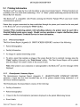
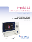
A "Welcome" screen is the first screen displayed after system start-up (Figure 2). From the Welcome
Screen the User may:
•
Begin a patient monitoring session
•
Take an Independent Blood Pressure measurement (optional feature, not available on all models).
•
Run the Demonstration Program
•
Access menus for various system configuration settings
•
Review patient records
When monitoring a patient, the BioZ.com® provides five (5) basic screens for presenting the various
hemodynamic parameters in a graphical, trending and/or data format. These screens are referred to as
the Monitoring Screen, Diagnostic Screen, Therapeutic Screen, Trend Screen, and Waveform Screen.
Each of these five screens is able to have its parameters and/or display configurations customized by
the User.
To ensure accuracy and stability in the display of the parameters provided by the BioZ.com®, the data
is averaged over a 30-heartbeat interval. The data is then updated (i.e., recalculated) and displayed
every 10 heartbeats. Therefore, the displayed values are based on data from the 10 most recent beats
plus the last 20 beats of the previous data update.
Note: The 30 beat Data Averaging frequency and 10 beat Display Update frequency are the default
settings. The User may set the Data Averaging and Display Update Frequency from between one and
60 beats to meet their specific needs (see section 8.1.1.3).
Prior to monitoring a patient, it is recommended that the User become familiar with the BioZ.com®
through the use of the tutorial presented in SECTION 6, BIOZ.COM® TUTORIAL, of this Manual.
The Demo Mode is a comprehensive feature that provides the User with a pre-programmed patient
case study. While in the Demo Mode, the User has access to all "Live Mode" features of the
BioZ.com® including, but not limited to, screen configurations, selection of parameters to be displayed,
and printing capabilities of data and/or reports. The Demo Mode provides the User with an excellent
educational method for the operation and many features/configurations of the BioZ.com®. After
completion of the Demo Mode Tutorial, the User should feel competent to begin a "live" monitoring
session on a patient.
BioZ.com® Operator's Manual
-7
CardioDynamics International Corporation
4.2
User Interface (Symbol Key)
The BioZ.com® consists of a 320 x 240 dot amber electroluminescent (EL) display screen with five
software-defined operating keys located below the screen. These five keys will be referred to as
"softkeys" throughout this document. In addition to the software-defined keys, there are hardware
defined keys, referred to as "hardkeys" throughout this document. Depending on the operational
status of the BioZ.com®, not all the softkeys and hardkeys will be active at any given time. Any
softkey or hardkey that is not active for a given screen, and pressed by the User, will evoke an audible
signal but will not affect the operation of the BioZ.com® in any way.
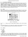
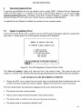
4.2.1 Softkeys
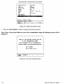
Softkeys are screen specific (i.e., they perform different functions depending on the current screen
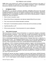
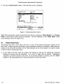
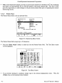
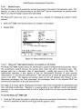
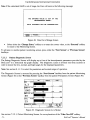
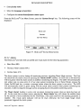
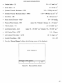
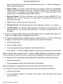
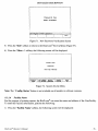
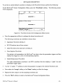
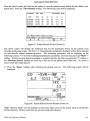
display). For example, text entries may be performed with the softkeys. When it is necessary to enter
text into a field (e.g., the Patient Name field, Facility Information), the following screen is displayed:
T&xt Entry Scr&&n
Text Entry: •
B C D E F
H I J K L
N 0 P
R
T U
Z
SPACE
v. w
. X,
Acc&pt
L&tt&r
Figure 1. Text Entry Screen
The '-1,
letter.
i,
~, -7' softkeys are used to navigate through the alphabet in order to select the desired
On the External Keyboard, keys <PI> through <P5> correspond to the five softkeys from left to right
(i.e., the <PI> keyboard key is equivalent to the left most softkey on the BioZ.com®).
4.2.2
Hardkeys
4.2.2.1 Menu
The 'Menu' hardkey is active from the Welcome Screen (Figure 2) and from the patient clinical
monitoring screens. Pressing the 'Menu' hardkey will take the User to a screen with five softkey
choices acting as a menu. These softkeys will give the User access to menus that will provide control
over system defaults/features and screen display configurations.
- 8-
BioZ.com@ Operator's Manual
GETTING STARTED
Keyboard equivalent: Simultaneously pressing the -cCtrb- and M keys.
4.2.2.2 Next Screen
The 'Next Screen' hardkey is active only while a patient clinical data monitoring screen is displayed.
Pressing the 'Next Screen' hardkey cycles the User through the five screens in the following order:
Monitoring Screen, Diagnostic Screen, Therapeutic Screen, Trend Screen, and Waveform Screen. The
order then repeats. The 'Next Screen' hardkey can also be used for scrolling through lists of patient
records and lists of data records within a patient file.
Keyboard equivalent: Simultaneously pressing the -cCtrb- and N keys.
4.2.2.3 Previous Screen
The 'Previous Screen' hardkey is active only when one of the five (5) patient monitoring screens are
being displayed. Pressing the 'Previous Screen' hardkey cycles the User through the five patient
clinical data monitoring screens in the opposite order of the 'Next Screen' hardkey. The 'Previous
Screen' hardkey can also be used for scrolling through lists of patient records and lists of data records
within a patient file.
Keyboard equivalent: Simultaneously pressing the -cCtrb- and P keys.
4.2.2.4 Event
The 'Event' hardkey is active while monitoring in both live and demo modes. Pressing the 'Event'
hardkey performs the function of attaching a User-defined text string to the patient record for use in
patient summary and trend reports (see Section 8.3). There is a green LED indicator next to the
'Event' hardkey that is energized while the BioZ.com® is storing the record.
Keyboard equivalent: Simultaneously pressing the -cCtrb- and E keys.
4.2.2.5 Digits (0-9)
The 0-9 digit hardkeys are used in various menus where numerical input is required from the User.
Keyboard equivalent: 0-9 keys.
BioZ.com@ Operator's Manual
- 9
CardioDynamics International Corporation
4.2.2.6 Clear
The 'Clear' hardkey is used in various menus in conjunction with the 0-9 digit hardkeys. When a field
is displayed that requires either an alphabetical or numerical entry from the digit softJhardkeys,
pressing the 'Clear' hardkey will let the User erase an entry and start over.
Keyboard equivalent: Simultaneously pressing the <Ctrl> and C keys.
4.2.2.7 Enter
The 'Enter' hardkey is used in various menus to accept a keyed-in or selected value.
Keyboard equivalent: Press the <Enter> key.
4.2.2.8 Stop Monitoring
Pressing the 'Stop Monitoring' hardkey will stop the monitoring session and take the User to the
BioZ.com® Welcome screen (Figure 2). The LED next to this hardkey is illuminated when no
monitoring is taking place. The LED will be off while monitoring either an actual patient or when
operating in demo mode.
Keyboard equivalent: Press the <Esc> key.
- 10-
BioZ.com@ Operator's Manual
GETTING STARTED
4.2.2.9 Print
The 'Print' hardkey is active at various times throughout the patient monitoring session, including all
patient clinical data monitoring screens and the Review Records screens. After pressing the 'Print'
hardkey, a menu appears giving printing options (see section 8.3). After printing (a green LED is on
when the BioZ.com® is communicating with a printer), the User returns to the screen of entry. A
message is displayed informing the User of a connection problem if the printer does not respond.
Keyboard equivalent: Simultaneously pressing the <Ctrl> and L keys.
4.2.2.10 Alarm ON/OFF
Pressing the 'Alarm ON/OFF' hardkey will enable and disable the BioZ.com® alarm system. An
LED next to the hardkey will indicate green when the alarm system is enabled. The LED will
automatically indicate red or amber (depending on the model) if the User disables the system, stops
patient monitoring, or enters a message screen where the alarm system is not active. The alarm system
will be enabled (and the LED indicate green) when monitoring is resumed.
Keyboard equivalent: Simultaneously pressing the <Ctrl> and B keys.
4.2.2.11Reset Alarm
The 'Reset Alarm' hardkey is active only on patient monitoring screens when an alarm condition has
been met. Pressing the 'Reset Alarm' hardkey will silence the audible alarm for the amount of time
established by the Time Delay default, if the alarm's audible feature is enabled (see section 8.1.1.1).
The 'Reset Alarm' function will not deactivate the visual alarm indicator; otherwise the User might
forget which parameter triggered the alarm system.
Keyboard equivalent: Simultaneously pressing the <Ctrl> and R keys.
BioZ.com® Operator's Manual
- 11
CardioDynamics International Corporation
4.2.2.12 Manual Deflate (if equipped with BioZ.com® Blood Pressure module)
The 'Manual Deflate' hardkey is used to manually trigger the BioZ.com® Cuff to deflate. This key
gives the User control over the cuff in case of system malfunction or patient discomfort. During an
error-free blood pressure measurement cycle, the cuff will deflate automatically.
Keyboard equivalent: Simultaneously pressing the <Ctrl> and D keys.
4.2.3 LED Indicators
In addition to the LED indicators associated with the hardkeys listed above, there are other LED
Indicators associated with the operating status of the BioZ.com®.
4.2.3.1 Power Source Status
• MainsAC:
There is a green LED labeled 'Mains AC' that is illuminated when the BioZ.com® is turned on and the
power source is from either 11OVAC or 220VAC.
•
Battery:
~---I
If the BioZ.com® is equipped with the optional battery power source, there is a green LED, which may
be labeled 'Battery' that is illuminated while power is being supplied by the battery.
•
Charge:
During charging of the battery (if equipped with the optional battery power source), an LED, which
may be labeled 'Charge' is illuminated.
- 12 -
BioZ.com® Operator's Manual
GETTING STARTED
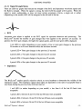
4.2.3.2 Signal Strength Status
There are LED bar graphs that indicate the strength of the ECG and Impedance waveform signals and
the Battery strength. When the signal is strong, the entire LED bar graph will be green. When the
signal is weak, undetectable, or does not meet certain acceptance criteria, a single red or amber
(depending on the model) LED will be energized at the left end of the bar .
•
ECG
Automatic gain adjust is applied to the ECG signal for optimum detection and processing. The
BioZ.com® records the number of gain changes that were applied in the previous 25 seconds. In
general, the fewer gain changes, the higher the signal quality, and the more green LEDs displayed.
I red LED (or amber depending on your model) = Four or more gain changes in the previous
25 seconds or no R wave detected within the last three seconds.
=Three gain changes in the previous 25 seconds
2 green LEDs =Two gain changes in the previous 25 seconds
3 green LEDs = One gain change in the previous 25 seconds
4 green LEDs =Zero gain changes in the previous 25 seconds
1 green LED
•
Impedance
The BioZ.com® applies specific rejection criteria to every heartbeat to determine the validity of the
impedance signal. The Impedance signal status lights are dependent on the ratio of acceptable beats to
total beats during the previous forty (40) beat interval.
1 red LED (or amber depending on your model)
acceptable
1 green LED
= less
than 6 of the last 40 beats were
=between 6 and 15 of the last 40 beats were acceptable
=between 16 and 25 of the last 40 beats were acceptable
3 green LEDs =between 26 and 35 of the last 40 beats were acceptable
2 green LEDs
BioZcom® Operator's Manual
- 13
CardioDynamics International Corporation
4 green LEDs
= between 36 and 40 of the last 40 beats were acceptable
• Battery
1 red LED (or amber depending on your model) = less than 20 percent of full capacity
1 green LED = between 20 and 39 percent of full capacity
4.2.4
2 green LEDs
=between 40 and 59 percent of full capacity
3 green LEDs
= between 60 and 79 percent of full capacity
4 green LEDs
=80 percent or greater of full capacity
External Connections
4.2.4.1 Front Panel
• NIBP Port (If equipped with the optional BioZ.com® blood pressure monitor)
• Patient Cable
This symbol indicates that the device has type BF defibrillation protection.
4.2.4.2 Rear Panel
• Warning Symbol
With respect to electric shock, fire and mechanical hazards only, in accordance with UL 2601-1
<48 SK>.
• Printer Port - Uni-directional communication with Hewlett Packard PCL3 (and more recent) print
language protocol printers.
•
Serial Output - Not used at this time.
- 14 -
BioZ.com® Operator's Manual
GETTING STARTED
•
Serial Input - Used when communicating with an external device, such as a Pc.
•
Keyboard - Allows a standard PC keyboard to be connected to facilitate data entry.
BioZ.com® Operator's Manual
- 15
QUICK-ST ART INSTRUCTIONS
5
QUICK-START INSTRUCTIONS
NOTE: Before using the BioZ.com® for monitoring a patient, read all the information in this manual.
1. Cleanse the sensor sites and apply the sensors.
2. Connect Patient cable to the BioZ.com® and to the patient sensors.
3. If automatic blood pressure detection is desired, connect the blood pressure cuff to the BioZ.com®
(if the model is equipped with this feature) and to the patient.
4. Connect the printer cable between the printer and the BioZ.com®. Connect the power cord to the
printer and tum on the printer.
5. Tum the 'Power' switch on the back panel to On. Ensure that the power cord is connected to
either a 11 OVAC or 220VAC power source.
6. Press the 'Start Monitor' softkey.
7. Enter the patient information; press 'Enter', or the 'J,' directional arrow softkey after each entry.
8. Select the method of Blood Pressure determination (i.e., 'BioZ.com® Cuff' or 'Manual Entry').
9. Press the 'Start Monitor' softkey after all entries are complete.
10. The BioZ.com® displays the Monitoring screen. If necessary, press the 'Change ECG Vector'
softkey to obtain optimal ECG signal.
/
11. After 30 acceptable heartbeats (depending on the Data Averaging frequency), the BioZ.com®
displays the first data set.
12. Press either the 'Next Screen' or 'Previous Screen' hardkeys to scroll through the various patient
clinical data monitoring screens.
13. When finished monitoring, press the 'Stop Monitoring' hardkey to end the session.
BioZ.com® Operator's Manual
- 17
BIOZ.COM® TUTORIAL
6
BIOZ.COM® TUTORIAL
The tutorial presented in this section should provide the User with a good working knowledge of the
BicZcom". It is recommended that the tutorial be completed in the order presented. For a detailed
description on an individual topic/feature, the User should refer to the respective section of this
manual.
The Demo Mode allows a User to become familiar with the BioZ.com® without actually having a
patient connected to the device. A pre-programmed waveform is stored in the device in order to
represent an actual patient. All normal BioZ.com® features are accessible while operating in the demo
mode. Any configuration changes made while operating in the demo mode will apply to all future
actual-patient monitoring sessions. The tutorial will demonstrate how to change various default
settings/configurations available on the BioZ.com®. By completing the tutorial, the User is afforded an
ideal opportunity to configure the BioZ.com® to their specific requirements. The only differences
between live mode and demo mode from a User's perspective are the following:
Each screen will have "Demo Mode" flashing in the lower right corner.
Note: If a patient is connected to the instrument while in "Demo Mode", the hemodynamic parameters
and waveforms on the screen and recorded to the patient's file are not those of the actual patient.
6.1
Startup
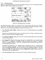
1) Connect the Printer to the Printer Port located on the rear panel and turn the printer on.
2) Connect the keyboard to the 'Keyboard' connector located on the rear panel.
Note: It is necessary to perform the above steps prior to performing step 3.
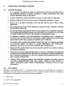
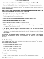
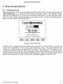
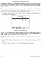
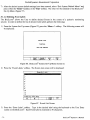
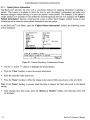
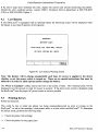
3) Connect the power cord to the rear panel of the BioZ.com® and plug into either a 110VAC or
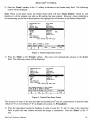
220VAC power source. Turn the Power Switch to the On position. The following screen will be
displayed after the boot-up sequence is complete.
CardioDynamics
CORPORATION
INTERNATIONAL
IB
II
E
IOZ_COM_
II T
II
Y
II
E
II
T
Hemodynamic Monitoring System
(800) 778-4825
(858) 535-0202
www.cardiodynanics.con
Software Version: 2.28
CDIC 2001, All Rights Reserved
START
MONITOR
I
TAKE
BP ONLY
I
REVIEW
RECORDS
I
SYSTEM
MENUS
I
SYSTEM
DEMO
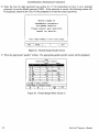
Figure 2. BicZcom" Welcome Screen
BioZ.com® Operator's Manual
- 19
CardioDynamics International Corporation
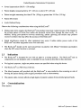
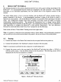
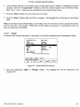
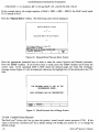
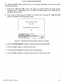
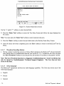
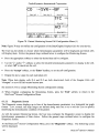
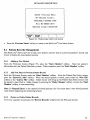
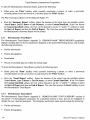
4) Press the 'System Demo' softkey. The following screen is displayed:
Date<MM/DD/VWV)
06/11/2000
Time:
13:28
P=tflent 1[1:
Patient Name:
Gender:
Required
Height:
Required
J.leight:
Required
BSA:
Required
Age:
BP:
Manual Entry
CUP <Default>:
6
PAOP <Default>:
10
Start Monitoring <NEJ.I FILE>
DEMO MODE
Exit
Figure 3. Patient Data Entry Screen
Note: When monitoring a patient for the first time, the User would press 'Start Monitor', not 'System
Demo', and the above screen would be displayed. The only difference is that 'Demo Mode' would
not be flashing in the lower right comer.
6.2
Patient Data Entry
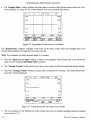
The Patient Data Entry screen allows the User to enter all the patient information required by the
BioZ.com® to detect, process, and display various parameters relating to the patient's cardiac function.
Except for the Patient ill and Name, all the fields displayed on the screen require User specific entries
in order to begin a monitoring session.
I) In the Patient ill field, enter the patient's ill number by pressmg the appropriate numerical
hardkey(s)or typing from the keyboard. Up to nine (9) digits may be entered. Alphabetical
characters can not be entered in this field. If an incorrect number is entered, press the 'Clear'
hardkey or the <Backspace> key if using a keyboard to re-enter the number.
- 20-
BioZ.com® Operator's Manual
BIOZ.COM® TUTORIAL
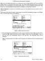
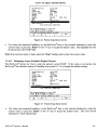
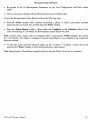
2) Press the 'Enter' hardkey or the '-I,' softkey to advance to the Gender entry field. The following
screen will be displayed:
Note: When in the demo mode, the Patient Name field will have 'Demo Patient' locked in, and
therefore it will be skipped over after an ill number has been entered. However, when conducting a
live monitoring session on an actual patient, the highlight bar will advance to the Patient Name field.
Date(MM/DD/YYYY)
Time:
Patient 10:
Patient Hame:
06/11/2000
13:3"
2233.... 556
Demo Patient
I;'endet":
RequIred
Height:
Required
I.leight:
Required
BSA:
Required
Age:
BP:
Manual Entry
CUP (Defaul t):
6
10
PAOP (Default):
Start Monitoring <HEI.l FILE>
DEMO MODE
Exit
Figure 4. Patient Data Entry Screen
3) Press the 'Male' or the 'Female' softkey. The cursor will automatically advance to the Height
field. The following screen will be displayed:
Date<MM/DD/YYYY)
Time:
Patient 10:
Patient Hame:
Gender:
06/11/2000
13:3..
2233.... 556
Oemo Patient
Female
I.leight:
Required
BSA:
Required
Age:
BP:
Manual Entry
CUP (Default):
6
10
PAOP (DefauIO:
Start Monitoring <HEI.l FILE>
DEMO MODE
Exit
Figure 5. Patient Data Entry Screen
The accuracy of some of the data provided by the BioZ.com® may be compromised on persons under
120cm (4' 0") or over 230cm (7' 6") in height (see section 2.2, Precautions).
4) Press the appropriate numerical hardkeys in order to enter the oft' and 'in' data in the respective
field, or press the 'cm' softkey and enter the height in centimeters. Press the 'Enter' or the '-I,'
key.
BioZ.com® Operator's Manual
- 21
CardioDynamics International Corporation
Note: If an entry greater than eleven (11) is entered into the 'in' field, the BioZ.com® will convert the
entered value to it's equivalent feet and inch value. For example, 0 ft 71 in may be entered in lieu of 5
ft 11 in. If the value entered is out of the required range (i.e., less than 4 ft 0 in or greater than 7 ft 6
in) the User will be prompted to either accept or proceed prior to beginning the session.
Note: If 'Proceed' is selected, the monitoring session can still proceed but data accuracy may be
compromised.
If the value for the patient's height is within range, the cursor will automatically advance to the Weight
field. The following screen will be displayed:
Date(MM/DD/YYYY)
Time:
Patient 10:
Patient Name:
Gender:
Height:
06/11/2000
13:3"
2233H556
Demo Patient
Female
5 ft 6 in
Age:
Required
BPI
Manual Entry
CUP (Default):
IS
PAOP (Default):
10
Start Monitoring (NEW FILE)
DEMO MODE
Exit
Figure 6. Patient Data Entry Screen
5) Press the appropriate numerical keys in order to enter the patient's correct weight (in units of lbs.),
or press the 'kg' softkey and enter the correct weight in units of kg. Press the 'Enter' or the '.l.'
key, the cursor will automatically advance to the Age field. The following screen will be
displayed:
Note: The Body Surface Area (BSA) will be calculated and displayed after the weight has been
entered.
Date(MM/DD/YYYY)
Time:
Patient 10:
Pat i ent Name:
Gender:
Height:
Weight:
06/11/2000
13:3"
2233H556
Demo Patient
Female
5 ft 6 in
119 Ibs
BSA: 1.60
BP:
Manual Ent r y
CUP (Default):
6
10
PAOP (Default):
Start Monitoring <NEW FILE)
Use keypad/keyboard to input Age.
or ENTER to accept.
Pr ess
+t
DEMO MODE
Exit
Figure 7. Patient Data Entry Screen
- 22 -
BioZ.com® Operator's Manual
BIOZ.COM® TUTORIAL
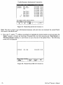
6) Press the appropriate numerical keys in order to enter the patient's age in years. Press the 'Enter'
or the 'J,' key, the cursor will automatically advance to the Blood Pressure field. The following
screen will be displayed:
Date(MM/DD/YYYY)
Timel
Patient ID:
Pat i ent Namel
Genden
Heightl
\.Jeightl
Agel
1313..
2233....556
Demo Patient
Female
5 ft 6 in
119 lbs
BSAI 1.60
2..
EP:
t1,nu,1 Erit ru
06/11/2000
CUP (Defaul t)1
6
PAOP (Default)1
10
Start Monitoring <NE\.J FILE>
DEMO MODE
Exit
Figure 8. Patient Data Entry Screen
The BioZ.com® allows the User to select one of two methods for obtaining the patient's blood
pressure: the BioZ.com® Cuff, or Manual Entry.
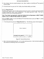
7) Press the 'Manual Entry' key. The following screen will be displayed:
Systolic/Diastolic Ualues
~--
/ --
Calculated Mean Arterial Pressure I
--Use keypad/keyboard to input BP.
Press ENTER to accept.
MAP value must be between 30-220 mmHg
SYSTOLIC IDIASTOLIC
I
I
..
DEMO MODE
BACK
I
Figure 9. Manual Blood Pressure Entry Screen
BioZ.com® Operator's Manual
- 23
CardioDynamics International Corporation
8) Press the appropriate numerical keys in order to enter the correct systolic and diastolic pressures.
Press 'Enter'. If the calculated MAP is NOT within the allowed range, the "Data Out of Range"
message screen (Figure 41) will be displayed; otherwise, the cursor will automatically advance to
the CVP field. The following screen will be displayed:
Note: For information on obtaining blood pressure via the BioZ.com® Cuff, refer to section 7.2.4.7.
Date(MM/DD/YYYY)
Time:
Patient 10:
Patient Name:
Gender:
Height:
lJeight:
Age:
BP:
Clip
1
Det aul t
"06/11 /2000
13:3i
2233H556
Demo Patient
Female
5 ft 6 in
119 lbs
2i
BSA: 1.60
Manual Entry
I':>
':
PAOP (Default):
10
Start Monitoring (NEIJ FILE>
DEMO MODE
Exit
Figure 10. Patient Data Entry Screen
The BioZ.com® allows the User to enter the patient's actual CVP and/or PAOP. Refer to section
8.1.1.3 for a detailed description. If these values are not known, the BioZ.com® default setting for
CVP and PAOP is 6 and 10 mmHg, respectively.
Note: CVP is used in the calculation of Systemic Vascular Resistance (SVR) and the Systemic
Vascular Resistance Index (SVRI). PAOP is used in the calculation of Left Cardiac Work (LCW) and
Left Cardiac Work Index (LCW!). Depending on the value for the Mean Arterial Pressure (MAP), for
every one mmHg error in the CVP and/or PAOP a one to one and half percent error in SVR and/or
LeW will be introduced.
For CVP / SVR:
SVR [dyne sec cm']
=(MAP -
CVP) x 80/ CO
If MAP = 90 mmHg, CVP = 6 mmHg, and CO = 5.5 Umin, then
SVR
= (90 -
6) x 80/5.5
= 1221 dyne sec cm's
If the actual CVP was 8 mmHg (a 2-mmHg underestimation on the part of the BioZ.com®), then
SVR = (90-8) x 80/5.5 = 1193 dyne sec em"
The percent error in the calculated SVR is:
Percent error = 100% x (SVR calc - SVR true) / SVR true = 100% x (1221 - 1193) /1193 = 2.34%
Therefore, in this example, a 2-mmHg underestimation of CVP would result in a 2.34% overestimation
of SVR.
- 24-
BioZ.com® Operator's Manual
BIOZ.COM®TUTORIAL
For PAOP / LCW:
LCW [kg m]
If MAP
= 0.0144 x (MAP -
PAOP) x CO
= 90 mmHg, PAOP = 10 mmHg, and CO = 5.5 Umin, then
LCW
=0.0144 x (90 -
10) x 5.5 =6.3 kg m
If the actual PAOP is 15 mmHg (a 5mmHg underestimation on the part of the BioZ.com®), then
LCW
=0.0144 x (90-15) x 5.5 =5.94 kg m
The percent error in the calculated LCW is:
Percent Error = 100% x (6.3-5.94) / 5.94 = 6.7%
Therefore, in this example, a 5 mmHg underestimation of PAOP will result in a 6.7% overestimation
of the LCW.
Press the 'Enter' or the '.1' key twice in order to accept the default values. The cursor will
automatically advance to the Start Monitoring field. The following screen will be displayed:
Date(MM/DD/YYYY)
06/11/2000
13:3i
Time:
Patient ID:
2233H556
Patient Name:
Demo Patient
Gender:
F"emale
Height:
5 ft 6 in
I.leight:
119 lbs
BSA: 1.60
Age:
2i
BP:
Manual Entry
CVP <Default):
6
PAOP (Defaul1):
10
St sr t 110m t orrriq ,tJElJ FILE;
DEMO MODE
Exit
Figure 11. Patient Data Entry Screen
Press the 'Start Monitor' softkey to begin monitoring.
6.3
Patient Monitoring (Demo Mode)
When monitoring a patient, the BioZ.com® provides five (5) basic screens for presenting the various
hemodynamic parameters;
•
Monitoring Screen
•
Diagnostic Screen
•
Therapeutic Screen
BioZ.com® Operator's Manual
- 25
CardioDynamics International Corporation
• Trend Screen
• Waveform Screen
Each of these five screens is able to have its parameters and/or display configurations customized by
the User. The tutorial will demonstrate how to accomplish these changes.
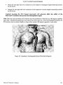
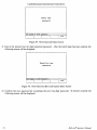
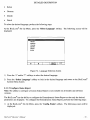
I) Press the 'Start Monitor' softkey to begin the monitoring session. The following screen will be
displayed:
Note: If either the height, weight, or age were out of the recommended range, or omitted, an error
message will be displayed prompting the User to enter or re-enter the correct values or Proceed with
the monitoring session with the out of range values. If the User chooses to proceed, the calculated SV,
Sl, CO, Cl, SVR, SVR1, LCW, and LCWl may not be an accurate indication of the patient's actual
values.
mmHg
ECG Vector 2
1792
TFC
'----......-'''''--'1.. 1
Impedance 30 Beat Average
/kohm
33
ACI
/100
se~
89
DEMO MODE
TAKE NEI.l
BP
Figure 12. Monitoring Screen (Demo Mode)
Note: Your screen configuration may vary depending on previous configuration settings. The actual
values will not appear until the appropriate number of heartbeats have been processed and accepted.
The Monitoring Screen consists of a maximum of five (5) data display cells and two (2) graphic
display cells. The BioZ.com® provides the User with the ability to set the number of active graphic
and data cells as well as the parameters displayed by those cells.
- 26-
BioZ.com® Operator's Manual
BIOZ.COM®TUTORIAL
The 'Menu' hardkey provides the User with access to the necessary screens for making custom
changes to the Bioz.com'". To configure the Monitoring Screen:
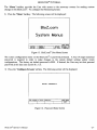
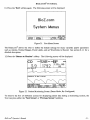
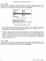
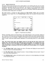
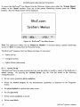
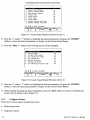
2) Press the 'Menu' hardkey. The following screen will be displayed:
BioZ.com
System Menus
SYSTEM
SET-UP
I SCREENS
CONFIG.
I
DEMO MODE
I UPDATE IRETURN TO
PT. INFO.
MONITOR
Figure 13. BioZ.com® User Menu Screen
The screen configuration menu on the BioZ.com® is password protected. A four (4) digit numerical
password is required in order to make changes to the system default settings and/or screen
configurations. The factory set default password is 1111. If desired, the User may set their personal
password at this time (see section 8.1.1.5).
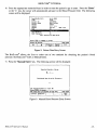
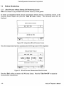
3) Press the 'Configure Screens' softkey. The following screen will be displayed:
Enter Password
Use keypad to enter password.
I
I
I
DEMO MODE
EXIT
I
Figure 14. Password Entry Screen
BioZ.com® Operator's Manual
- 27
CardioDynamics International Corporation
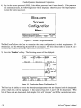
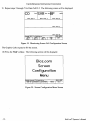
4) Key in the correct password (1111, if the default password hasn't been altered). If the password
was entered correctly, the following screen will be displayed; otherwise, you will be prompted to
re-enter the correct password.
Bioz.com
Screen
Configuration
Menu
Choose Screen To Confiaure.
MONITOR !DIAGNOSTIC ~AUEFORM
I
I
TREND
DEMO MODE
EXIT
I
Figure 15. Screen Configuration Menu
The BioZ.com® allows the User to customize the screen configuration(s) to their requirements. For
this tutorial, only the Monitoring Screen will be customized. The User should refer to section 8.1.2 to
customize the configuration of the other patient monitoring screens.
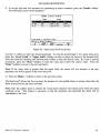
5) Press the 'Monitor' softkey. The following screen will be displayed:
CO
l/min
Data Cell 1
SVR dyn
sec
BP
mmHg
Data Cell 3
Data Cell 2
TFC
A: ohm
Data Cell ..
ACI /100
Choose Cell To Confiaure.
DATA
DATA
DATA
CELL 2
CELL 3
CELL 1
I
I
I
se2
Data Cell 5
DEMO MODE
EXIT
MORE
..
I
Figure 16. Monitoring Screen Configuration (1)
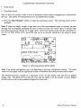
The User has the ability to choose the hemodynamic parameters that are displayed and the data/graphic
cell in which they will be displayed. In this tutorial, Data Cells 4 and 5 will be deactivated. When
both of these cells are deactivated, both Graphic Cells will "elongate" and fill the vacated screen area.
- 28 -
BioZ.com® Operator's Manual
BIOZ.COM® TUTORIAL
6) Press the
'More~'
softkey. The following screen will be displayed:
CO
l/min
SVR
Data Cell 1
dyn sec
BP
mmHg
Data Cell 3
Data Cell 2
TFC
/kohm
Data Cell i
ACI
Choose Cell To Confiaure.
DATA
DATA
CELL i
CELL 5
I
I
I
2
/100 sec
Data Cell 5
DEMO MODE
BACK
EXIT
..
I
Figure 17. Monitoring Screen Configuration (2)
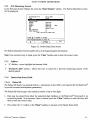
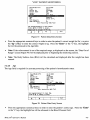
7) Press the 'Data Cell 4' softkey. The following screen will be displayed:
'.i,M_••
•
intl'• • •'
2. Ueloci ty Index
3. Acceleration Index
i. Left Cardiac I-lork
0-5
5. Left Car di ac I-lor k Index
6. Pre-Ejection Period
7. Left Uentricular Ej ection Time
8. Systolic Time Ratio
9. Respiration Rate
10. OFF
Not Available
to select parameter.
Use
Press ACCEPT or ENTER to set Cell D-X.
ACCEPT
MORE
"'1'
...
I
l'
I
I
.
DEMO MODE
EXIT
I
Figure 18. Hemodynamic Parameter Menu (1)
The Parameter that is currently displayed in Data Cell 4 will be highlighted and D-4 will be displayed
to the right of the parameter. To deactivate D-4:
8) Press the 'J..' softkey to select 'off'. Press either the 'Accept' softkey or the 'Enter' hardkey.
Press the 'Exit' softkey, the user will be returned to the Monitoring Screen Configuration Screen
(Figure 17).
BioZ.com® Operator's Manual
- 29
CardioDynamics International Corporation
9) Repeat steps 5 through 7 for Data Cell 0-5. The following screen will be displayed:
CO
l/min
Data Cell 1
SVR
dyn sec
BP
mmHg
Data Cell 3
Data Cell 2
Data Cell i
Choose Cell To Confioure.
DATA
DATA
DATA
CELL 1
CELL 2
CELL 3
I
I
I
Data Cell 5
DEMO MODE
MORE
EXIT
..
I
Figure 19. Monitoring Screen Cell Configuration Screen
The Graphic Cells expand to fill the screen.
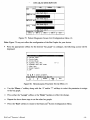
10) Press the 'Exit' softkey. The following screen will be displayed:
Bioz.com
Screen
Configuration
Menu
Choose S~reen To Confioure.
MONITOR IDIAGNOSTIC I ~AUErORM
I
TREND
DEMO MODE
EXIT
I
Figure 20. Screen Configuration Menu Screen
- 30-
Bioz'com@ Operator's Manual
BIOZ.COM® TUTORIAL
11) Press the 'Exit' softkey again. The following screen will be displayed:
BioZ.com
System Menus
SYSTEM
SET-UP
I SCREENS
CONnG.
I
DEMO MODE
I UPDATE IRETURN TO
PT. INro.
MONITOR
Figure 21. User Menu Screen
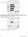
The BioZ.com® allows the User to define the default settings for many variables and/or parameters
such as Alarms, Normal Ranges, Event Labels, and set Waveforms to Record. See section 8.1.1 for a
detailed description.
12) Press the 'Return to Monitor' softkey. The following screen will be displayed:
CO
3.9
l/minSVR dyn secBP
1792
1209'3
mmHg
80
ECG Vector 2
Impedance 30 Beat Average
Figure 22. Patient Monitoring Screen (Demo Mode, Re-Configured)
To observe the five (5) different screens for displaying patient data during a monitoring session, the
User can press either the 'Next Screen' or 'Previous Screen' hardkeys.
BioZ.com® Operator's Manual
- 31
CardioDynamics International Corporation
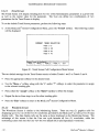
13) Press the 'Next Screen' hardkey. The following screen will be displayed:
HIGH
co
6.3
1096
89
TFC
33.3
8.7
H.2
13°78
20H
usa
230
70.0
DEMO MODE
TAKE NEI.l
BP
Figure 23. Diagnostic Screen (Demo Mode)
The Diagnostic screen will display up to four (4) of the available parameters at a time. The User may
customize the Diagnostic Screen to display the parameters of their choice (see section 8.1.2). For an
explanation of the Diagnostic Screen, see section 7.2.5.2.
14) Press the 'Next Screen' hardkey. The following screen will be displayed:
51
DEMO MODE
TAKE NEI.l
BP
Figure 24. Therapeutic Screen (Demo Mode)
For an explanation of the Therapeutic Screen, see section 7.2.5.3.
- 32-
BioZ.com@ Operator's Manual
BIOZ.COM® TUTORIAL
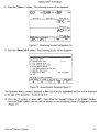
15) Press the 'Next Screen' hardkey. The following screen will be displayed:
co -
3.9
I 13:3i I SVR ........
1792
ro:o'" ......._....................
1696
8.5
1378
, 5
7i2
2.5
i2i
13:19
13:26
13:3i
TREND SCREEN
CHANGE
30 MINUTE lONE HOUR
TRENDS
SCALE
SCALE
I
13:i1
I
EXPAND
DATA
13:i9
DEMO MODE
FULL DATA
SCALE
I
Figure 25. Trend Screen (Demo Mode)
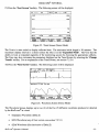
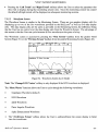
The X-axis is auto scaled to display collected data. The minimum initial length is 30 minutes. The
maximum display interval is 12 hours unless the User is in the 'Expanded Mode'. The User has the
ability to look at expanded segments of the monitoring session by choosing the appropriate softkeys.
The User may also customize the parameters displayed on the Trend Screen by selecting the 'Change
Trends'softkey. For an explanation of the Trend Screen, see section 7.2.5.4.
16) Press the 'Next Screen' hardkey. The following screen will be displayed:
CO 3.9
ECG Vector 2
Impedance 30 Beat Average
Figure 26. Waveform Screen (Demo Mode)
The Waveform Screen displays up to two (2) of the five (5) different waveforms produced or detected
by the BioZ.com® at a time:
•
Impedance Waveform (Delta Z)
•
ECG Waveform (any of four vectors, see section 7.2.5.1)
•
dZJdt Waveform (first derivative of Delta Z)
BioZ.com® Operator's Manual
- 33
CardioDynamics International Corporation
• Pacer Impulse Waveform (impulse for each pacemaker trigger)
• Spike Enhancement Waveform (ECa and Pacemaker impulse)
The default waveforms for the Waveform Screen are the Eca and Delta Z waveforms. The 'More
Waves' softkey provides the User with the ability to view the alternate waveforms. See sections
7.2.5.5 and 8.1.2.4.
17) Press the 'Next Screen' hardkey. The Monitoring Screen will be displayed (Figure 12).
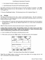
6.4
Printing
The BioZ.com® provides the User with a variety of pre-formatted reports. The print command is
active during all live monitoring sessions from the various patient monitoring screens as well as from
the Review Record screens. To Print:
1) With the BioZ.com® turned off, connect the printer cable from the printer port on the rear panel of
the BioZ.com® to a printer that uses Hewlett Packard PCL3 (or a more recent) communication
language protocol.
Note: The Printer should be connected and turned on prior to turning on the BioZ.com®
Caution! When monitoring patients with indwelling catheters, the printer must be used with a
HospitaIlMedical grade power supply. Should you have questions or require clarification, please
contact CardioDynamics Technical Service for more information.
2) Tum on the BioZ.com® and initiate a monitoring session as usual.
3) When ready to print, press the 'Print' hardkey. The following screen will be displayed:
CO
3.9
ECG Vector 2
l/minSVR dyn secBP
1792
mmHg
120/80
93
PRINT
SCREEN
Figure 27. Print Option Screen (Demo Mode, Re-Configured)
Note: When the 'Print' hardkey is pressed, the current screen display will not change; only the "soft
keys" at the bottom of the screen will change.
- 34-
Bio2.com® Operator's Manual
BIOZ.COM® TUTORIAL
The User may print any of the available pre-formatted reports.
description on the types of reports available.
See section 8.2 for a detailed
4) Press the appropriate softkey to print the desired report. The green Print LED will remain
illuminated until the report has been transmitted to the printer.
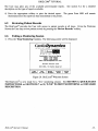
6.5
Reviewing Patient Records
The BioZ.com® provides the User with access to patient records at all times. From the Welcome
Screen the User may review patient records by pressing the 'Review Records' softkey.
6.6
Exiting a Monitoring Session
1) Press the 'Stop Monitoring' hardkey. The following screen will be displayed:
CardioDynamics
INTERNATIONAL
CORPORATION
IBIOZ.COM_
B
EAT
B
Y
B
EAT
Hemodynamic Moni1oring System
(800) 778-4825
(858) 535-0202
www.cardiodyna"ics.co"
Sof1uare Version: 2.28
CDIC 2001, All Righ1S Reserved
START
MONITOR
I
TAKE
BP ONLY
I
REVIE~
RECORDS
I
SYSTEM
MENUS
DEMO
I SYSTEM
Figure 28. BioZ.com®Welcome Screen
The BioZ.com® is now ready for a "live' monitoring session. See SECTION 5, QUICK-START
INSTRUCTIONS and SECTIONS 7 and 8, "LIVE" PATIENT MONITORING and DETAILED
DESCRIPTION.
BioZ.com® Operator's Manual
- 35
"LIVE" PATIENT MONITORING
7
"LIVE" PATIENT MONITORING
A patient monitoring session is initiated from the Welcome Screen (Figure 28). The 'Start Monitor'
function is used to begin a "live" monitoring session.
The following sections will explain the steps necessary to monitor a patient.
7.1
Patient Preparation
The first step in beginning a monitoring session is to attach the patient ICG sensors.
7.1.1 lCG Sensors
To obtain accurate results with the BioZ.com®, high quality, ICG sensors with low skin-to-electrode
impedance, proper spacing between transmitting and receiving sensors, and good adhesive properties
are required. The ICG sensors distributed by CardioDynamics meet these requirements.
Only use sensors that have been recently removed from the sealed package. Sensors are single use
disposable items. Check the package expiration date before use.
Note: The algorithm used to determine the stroke volume by Impedance Cardiography is
dependent on the ICG Sensor conductive gel/electrode type, spatial relationship, and site
placement. Use of non-CardioDynamics' approved ICG sensors will affect the ability of the
BioZ.com® to determine the patient's hemodynamic parameters.
7.1.2 Skin Preparation
7.1.2.1 Wet Gel Sensors (BZ-200, 201)
1) Shave the hair over the sensor sites if necessary.
2) Thoroughly clean the skin areas with alcohol or electrode prep pad. Make sure that the skin is
thoroughly dry before attaching sensors.
7.1.2.2 BioZtecC Sensors (BZ-4550-01)
1) Shave the hair over the sensor sites if necessary.
2) 'Dry prep' the sensor sites by mildly abrading the skin with the perforation on the sensor backing.
7.1.3 ICG Sensor Application
7.1.3.1 Wet Gel Sensors (BZ-200, 201)
1) Check the expiration date on the sealed pouch prior to opening. Open the sealed pouch and remove
the sensors. Verify that the gel is still moist!
2) Attach the reusable patient cable lead wires to the ICG sensors before removing the protective
backing from the sensors. The black and white snap leads should be snapped onto one dual ICG
BioZ.com® Operator's Manual
- 37
CardioDynamics International Corporation
sensor, and the red and green snap leads should be snapped onto another dual ICG sensor. This
should be repeated for both the left and right sets of patient cable lead-wires.
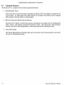
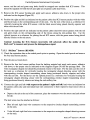
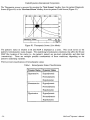
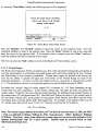
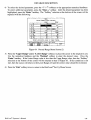
3) Remove the ICG sensor backing and apply each sensor, adhesive side down, to the proper sites
indicated on the diagram (Figure 29).
4) Position the right and left (as indicated on the patient cable) dual ICG sensor patches with the white
and black leads on the corresponding side of the neck. Use the root of the neck as a reference for
vertically locating the white ICG sensor, with the black sensor being placed directly superior and
inline with the ear lobe.
5) Position the right and left (as indicated on the patient cable) dual ICG sensor patches with the red
and green leads on the corresponding side of the thorax along the mid-axillary line. Use the
xiphoid process as a reference for placing the red ICG sensor, with the green sensor being placed
directly inferior to the red sensor.
Caution! Locating the ICG Sensors incorrectly will adversely affect the ability of the
BioZ.com® to measure and process the bioimpedance signal.
7.1.3.2 BioZtect™ Sensors (BZ-4550)
I) Check the expiration date on the sealed pouch prior to opening. Open the sealed pouch and remove
the four dual sensor patches.
2) Prep the skin as listed above.
3) Remove the four dual sensor patches from the backing material and apply each sensor, adhesive
side down, to the proper sites as indicated on the diagram (Figure 29) and the package label. The
wide rectangular shaped end should be positioned closest to the heart. For the neck use the root of
the neck as a reference for vertically locating the rectangular shaped detecting sensor with the
corresponding circular shaped transmitting sensor being positioned directly superior and inline
with the ear lobe. For the thorax use the xiphoid process as a reference for vertically locating the
rectangular shaped detecting sensor with the corresponding circular shaped transmitting sensor
being positioned directly inferior and along the mid-axillary line.
4) Connect the right and left (with respect to the patient's right and left) lead wires (as indicated on
the patient cable yoke and individual lead wire connectors) to their respective dual sensor sites as
follows:
• Depress the tab at the end of the connector, place the connector over the sensor stud and release
the tab.
The lead wires must be attached as follows:
• Blue left and right lead wire connectors to the respective circular shaped transmitting sensors
on the neck.
• Violet left and right lead wire connectors to the respective rectangular shaped detecting sensors
on the neck.
- 38 -
BioZ.com® Operator's Manual
"LNE" PATIENT MONITORING
•
Green left and right lead wire connectors to the respective rectangular shaped detecting sensors
on the thorax.
•
Orange left and right lead wire connectors to the respective circular shaped transmitting sensors
on the thorax.
Caution! Locating the ICG Sensors incorrectly will adversely affect the ability of the
BioZ.com® to measure and process the bioimpedance signal.
Note: Both the neck and thorax ICG sensors must be positioned so that they are 180 degrees opposite
each other. Should the patient have an invasive line, chest tube, etc. at the recommended locations, the
ICG sensors may be rotated slightly as long as they remain 180 degrees opposite of each other.
Figure 29. Impedance Cardiography Sensor Placement Diagram
BioZ.com® Operator's Manual
- 39
CardioDynamics International Corporation
7.2
Patient Monitoring
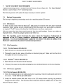
7.2.1 Blood Pressure without Starting leG Monitoring Session
Note: This feature is only available with software version 2.28 and greater.
To obtain an independent blood pressure measurement without starting a monitoring session, at the
Welcome Screen (Figure 28), press the 'Take BP Only' softkey. The following screen will be
displayed:
BioZ.com Blood Pressure
SBP / DBP (MAP)
~AITING
TAKE NE~
BP
I
HR
fOR DATA
16:05
I
I
EXIT
I
Figure 30. Independent Blood Pressure Screen
Once the measurement has been calculated, the following screen will be displayed:
BioZ.com Blood Pressure
SBP / DBP (MAP)
HR
120/80 (93)
60
mmHg
bpm
Measurement Taken At: li:26
TAKE NE~
BP
I
li:26
I
I
I
EXIT
Figure 31. Blood Pressure Measurement Results Screen
Press the 'Exit' softkey to return to the Welcome Screen. Press the 'Take New BP' to repeat the
blood pressure measurement.
- 40-
BioZ.com® Operator's Manual
"LIVE" PATIENT MONITORING
7.2.2 leG Monitoring Session
At the Welcome Screen (Figure 28), press the 'Start Monitor' softkey. The Patient Data Entry screen
will be displayed.
Oat e( MM/OO/YVYY)
Time:
06/12/2000
06:28
Pati ent Name:
Gender:
Required
Height:
Required
Weight:
BSA:
Required
Required
Age:
Manual Entry
BP:
CUP <Default):
6
PAOP (Defaul t):
10
Start Monitoring <NEW rILE>
Exit
Figure 32. Patient Data Entry Screen
The Patient Data Entry Screen enables entry of all required patient information.
Note: If an incorrect entry is made, press the 'Clear' hardkey and re-enter the correct value.
7.2.3
Softkeys
• '-1-' Softkey - move highlight bar between fields.
• 'Stored Pt. Info' softkey - allows the User to search for a previous monitoring session of the
desired patient.
7.2.4
Patient Data Entry Fields
7.2.4.1 Patient lD
The Patient ill field is an optional field (i.e., information in this field is not required for the BioZ.com®
to provide accurate hemodynamic parameters).
The Patient ill field accepts only numerical entries of up to nine digits.
• Data may be entered from either the numerical digit hardkeys on the BioZ.com® front panel or an
external keyboard. If an incorrect value is entered, press the 'Clear' hardkey to erase the entry and
then re-enter the correct value.
• Press either the
'-1-' softkey or the 'Enter' hardkey to advance to the Patient Name field.
BioZ.com® Operator's Manual
- 41
CardioDynamics International Corporation
• Note: If the Patient ill matches one that was previously entered into the Bio'Zcom'", the remaining
data fields will automatically fill in with that patient's previously entered data. The User is then
given the opportunity to make changes to the previously entered data prior to beginning the current
monitoring session.
7.2.4.2 Patient Name
The Patient Name field is also an optional field.
Oate(MM/OO/YYYY)
Time:
Patient 10:
06/12/2000
06:32
112233555
P ~t 1 errt tJ"'[He:
Gender:
Required
Height:
Required
Weightl
Requi r ed
BSA:
Age:
Required
BP:
Manual Entry
CUP (Oefaul t):
6
PAOP (Oefaul t):
10
Start Monitoring <NEW FILE>
Figure 33. Patient Data Entry Screen
The Patient Name field accepts up to 25 characters.
• Press the 'Enter Name' softkey to enter text into the Patient Name field. The Text Entry screen
will be displayed:
Text Entry Screen
Text Entry: •
c DE F
J K L
H
8
R
o P
u v w X,
z .
N
T
SPACE
Press <Accept Letter> after choosing each letter.
Press <ENTER> uhen done.
Accept
Letter
Figure 34. Text Entry Screen
•
If an. external keyboard is attached, simply type in the desired alphanumeric entry.
Press the
<Enter> key on the keyboard when finished.
- 42-
BioZ.com® Operator's Manual
"LIVE" PATIENT MONITORING
• If an external keyboard is not attached, press the appropriate arrow softkeys to highlight the desired
character, press the 'Accept Letter' softkey to enter the selected character into the Patient Name
field. The f--, and --7 entries are for moving the cursor within the text string.
• Press the 'Clear' hardkey if an incorrect entry was made.
• Press the 'Enter' hardkey after the field is complete. The highlight bar will advance to the Gender
field.
Note: If the Patient ill and Name fields are left blank, the User will only be able to identify the file by
the date and time of the session. While both of these fields are optional, it is beneficial to place an
entry in at least one of the fields.
7.2.4.3
Gender
The BioZ.com® requires the gender of the patient to accurately determine their hemodynamic status.
Oate( MM/DD/NVV)
Time:
Patient 10:
Patient Name:
00/12/2000
00:32
112233555
6endet-:
Pequl t" ed
DOE, JOHN
Height:
Required
BSA:
I.leight:
Required
Age:
Required
BP:
Manual Entry
CUP (Default):
0
PAOP (Default):
10
Start Monitoring (NEI.l fILE>
Exit
Figure 35. Patient Data Entry Screen
• Press the appropriate 'Male' or 'Female' softkey.
Height field.
BioZ.com® Operator's Manual
The highlight bar will be advanced to the
- 43
CardioDynamics International Corporation
7.2.4.4 Height
The Height field is required for accurate processing of the patient's hemodynamic status. The
accuracy of some of the data provided by the BioZ.com® may be compromised on persons under
120cm (48in) or over 230cm (90in) in height (see section 2.2, Precautions).
Oate<MM/DD/YYYY)
Time:
Patient 10:
Patient Name:
Gender:
00/12/2000
00:32
112233555
DOE, JOHN
Male
~eight:
Required
BSA:
Age:
Required
BP:
Manual Entry
CUP <Default):
0
PAOP <Default):
10
Start Monitoring <NE~ FILE>
Exit
Figure 36. Patient Data Entry Screen
• Press the appropriate numerical hardkeys in order to enter the oft' and 'in' data in the respective
fields, or press the 'cm' softkey to enter the height in centimeters. Press the 'Enter' or the '-I,' key.
The highlight bar will be advanced to the Weight field
• Note: If an entry greater than eleven (11) is entered into the 'in' field, press 'Clear' and re-enter
the correct value; otherwise the BioZ.com® will convert the entry to it's equivalent height in feet
and inches. For example, if 5 feet 13 inches is entered into the oft' and 'in' fields respectively, the
BioZ.com® will convert the entry to 6 feet 1 inch. Also, if the value entered is out of the required
range, as displayed on the screen, an error screen will be displayed prior to beginning the
monitoring session (Figure 45).
7.2.4.5 Weight
The Weight field is required for accurate processing of the patient's hemodynamic status. The
accuracy of some of the data provided by the BioZ.com® may be compromised on persons under 30 kg
(67 lbs) or over 155 kg (341 lbs) in weight (see section 2.2, Precautions).
- 44-
BioZ.com® Operator's Manual
"LIVE" PATIENT MONITORING
Oat e(MM/OO/YYVY)
Tillie,
Patient 10:
Pat ient Nallle:
Gender:
Height:
06/12/2000
06:32
112233555
DOE, JOHN
Male
6 ft 0 in
Age:
Required
BP:
Manual Entry
CUP (OefaulO:
6
PAOP (OefaulO,
10
Start Monitoring <NE~ rILE>
Use keypad/keyboard to input ~eight.
Press ....
or ENTER to accept.
l'
Range lIlust be between 67-3il lbs.
kg
....
Exi t
Figure 37. Patient Data Entry Screen
• Press the appropriate numerical keys in order to enter the patient's correct weight (in lbs.), or press
the 'kg' softkey to enter the correct weight in kg. Press the 'Enter' or the '-1-' key, the highlight
bar will be advanced to the Age field.
• Note: If the value entered is out of the required range, as displayed on the screen, the "Data Out of
Range" screen (Figure 45) will be displayed prior to beginning the monitoring session.
• Note: The Body Surface Area (BSA) will be calculated and displayed after the weight has been
entered.
7.2.4.6 Age
The Age field is required for accurate processing of the patient's hemodynamic status.
Oat e( MM/OO/YYYY)
06/12/2000
06:32
Tillle:
Patient 10:
112233555
Pat i ent Nallle:
DOE, JOHN
Gender:
Male
Height:
6 ft 0 in
185 lbs
BSA, 2.06
Weight:
Hqe:
Pequl'- ed
BP:
Manual Entry
CUP (OefaulO:
6
PAOP (Default):
10
Start Monitoring <NE~ rILE>
Use keypad/keyboard to input Age.
Press ....
or ENTER to accept.
l'
Exit
Figure 38. Patient Data Entry Screen
•
Press the appropriate numerical keys in order to enter the patient's correct age. Press the 'Enter'
or the '-1-' key, the highlight bar will be advanced to the Blood Pressure field.
BioZ.com® Operator's Manual
- 45
CardioDynamics International Corporation
7.2.4.7 Blood Pressure
The Blood Pressure field is required for accurate processin~ of the patient's hemodynamic status. The
accuracy of some of the data provided by the BioZ.com may be compromised on persons whose
MAP is less than 30 mmHg or greater than 220 mmHg.
The BioZ.com® allows the User to select one of two methods for obtaining the patient's blood
pressure:
• BioZ.com® NIBP cuff (optional feature, not available on all models)
• Manual Entry
Date<MM/DD/YYYY)
Time:
Patient 10:
Patient Name:
Gender:
Height:
06/12/2000
06:32
112233555
~eight:
185 lbs
Age:
'10
5P:
M~nu~l
DOE, JOHN
Male
6 ft 0 in
CUP <DefauIO:
6
PAOP <DefauIO:
10
Start Monitoring
8SA: 2.06
Entru
<NE~
FILE)
Exit
Figure 39. Patient Data Entry Screen
7.2.4.8 BioZ.com® Cuff(optionalfeature, not available on all models)
The BioZ.com® NIBP module utilizes the Oscillometric method in determining blood pressure values.
The oscillometric method measures the pressure pulse within the cuff in incremental steps. This
pressure pulse has a maximum value of approximately 1 mmHg that occurs at the MAP. A
sophisticated algorithm is then applied to plot the Oscillometric Envelope of pulse pressure
measurements vs. cuff pressure measurements. The cuff pressure at which the peak: pressure pulse
occurs is the MAP. The diastolic and systolic values are the cuff pressures that intersect at pre
determined percentages (not fixed percentages, but percentages based on the measured MAP and
pressure pulse amplitude) of the peak: pulse pressure.
The shape of an actual patient Oscillometric Envelope varies from measurement-to-measurement and
from individual-to-individual. Therefore it is quite possible to have different systolic and diastolic
pressures for the same measured MAP as well as different MAPs for the same systolic and diastolic
pressures.
To use the BioZ.com® NIBP cuff:
• Wrap the Cuff around the patient's upper arm (observe the precautions listed below). Ensure that
the cuff is positioned so that the arrow aligns with the patient's artery.
- 46-
BioZ.com® Operator's Manual
"LIVE" PATIENT MONITORING
• Connect the coiled inflation tube to the NffiP Port on the front panel of the BioZ.com®.
• Press the 'BioZ.com Cuff' softkey if that is the desired method of blood pressure determination.
Once the monitoring session begins, the BioZ.com® will automatically operate the blood pressure cuff
to obtain the measurement.
Note: In order to obtain an accurate blood pressure measurement and to ensure the safety of the
patient, it is essential that the following precautions be observed:
• Use only the blood pressure cuff provided with the device.
• Use the proper size cuff for the patient's arm.
• Ensure that the cuff is evenly and snugly wrapped around the patient's arm.
• Ensure that the bladder within the cuff is not folded.
• Ensure that all connections are tight so as to prevent leakage.
• While making blood pressure measurements be sure to avoid any compression or restriction
of the pressure tube leading to the cuff.
• The operator is advised to observe directly that inflation of the cuff does not result in
prolonged impairment to the patient's circulation.
• The patient's arm should remain relaxed and still while the blood pressure cuff is inflating
and deflating.
The BioZ.com® will update the patient's blood pressure every five (5) minutes. The five-minute
interval may be customized to meet the User's requirements. See section 8.1.1.3 for a detailed
description.
7.2.4.9 Manual Entry
When 'Manual Entry' is the source for entering the SBP and DBP the BioZ.com® will calculate a
MAP using the following algorithm:
If [(SBP-DBP)IDBP] < 0.5 Then KP
=0.333
If [(SBP-DBP)IDBP] > 1.0 Then KP
=0.25
KP =0.333 -{ [(SBP -DBP)IDBP) - 0.5]/6}
MAP
=DBP + [KP (SBP-DBP)]
For example:
If a BP
= 150/65 is entered manually into the BioZ.com® the calculated MAP would be:
BioZ.com® Operator's Manual
- 47
CardioDynamics International Corporation
(150-65)/65 = 1.31, therefore, KP = 0.25 and MAP = 65 + [0.25( 150-65)] = 86.25
In the example above, the simple equation of MAP
93.33 instead of 86.25
= DBP + (SBP -
DBP)/3, the MAP would equal
Press the 'Manual Entry' softkey. The following screen will be displayed:
Systolic/Diastolic Values
--- / --
Calculated Mean Arterial Pressure :
--Use keypad/keyboard to input BP.
Press ENTER to accept.
MAP value must be betueen 30-220 mmHg
SYSTOLIC IDIASTOLIC
I
I
I
.
BACK
Figure 40. Manual Blood Pressure Entry Screen
Press the appropriate numerical keys in order to enter the correct Systolic and Diastolic pressures.
Press the 'Enter' hardkey. If an incorrect entry is made, press the 'Clear' hardkey and re-enter the
correct value. If the calculated MAP is NOT within the allowed range, the "Data Out of Range"
message screen (Figure 41) will be displayed, otherwise, the highlight bar will be advanced to the CVP
field.
THE ENTERED UALUE IS OUT OF THE
RECOMMENDED RANGE.
DATA ACCURACV MAV BE COMPROMISED.
CHANGE
ENTRY
I PROCEED I
I
I
Figure 41. Blood Pressure Out of Range Screen
7.2.4.10 Central Venous Pressure
The BiuZcom" allows the User to enter the patient's actual central venous pressure (CVP). If this
value is not known, the BioZ.com® has a default setting of 6 mmHg (see section 8.1.1.3 to change the
default setting).
- 48 -
BioZ.com® Operator's Manual
"LIVE" PATIENT MONITORING
Date(MM/DD/YYYY)
Time:
Patient 10:
Patient Name:
Gender:
Height:
I-leight:
Age:
BP:
06/12/2000
06:32
112233555
DOE, JOHN
Male
6 ft 0 in
185 lbs
iO
BSA: 2.06
Manual Entry
PAOP (Defaul1):
10
Start Monitoring <NEI-l FILE>
Exit
Figure 42. Patient Data Entry Screen
• Use either the numerical hardkeys on the BioZ.com® face or the external keyboard to enter the
current value or press the 'Enter' or the 'J-' key to accept the default value. The highlight bar will
be advanced to the PAOP field.
Note: If an incorrect entry is made, press the 'Clear' hardkey and re-enter the correct value.
7.2.4.11 Pulmonary Artery Occluded (Wedge) Pressure
The BioZ.com® allows the User to enter the patient's actual PAOP. If this value is not known, the
BioZ.com® has a default setting of lOmmHg (see section 8.1.1.3 to change the default setting).
Date(MM/DD/YYYY)
Time:
Patient 10:
Patient Name:
Gender:
Height:
Weight:
Age:
BP:
CUP (Default):
06/12/2000
06:32
112233555
DOE, JOHN
Male
6 ft 0 in
185 lbs
iO
eSA: 2.06
Manual Entry
6
Start Monitoring <NEW FILE>
Exit
Figure 43. Patient Data Entry Screen
• Use either the numerical hardkeys on the BioZ.com® face or the external keyboard to enter the
current value or press the 'Enter' or the 'J-' key to accept the default value. The User will be
prompted to "Start Monitoring".
BioZ.com® Operator's Manual
- 49
CardioDynamics International Corporation
Date(MM/DO/YYYY)
06/12/2000
Time:
06:32
Patient 10:
112233555
Patient Name:
DOE, JOHN
Gender:
Male
6 ft 0 in
Height:
\.Jeight:
185 lbs
BSA: 2.06
"10
Age:
Manual Entry
BP:
CUP (Default):
6
PAOP (Default):
10
313rt rtoru t or mo \ tlElJ FILE>
Press
t
or ENTER to accept.
Press <Start
Start
Monitor
Exit
Figure 44. Patient Data Entry Screen
•
Press the 'Start Monitor' softkey to begin the monitoring session.
Note: If any of the below fields are out of the recommended range, the following screen will be
displayed:
SOME OF THE ENTEREO UALUES ARE OUT
OF THE RECOMMENOEO RANGE.
DATA ACCURACY MAY BE COMPROMISED.
PLEASE CHECK THE FOLLOWING ENTRIES:
Rou
7: Height
Rou
8: \.Jeight
Rou 10: Blood Pressure
CHANGE
ENTRY
I
PROCEED
I
I
I
Figure 45. Data Out of Range Screen
- 50-
BioZ.com® Operator's Manual
"LNE" PATIENT MONITORING
7.2.5
Patient Monitoring Screens
When monitoring a patient, the BioZ.com® provides five (5) basic screens for presenting the various
hemodynamic parameters:
•
Monitoring Screen
•
Diagnostic Screen
•
Therapeutic Screen
•
Trend Screen
•
Waveform Screen
There are eight common features to the patient monitoring screens that are controlled by the following
eight hardkeys (section 4.2.2):
1) The 'Menu' hardkey allows the User access to the system default settings while monitoring a
patient.
2) The 'Previous Screen' hardkey cycles the User through the five patient monitoring screens in
reverse direction.
3) The 'Next Screen' hardkey cycles the User through the five patient monitoring screens in the
forward direction.
4) Pressing the 'Event' hardkey allows the User to select a pre-defined text label, which will be
stored at the selected time point in the patient's record. This text label will be visible on printed
reports.
5) The 'Stop Monitoring' hardkey will end the monitoring session and return the User to the
Welcome screen.
Note: The 'Stop Monitoring' hardkey is inactive if the BioZ.com® blood pressure cuff is inflated.
6) The 'Print' key allows the User to print any of the reports provided by the BioZ.com®.
7) The' Alarm On/Off' hardkey allows the User to enable/disable the alarm function of the
BioZ.com®.
8) The 'Reset Alarm' hardkey allows the User to silence an audible alarm signal and reset the alarm.
BioZ.com® Operator's Manual
- 51
CardioDynamics International Corporation
7.2.5.1 Monitoring Screen
Note: The setting/configuration of the Data and Graphic Display cells for the Monitoring Screen
depicted in Figure 46 may be different for your device.
CO
6.3
mmHg
l/minSVR dyn secBP
1083
Impedance 30 Bea1 Average
115{2
80
TFC
33
ACI
/kohm
sel
/100
89
HR
60
TAKE NEl-l
BP
Figure 46. Monitoring Screen (Live Mode)
The Monitoring Screen consists of a maximum of five (5) data display cells and two (2) graphic
display cells. The BioZ.com® provides the User with the ability to customize the number of active
data cells as well as the parameters displayed by those cells (see section 8.1.2).
• The 'Turn Pace Detect Off/On' softkey allows the user to deactivate/activate the pacemaker
detector circuit.
By default, the Pacemaker Detect Circuit is activated each time you begin a monitoring session.
There is no need for the User to change this setting.
• The 'Current Pt. Record' softkey allows the User to access the patient data record for the patient
currently being monitored.
• The 'Change ECG Vector' softkey toggles through four available ECG vectors detected by the
Bioz.com": 1) a 'transthoracic' configuration (across the superior thorax sensors), 2) modified
Lead IT, 3) modified Lead Ill, 4) a 'cross torso' configuration (from the left inferior neck sensor to
the right superior thorax sensor).
The default ECG presentation is the' 'Modified Lead IT' configuration (vector 2). The QRS signal
should have sufficient magnitude. To select the best R-wave recognition setting, the User may
press the 'Change ECG Vector' softkey to rotate through the four ECG presentations. The User
should wait at least 30 seconds after each time the 'Change ECG Vector' softkey is pressed so
that the BioZ.com® may update the data.
• The 'Save Waveform' softkey saves the previous 26 seconds of patient waveforms.
- 52 -
BioZ.com® Operator's Manual
"LIVE" PATIENT MONITORING
The 'Take New BP' softkey performs one of two functions depending on the mode of blood
pressure determination:
1) Pressing the 'Take New BP' softkey will trigger the optional BioZ.com® blood pressure
measuring cuff to inflate/deflate so as to obtain the blood pressure (if the BioZ.com® is
equipped with this option).
2) If the source of blood pressure readings is by manual entry, pressing the 'Take New BP'
softkey will display the following pop-up menu:
Systolic/Diastolic Ualues
!A.~
/ §!L
Calculated Mean Arterial Pressure :
~~-
Use keypad/keyboard to input BP.
Press ENTER to accept.
MAP value must be between 30-220 mmHg
SYSTOLIC IDIASTOLIC
I
I
I
.
BACK
Figure 47. Manual Blood Pressure Entry Screen (Live Mode)
• Press the 'SystolicIDiastolic' softkeys to place the cursor in the desired field.
• Press the 'Clear' hardkey to clear the current entry.
• Use the numerical hardkeys to enter the correct blood pressure.
• Press the 'Enter' hardkey to accept the entry and return to the screen of entry.
BioZ.com® Operator's Manual
- 53
CardioDynamics International Corporation
Note: If the calculated MAP is out of range, the User will receive the following message:
THE ENTERED VALUE IS OUT OF THE
RECO""ENDED RANGE.
DATA ACCURACV "AV BE CO"PRO"ISED.
CHANGE
ENTRY
I
PROCEED
I
I
I
Figure 48. Data Out of Range Screen
• Select either the 'Change Entry' softkey to re-enter the correct value, or the 'Proceed' softkey
to return to the Monitoring Screen.
To advance to another patient monitoring screen, press either the 'Next Screen' or 'Previous Screen'
hardkeys.
7.2.5.2 Patient Diagnostic Screen
The Patient Diagnostic Screen will display up to four of the hemodynamic parameters provided by the
BioZ.com® in a horizontal bar graph display. The Diagnostic screen is divided into three sections in
order to denote the low, normal, and high ranges for the displayed parameters.
Note: See section 8.1.1.2 to select the parameters and normal ranges of operation.
The Diagnostic Screen is accessed by pressing the 'Next Screen' hardkey from the patient Monitoring
Screen (Figure 46) or the 'Previous Screen' hardkey from the patient Therapeutic Screen (Figure 50).
HIGH
CO
6.3
1083
89
TFC
8.7
H.2
13"78
20H
150
230
33
70
HR 60
TAKE NEIJ
BP
Figure 49. Diagnostic Screen (Live Mode)
See section 7.2.5.1, Patient Monitoring Screen, for an explanation of the 'Take New BP' softkey.
- 54 -
BioZ.com® Operator's Manual
"LIVE" PATIENT MONITORING
7.2.5.3
Patient Therapeutic Screen
The hemodynamic status of a patient is displayed graphically (Figure 50) on an integrated screen with
Stroke Index (SI) on the horizontal axis and Mean Arterial Pressure (MAP) on the vertical axis.
The shaded region represents the therapeutic target and is determined by the pre-defined normal ranges
of SI and MAP. The underlying hemodynamic conditions reflected in the boundaries of the shaded
region are defined as normotension, normodynamic, normo-strokework, and normovasoactivity
conditions.
Note: The shape of the shaded region varies depending on the normal ranges/default values defined by
the User.
The hemodynamic status variations of tension and dynamics are defined 1 as:
Normotension (represented by the horizontal lines)
84 < MAP < 100 mm Hg
The dynamic condition is represented by the circulation/beat [i.e., Stroke Index (SI)]
Normodynamic (represented by the vertical lines)
35 < SI < 65 ml/rrr'
Left Stroke Work Index (LSWI) hyperbola curves on the Therapeutic Screen are proportional to the
mean myocardial oxygen consumption per beat. Myocardial energy production takes place during
mechanical systole and corresponds to the forces utilized to shorten myocardial fibers (i.e., the
contractile force of the myocardial fibers). LSWI is dependent on both pre-load and contractility.
Normo-strokework (related to a combination of both pre-load and contractility for the predefined
normotensive state)
47.2 g x m/rrr' < LSWI < 70.8 g x m/nr'
Vasoactivity is determined on a beat-by-beat basis (Stroke Systemic Vascular Resistance Index, SSRI).
SSRI = (MAP - CVP)
* 80/ SI
Normovasoactivity is defined as the ideal SSRI as determined by the ideal SI (50 mlzrrr') and MAP
(93 mmHg).
Normovasoactivity is represented by the diagonal lines on the screen. The diagonal lines are defined
as ideal SSRI ± 20%. The area to the left of the diagonal lines indicates Vasoconstriction. The area to
the right of the diagonal lines indicates Vasodilation.
Hurst JW, ed. The Heart. 5 1h ed. New York: McGraw-Hill, 1982:93.
BioZ.com® Operator's Manual
- 55
CardioDynamics International Corporation
The Therapeutic screen is accessed by pressing the 'Next Screen' hardkey from the patient Diagnostic
Screen (Figure 49) or the 'Previous Screen' hardkey from the patient Trend Screen (Figure 51).
51
HR 60
TAKE NEI.J
BP
Figure 50. Therapeutic Screen (Live Mode)
The patient's status in relation to SI and MAP is displayed as a circle. This circle moves as the
patient's hemodynamic status changes. The underlying hemodynamic conditions that affect the SI and
MAP [the location of the circle (i.e., the patient's status)] are pre-load, contractility, and after-load
(vasoactivity). There are multiple possible combinations of these conditions, depending on the
patient's underlying variables.
There are nine classifications of hemodynamic status:
Table 1. Hemodynamic Status Classifications
Tension Status
Dynamic Status
Hypertensive
Hyperdynamic
Normodynamic
Hypodynamic
Normotensi ve
Hyperdynamic
Normodynamic
Hypodynamic
Hypotensive
Hyperdynamic
Normodynamic
Hypodynamic
- 56 -
Bioz'com® Operator's Manual
"LIVE" PATIENT MONITORING
Patient Trend Screen
The patient Trend Screen provides the User with the ability to view trending plots for up to two of the
hemodynamic parameters provided by the BioZ.com® (see section 8.1.2.3 for selecting the trending
parameters). The Trend Screen provides the User with a graphical representation of the various
hemodynamic parameters over time; thereby allowing the User to quickly evaluate the effectiveness of
any treatment and/or therapy given to the patient.
7.2.5.4
The Trend Screen is accessed by either pressing the 'Next Screen' hardkey from the patient
Therapeutic Screen (Figure 50) or the 'Previous Screen' hardkey from the patient Waveform Screen
(Figure 54).
co
--
6.3
I 15:27 I SUR ........
1033
10.5
1696
8.5
1378
................ __ ..... ...
4.5
742
2.5
424
15:17
15:24
15:32
TREND SCREEN
CHANGE
30 MINUTE] ONE HOUR
TRENDS
SCALE
SCALE
I
15:39
I
EXPAND
DATA
I
15:47
HR 60
FULL DATA
SCALE
Figure 51. Trend Screen (Live Mode)
During a monitoring session, the Trend Screen is auto-scaled along the x-axis to provide a display of
up to 12 hours of the most recent recorded patient data collected within the current monitoring session
(the initial scale is set at 30 minutes). Softkeys at the bottom of the screen provide the User with the
ability to select, isolate and expand desired timeframes of the monitoring session for a more detailed
VIew.
Note: The Trend Screen plots (and updates) based on the data that has been saved in the
Patient's file. The Trend Screen does NOT plot each screen update. For example, if the Auto
Data Save Interval is set at 15 minutes and the Display Update is set at 10 beats, the Trend
screen will not plot a trend line for the first 15 minutes and will only update every 15 minutes
thereafter.
•
The '30 Minute Scale' softkey changes the scale to 30 minutes and displays the most recent 30
minutes of data for the selected parameter(s).
•
The 'One Hour Scale' softkey changes the scale to 1 hour and displays the most recent 1 hour of
data for the selected parameter(s).
•
The 'Full Data Scale' softkey will reset the scale to a value up to 12 hours depending on the length
of the monitoring session.
BioZ.com® Operator's Manual
- 57
CardioDynamics International Corporation
• The 'Expand Data' softkey displays the trend data in an auto scaled format and provides the User
with the ability to "zoom in" for a more detailed view of a particular time frame.
co - -
I 15:31 I SVR
6.3
10.5
I
I
t
I'
I
1
,
I
8.5
.........
1033
1696
I
1378
rI :
.r
I
I
I
I
I
I
·················+···········....... l .....•.......
I
I
I
·1·
1
I
.1.
I
I
I
I
.,
. I
4.5
,
t
2.5
I'
I
I
I
I
15:17
15:20
I
424
I
I
15:23
EXPANDABLE TREND SCREEN
EXPAND
EXPAND
EXPAND
SEG. 3
SEG. 1 I SEG. 2
742
I
I
I
15:29
15:26
EXPAND
4
I SEG.
HR 60
I BACK TO
LIVE DATA
Figure 52. Expandable Trend Screen (Live Mode)
The 'Expand Seg.' softkeys available to the User on the above screen allow the trending data to be
divided and expanded into segments for easier viewing.
Note: The minimum viewable segment length is 3 minutes.
• Press the 'Back to Live Data' softkey to return to the updated Trend Screen (the scale will be the
same as when entering 'Full Data Scale' function).
• The 'Change Trends' softkey allows the User to view other waveforms besides the default setting.
• Press the 'Change Trends' softkey to select other waveforms for viewing. The Trend Screen Set
up screen will be displayed:
CO
--
I 15:39 I SVR
6.3
..........
1033
10.5
1696
8.5
1378
...................... ...
4.5
742
2.5
424
15:24
15:17
TREND SCREEN
CO/SVR
ACI/TFC
I
I
LEFT
TREND
15:47
15:39
15:32
I
RIGHT
TREND
I
HR 60
EXIT
Figure 53. Trend Screen Set-Up Screen (Live Mode)
• The two softkeys on the furthest left of the screen show the two default trending parameter settings
(see section 8.1.2).
- 58 -
BioZ.com® Operator's Manual
"LIVE" PATIENT MONITORING
• Pressing the 'Left Trend' and 'Right Trend' softkeys allows the User to select the parameter that
they wish to display during that monitoring session only. Once the monitoring session has ceased
the default left/right trends will be displayed on subsequent monitoring sessions.
7.2.5.5 Waveform Screen
The Waveform Screen is similar to the Monitoring Screen. There are two graphics display cells for
displaying up to two of the five waveforms provided by the BioZ.com® as well as five data display
cells. The data display cells are the same as provided on the Monitoring Screen, the difference being
that the User has no control over the data display cells from the Waveform Screen. The advantage of
this screen is that the User can cycle between all five waveforms at the press of a key.
The Waveform screen is accessed by pressing the 'Next Screen' hardkey from the patient Trend
Screen (Figure 51) or the 'Previous Screen' hardkey from the patient Monitoring Screen (Figure 46).
CO
6.3
/'lCI
89
ECG Vector of
Impedance 30 Beat Average
Figure 54. Waveform Screen (Live Mode)
Note: The 'Change ECG Vector' softkey is only displayed if the ECG waveform is displayed.
The 'More Waves' function allows the User to cycle through the following waveforms:
•
Impedance Waveform (delta Z)
•
ECG Waveform
•
dZJdtWaveform
•
Pacer Impulse Waveform
•
Spike Enhancement Waveform
• The '(Un)Freeze Screen' softkey allows the User to unfreeze/freeze the screen display to better
view the waveforms.
BioZ.com® Operator's Manual
- 59
CardioDynamics International Corporation
• The 'Change ECG Vector' softkey toggles through the four available ECG vectors detected by
the BioZ.com® (see section 7.2.5.1).
• The 'Take New BP' softkey triggers the Bioz.com'" cuff blood pressure monitoring device or the
User is prompted to manually enter the blood pressure.
•
The 'Save Waveform' softkey saves waveforms for exporting to another Pc.
Press the 'Next Screen' hardkey to return to the Monitoring Screen.
- 60-
BioZ.com® Operator's Manual
DETAILED DESCRIPTION
8. DETAILED DESCRIPTION
8.1.
Welcome Screen
The Welcome Screen is the first screen displayed when the BioZ.com® is powered on and when the
'Stop Monitoring' key is pressed during a patient monitoring session. The Welcome Screen
represents the starting point for the User when operating the BioZ.com®. From the Welcome Screen
the User is able to begin a monitoring session, review patient records, simulate a monitoring session,
and/or access the various User menu functions.
CardioDynamics
INTERNATIONA~
CORPORATION
I B IOZ.COM_
8
EAT
8
Y
8
EAT
Hemodynamic Monitoring System
(900) 779-4925
(959) 535-0202
www.cardiodynaMics.cOM
Software Version: 2.28
CDIC 2001, All Rights Reserved
START
MONITOR
I
TAKE
BP ONLY
I
REVIEW
RECORDS
I
SYSTEM
MENUS
I
SYSTEM
DEMO
Figure 55. Welcome Screen
The BioZ.com® is equipped with many features that provide the User with the ability to customize the
settings and configurations of the various patient monitoring screens. All system functions and
settings are accessed through the BioZ.com® User Menus. The BioZ.com® User Menus can be
accessed from the Welcome Screen prior to beginning a patient monitoring session, or from the various
patient monitoring screens during a patient monitoring session. Thus, the User need not exit from a
patient monitoring session in order to customize the settings/configuration of the BioZ.com®.
BioZ.com® Operator's Manual
- 61
CardioDynamics International Corporation
To access the BioZ.com® User Menus from the Welcome Screen, press either the 'System Menus'
softkey or the 'Menu' hardkey. From any of the patient Monitoring Screens, press the 'Menu'
hardkey. The User Menu Screen will be displayed.
BioZ.com
System Menus
SYSTEM
SET-UP
I
CONFIG.
SCREENS
I
I PT.UPDATE
I
INFO.
EXIT
Figure 56. BioZ.com® User Menu Screen
Note: The right-most softkey will be 'Return to Monitor' if accessed during a patient monitoring
session or 'Exit' if coming from the Welcome Screen.
The BioZ.com® organizes the User Menus into three (3) main areas:
• System Set-up
• Configure Screens
• Update Patient Information
8.1.1 System Set-up
The BioZ.com® Set-Up menu provides the User with the ability to modify a variety of the BioZ.com's
default settings. By pressing the 'System Set-up' key, the User has access to the following
settings/functions:
• Set up various parameter alarm conditions
• Define the normal range(s) for the hemodynamic parameters as displayed on the Diagnostic
Screen
• Set system defaults for patient data entry screen
• Set User password
• Define which waveforms to record
• Define event labels
- 62 -
BioZ.com® Operator's Manual
DETAll..ED DESCRIPTION
•
Enter facility name
•
Select the language ofoperation
•
Configure the custom hemodynamic status report
From the BioZ.com® User Menu Screen, press the 'System Set-up' key. The following screen will be
displayed:
BioZ.col'l
Systel'l
Set-Up Menus
ALARMS
I
NORMAL
RANGES
I DEfAULTS
SYSTEM I
BACK
~
I
...
MORE
Figure 57. BioZ.com® Set-Up Menu Screen
8.1.1.1 fllarms
The BioZ.com® provides both an audible and visual alarm for the following parameters:
•
Heart Rate (HR)
•
Thoracic Fluid Content (TFC)
•
Cardiac Index (Cl)
The alarm system is active during all monitoring sessions, including Demo Mode sessions. The User
can deactivate the alarm circuit by pressing the 'Alarm on/off' hardkey. An LED next to the hard key
will tum green when the alarm system is enabled (monitoring has begun). The LED will automatically
tum amber (red on some units) if a User stops patient monitoring (live or Demo Mode), presses the
Alarm On/Off hard key, or enters a message screen where the alarm system is not active. The LED
will automatically return to green (along with the actual alarm system) when patient monitoring has
resumed, or after exiting the message screen and going back to the patient monitoring screen.
The 'Reset Alarm' hardkey is active only on patient monitoring screens when an alarm has been set
off. In the event that an alarm occurs, pressing the 'Reset Alarm' key will silence the audible alarm
for the amount of time established by the Time Delay, if the audio alarm for the alarming parameter is
enabled. The visual alarm indicator will not be reset; otherwise, the User might forget which
parameter triggered the alarm system.
BioZ.com® Operator's Manual
- 63
CardioDynamics International Corporation
A visual alarm is indicated by a flashing parameter symbol on the screen. When an alarm condition
arises, the BioZ.com® automatically displays the first patient monitoring screen in the viewing
sequence that displays the alarming parameter. The order of display is as follows: Monitor then the
Diagnostic Screen.
The alarms associated with the above parameters may be activated/de-activated at the User's
discretion. The User also has the option to adjust the high and low set-points for generating the alarm
condition(s), and the time delay associated with the 'Reset Alarm' function.
1) To adjust the alarm conditions for HR, TFC and CI, press the 'Alarms' softkey (Figure 57), the
following screen will be displayed:
ALARM STATUS
..'
VISUAL
2. HR
3. TFC
'I. CI
5. Syst oli e Beep
Use
~
to select parameter.
AUDIO
ON/OFF
... I VISUAL
ON/OFF
I
AUDIO
ill
iii
OFF
OFF
OFF
tVA
OFF
OFF
OFF
OFF
I
MORE
OPTIONS
1
EXIT
Figure 58. Alarm Status Screen
The User may activate/de-activate all or any combination of alarms for the parameters listed on the
screen. Use the 'J.,' softkey to select the desired parameter, then press either the 'Visual (on/off)' or
'Audio (on/off)' softkeys to achieve the desired alarm configuration.
Note: It is not possible to activate an audio alarm without also activating the associated visual alarm
for that given parameter.
2) Press the 'More Options' softkey in order to adjust the Volume, Limits and alarm reset Time
Delay.
3) To adjust the volume of the Audio Alarm, press the 'Volume' softkeyaccordingly.
- 64-
BioZ.com® Operator's Manual
DETAILED DESCRIPTION
4) To set the high and low set-points for generating an alarm condition, press the 'Limits' softkey.
The following screen will be displayed:
ALARH LIHITS STATUS
LOl.lER
30
1.0
UPPER
A:ohm
150
bprn
50
/1: ohm
BACK
~
Figure 59. Alarm Limit Set-Point Screen
Use the 'J,,' softkey to select the desired parameter. To enter the desired high or low alarm limit, press
either the 'Lower Limit' or 'Upper Limit' softkeys in order to place the cursor in the desired field.
Press the numerical hardkeys and decimal point softkey to enter the desired value. If a value is entered
incorrectly, press the 'Clear' hardkey to erase the value and re-enter the correct value. Press the
'Enter' hardkey to move to the next parameter.
Note: If the lower limit is greater than the upper limit, the cursor will not advance to the next
parameter and will be placed in the lower limit box.
5) Press the
'Back~'
softkey to return to the previous screen.
The BioZ.com® allows the User to select the duration for the audible alarm to remain silent after the
Reset Alarm function has been activated.
Note: Only the audible alarm is cleared, the visual alarm indicator will remain active while the alarm
condition exists. This feature is necessary so that the parameter that generated the alarm will be
identifiable to the User.
BioZ.com® Operator's Manual
- 65
CardioDynamics International Corporation
6) Press the 'Time Delay' softkey, the following screen will be displayed:
AFTER AN ALARM RESET KEVPRESS.
ENTER THE DELAV TIME BEFORE
ALARMS RING AGAIN.
01: 30
Use keypad/keyboard to enter time.
Press ENTER to accect.
MINUTES I SECONDS
I
I
..
BACK
I
EXIT
Figure 60. Alarm Reset Time Delay Screen
Press the 'Minutes' and 'Seconds' softkeys to place the cursor in the respective field. Press the
numerical hardkeys to enter in the desired value. Press the 'Enter' hardkey to lock in the value and
place the cursor in the opposite field. If an incorrect value is entered, press the 'Clear' hardkey to
erase the selected field and re-enter the correct value.
The User can press the 'Exit' softkey to return to the BioZ.com®Set-Up Menu screen.
8.1.1.2 Normal Ranges
The BioZ.com® Diagnostic Screen can display up to four of the calculated hemodynamic parameters at
one time (listed below) in a horizontal bar graph format with vertical lines defining the Low, Normal,
and High Ranges for the respective parameters. Though these ranges are defined at the factory, the
User has the ability to specify the upper and lower limits of the Normal Range for each of the
following parameters. In order to access this feature however, a password is required (see section
8.1.1.5 for instructions on how to set a personal password or use the default password, 1111).
For adults, the "normal" range of cardiac output (CO) is between 4.5 - 8.5 l/min, depending on age,
overall body size and composition. In the normal, resting state, the larger the body, the greater the
cardiac output. Therefore, the more clinically useful parameter for defining normal cardiac function is
the cardiac index (CI) and stroke index (SI). The BioZ.com® defines the limits for the normal range of
CO and Stroke Volume (SV) as the product of the patient's Body Surface Area (BSA) and the limits
for Cardiac Index (CI) and Stroke Index (SI) respectively. For example, if the patient's BSA was 2.0
m2 , and the lower limit for CI was 2.5 I min-l m- 2 , then the lower limit for CO would be:
2.0 x 2.5 = 5.0 l/min
Note: The normal ranges defined in the BioZ.com® are derived from the mean CI, HR, and MAP
± 2 SD, as published by Milnor, William R., M.D. Hemodynamics. (1982). Baltimore: Williams
& Wilkins. Therefore, values lying within the normal range are not necessarily indicative of the
optimal hemodynamic state for a given patient. Patients must be assessed based on their
individual physiologic state.
- 66
Bioz'com® Operator's Manual
DETAILED DESCRIPTION
2.5 - 4.7 I min-I m-2
•
Cardiac Index - CI
•
Stroke Index - SI
•
Systemic Vascular Resistance - SVR
•
Systemic Vascular Resistance Index - SVRI
•
Heart Rate - HR
•
Mean Arterial Pressure - MAP
84 -100 mmHg
•
Thoracic Fluid Content - TFC
males: 30 - 50 kohm", females: 21 - 37 kohm- I
•
Velocity Index - VI
•
Acceleration Index - ACI
•
Left Cardiac Work - LCW
•
Left Cardiac Work Index - LCWI
•
Systolic Time Ratio - STR
35 - 65 ml m-2
742 - 1378 dyn sec ern"
1337 - 2483 dyn sec cm' m 2
58 - 86 beats min-I
33 - 65 1000-1 sec"
males: 70 - 150 100-1 sec", females: 90 - 170 100-1 sec-2
5.4 - 10 kg m
3.0 - 5.5 kg m m-2
0.3 - 0.5
1) Press the 'Normal Ranges' softkey, the following screen will be displayed:
Enter Password
Use keypad to enter password.
I
I
I
I
EXIT
Figure 61. Password Entry Screen
- 67
CardioDynamics International Corporation
2) Enter the four (4) digit password (see section 8.1.1.5 for instructions on how to set a personal
password or use the default password, 1111). If the password is correct, the following screen will
be displayed, otherwise the User will be prompted to re-enter the correct password.
Nor"'al ranges of'
he",odyna",ic para",eters
are gender specif'ic.
Please consult your operators
",anual f'or deta i Is.
Select <MALE)/<FEMALE) to enter normal ranges.
MALE
I
FEMALE
I
I
I
EXIT
Figure 62. Normal Range Gender Screen
3) Press the appropriate "gender" softkey. The appropriate gender specific screen will be displayed:
Male
Nor mal Range St at us (Def aul t)
Lower
Upper
3. SI
'to SU
5. SUR
6. SURI
7. HR
8. MAP
9. TFC
35
USE SI RANGES
7't2
1337
58
8't
30
1378
2't83
86
100
50
EXIT
Figure 63. Normal Range Menu Screen (1)
- 68 -
BioZ.com® Operator's Manual
DETAILED DESCRIPTION
4) To select the desired parameter, press the 'J,' / ,t, softkeys or the appropriate numerical hardkeys.
To select additional parameters, press the 'More-e" softkey. After the desired parameter has been
highlighted, press the 'Enter' hardkey. The "Softkey" selection at the bottom of the screen will be
replaced with the following:
Male
Normal Range Status (Default)
lower
Upper
USE Cl RANGES
1. CO
2. CI
3. 51
1. 5lJ
5. 5lJR
6. SlJRl
1.7
65
35
USE SI RANGES
712
1337
58
81
30
7. HR
8. MAP
S. T.C
1378
2183
86
100
50
Select and modify lower or Upper Range.
Use ~eypad/~eyboard to enter new value.
lOI-lER
UPPER
RANGE
RANGE
DECiMAL 1
I
I
I
EXIT
Figure 64. Normal Range Menu Screen (2)
5) Press the 'Upper Range' and/or 'Lower Range' softkeys to place the cursor in the respective cell.
Use the numerical hardkeys and the 'Decimal' softkey to enter the desired value. Press the
'Enter' hardkey. If the Lower Range value is less than the Upper Range value, then the "Softkey"
selection at the bottom of the screen will be returned to that of Figure 63. If this condition is not
met, then the cursor will return to the Lower Range cell and the correct value should be re-entered.
6) Press the 'Exit' softkey twice to return to the BioZ.com® Set-Up Menu Screen.
Bio2.com® Operator's Manual
- 69
CardioDynamics International Corporation
8.1.1.3 System Defaults
In order for the BioZ.com® to begin a patient monitoring session, certain information regarding the
patient is required. This information is entered at the Patient Data Entry Screen. The BioZ.com®
provides the User with the ability to define the default values and/or format/units of the necessary data
entry fields.
l) To change the default settings for the Patient Data Entry Screen, press the 'System Defaults'
softkey (Figure 57). The following screen will be displayed:
.iii
2. PAOP
Syst em Def aul t 5
10
Ibs;
Weight Units
Height Units
ft/in
Data Averaging
30 beats
6. Automatic Data Save
1 minute
7. Display Update
10 beats
8. Date and Format(N/D/Y)
03/06/2000
9. Time
10:41
10. Decimal Character
5 minutes
11. Aut 0 BP Updat e
Exit System Default Menu
3.
4.
5.
Press
... t
or ENTER to accept.
Use keypad/keyboard to enter neu value.
... I
I
I
I
EXIT
Figure 65. System Default Menu Screen
The above screen displays the default settings for the values and/or format/units of the patient data
fields.
2) System Default Entries:
• CVP: Central Venous Pressure is used in calculating the Systemic Vascular Resistance and its
index (SVR and SVRI respectively).
• PAOP: Pulmonary Artery Occlusion Pressure is used in calculating the Left Cardiac Work and
its index (LCW and LCWI respectively).
• Weight Units: Pounds (lbs.) or Kilograms (kgs.). The User may configure their device to
accept weight values in either the standard or metric systems.
• Height Units: Feet and Inches (ft. and in.) or Centimeters (em). The User may configure their
device to accept weight values in either the standard or metric systems.
• Data Averaging: The data averaging determines the number of acceptable beats that are used
to calculate the patient's hemodynamic values displayed on the screen. This value may be set
between land 60 beats.
• Automatic Data Save: The Automatic Data Save determines the frequency at which the
hemodynamic values displayed on the screen are saved to the patient's file. This value may be
set to a value between 1 second and 999 minutes, or can be set to the display update frequency ..
For example, if the Automatic Data Save is set to 5 minutes a 'data set' will be saved to the
patient's file every 5 minutes. If it is set to the display update frequency, a new data set will be
- 70 -
BioZ.com® Operator's Manual
DETAILED DESCRIPTION
saved to the patient's file every time the display updates (every 1 to 99 beats, depending on
Display Update configuration).
• Display Update: The Display Update determines the frequency at which the hemodynamic
values are refreshed (updated) on the screen. The Display Update may be configured between
1 and 99 beats. For example, if the Display Update is set to 10 beats the screen will be
refreshed every 10 acceptable beats that the device detects.
• Date and Format: The Date and Format can be selected as either MMlDDIYYYY or
DDIMM/YYYY. The User must enter in two digit values for the month and the day and four
digit values for the year.
• Time: The Time must be entered in 24 hour format.
• Decimal Character: The Decimal Character can be configured as a period (.), or a comma (,).
• Auto BP Update: The Auto BP Update determines the frequency at which the device will
automatically take a new blood pressure measurement. This may be configured between 1 and
99 minutes.
3) To accept the factory default setting for a particular field, and move to another field, press the
softkey or the 'Enter' hardkey to highlight the desired field.
'J.-'
4) To change the default setting of a field that contains a numerical value (i.e., the CVP, PAOP, Data
Averaging, Automatic Data Save, Display Update and Time) perform the following:
• Select the desired field.
• Press the 'Clear' hardkey.
• Press the appropriate numerical hardkeys to enter the desired value.
• Press either the
'J.-' softkey or 'Enter' hardkey to accept the entry and advance to the next field.
Note: If a default value is cleared, and the 'J.-' softkey or 'Enter' hardkeys are pressed prior to entering
a value in the field, the default value will be restored and the highlight bar advanced to the next field.
5) To change the unit of entry/display for the Height and/or Weight fields, perform the following:
• Select the desired field.
•
Press the appropriate softkey for the desired unit of entry/display.
Note: the highlight bar is automatically advanced after selecting the desired unit of entry.
6) To change the format for the date, and/or decimal character fields, perform the following:
• Select the desired field.
• Use the appropriate softkeys at the bottom of the screen to select the desired format and/or
decimal character.
BioZ.com® Operator's Manual
- 71
CardioDynamics International Corporation
7) After the desired system default settings have been entered, select "Exit System Default Menu" and
press either the 'Enter' hardkey or the 'Exit' softkey. The User will be returned to the BioZ.com®
Set-Up Menu (Figure 57).
8.1.1.4 Defining Event Labels
The BioZ.com® allows the User to define desired Events in the course of a patient's monitoring
session. In order to define the list of desired event labels perform the following:
1) From the System Set-Up screen (Figure 57) press the 'More~' softkey. The following screen will
be displayed:
BioZ.col'l
Systel'l
Set-Up Menus
I
EVENT
LABELS
I PASSWORD
CHANGE I
BACK
~
I
.
MORE
Figure 66. BioZ.com® System Set-Up Menu (Screen 2)
2) Press the 'Event Labels' softkey. The Events List screen will be displayed:
Events List
2.
3.
i.
5.
15.
7.
8.
9.
10.
11.
12.
Press Exi t when done.
-l
I
t
I
I
ENTER
LABEL
I
EXIT
Figure 67. Events List Screen
3) Press the 'Enter Label' softkey. Type in the desired label using the keyboard or the Text Entry
screen on the BioZ.com®. Each Event label is restricted to 50 characters.
- 72-
Bioz'com® Operator's Manual
DETAILED DESCRIPTION
Press <Enter> from the external keyboard or the 'Enter' hardkey on the BioZ.com® front panel to
accept the label.
5) From the Events List, press the 'Exit' softkey when finished adding event labels.
Change Password
BioZ.com® requires a four (4) digit numerical password in order to customize the System default
settings/configurations and/or screen configurations. The default password is 1111. The User is
advised to set his or her own personal password.
Note: If you forget your password, contact the Technical Service Department at (800) 778-4825
Option 3 (USA) or (858) 535-0202 (outside USA) Option 3.
Press the 'Menu' hardkey to access the BioZ.com® Set-Up Menu Screen, press the 'More-?' softkey
and perform the following:
1) To set the password, press the 'Change Password' key. The following screen will be displayed.
Enter Password
Use keypad to enter password.
I
I
I
I
EXIT
Figure 68. Password Entry Screen
2) Key in the factory default password, '1111' (or the current password). After the fourth number has
been entered, the following screen will be displayed:
BioZ.com® Operator's Manual
- 73
CardioDynamics International Corporation
Enter new
password
Use keypad to enter password.
I
I
I
I
EXIT
Figure 69. New Password Entry Screen
3) Key in the desired four (4) digit numerical password. After the fourth digit has been entered, the
following screen will be displayed:
Recon~irl"l
new
password
Use keypad to enter password.
I
I
I
I
EXIT
Figure 70. New Password Re-Confirmation Entry Screen
4) Confirm the new password by re-entering the new four-digit password. If entered correctly the
following screen will be displayed:
- 74 -
BioZ.com® Operator's Manual
DETAILED DESCRIPTION
Password has
been changed.
Use keypad to enter password.
I
I
I
I
EXIT
Figure 71. New Password Verification Screen
5) Press the 'Exit' softkey to return to the BioZ.com® Set-Up Menu (Figure 57).
6) Press the 'More-e" softkey, the following screen will be displayed:
BioZ.co...
SYste...
Set-Up Menus
FACILITY
NAME
I SET
I SELECT I
TO RECORD LANGUAGE
WAVE~
CONFIG.
STATUS
I
.
BACK
Figure 72. System Set-Up Menu
Note: The 'Config. Status' feature is not available on all models or software versions.
8.1.1.6
Facility Name
For the purpose of printing reports, the BioZ.com® can store the name and address of the User/facility.
To enter the Facility information, perform the following:
1) Press the 'Facility Name' softkey, the following screen will be displayed:
BioZ.com® Operator's Manual
- 75
CardioDynamics International Corporation
Enter Facility Name and Address
'.'dUbhe
Address 1:
Address 2:
Ci ty:
State:
ZIP CODE (POSTAL CODD:
Country:
Pr ess Exi t when done.
... I
t
I
I
ENTER
TEXT
I
EXIT
Figure 73. Facility Name Entry Screen
Use the
'.1' and/or 'i' softkeys to select desired field.
2) Press the 'Enter Text' softkey to access the Text Entry Screen and follow the steps displayed on
the screen.
Note: You must press the 'Enter Text' softkey to enter numerical data also.
3) Press the 'Enter' softkey to select the next field listed on the Facility Name Entry Screen.
4) After all entries have been completed, press the 'Exit' softkey to return to the BioZ.com® Set-Up
Menu.
Waveform Recording Options
• During a patient monitoring session (or Demo Mode operation), the BioZ.com® will automatically
store patient data at a predetermined interval (see section 8.1.1.2). In addition, the User can press
the 'Save Waveform' softkey to save the previous 26 seconds of waveform to the patient's record.
8.1.1. 7
Note: The Save Waveform function is a diagnostic troubleshooting tool. Saved waveforms may
only be viewed by CardioDynamics' Technical Support Engineers. The User does not have
access to this data.
8.1.1.8 Select Language
The BioZ.com® operational software has multi-language capability. The User may choose any of the
following languages:
• English
• French
• Spanish
- 76 -
Bioz'com® Operator's Manual
DETAILED DESCRIPTION
• Italian
• German
• Danish
•
Dutch
To select the desired language, perform the following steps:
At the BioZ.com® Set-Up Menu, press the 'Select Language' softkey.
The following screen will be
displayed.
FRENCH
SPANISH
ITALIAN
GERMAN
DANISH
DUTCH
EXIT
Figure 74. Language Selection Screen
1) Press the 'J,' and/or
'i' softkeys to select the desired language.
2) Press the 'Select Language' softkey to lock in the desired language and return to the BioZ.com®
System Menu Screen.
8.1.1.9 Configure Status Report
Note: The ability to configure a Custom Status Report is not available on all models and software
versions.
The BioZ.com® has the ability to configure the Hemodynamic Status Report so that only the desired
parameters are displayed. To configure the Hemodynamic Status Report, perform the following steps:
1) At the BioZ.com® Set-Up Menu, press the 'Config. Status' softkey. The following screen will be
displayed:
BioZ.com® Operator's Manual
- 77
CardioDynamics International Corporation
IIM*U-.4
ill
Systolic Blood Pressure
Diastolic Blood Pressure
Mean Arterial Pressure
5. Cardiac Index
6. Cardiac Output
7. Stro~e Index
B. Strol:e Volume
9. Systemic Vascular Res. Index
10. Systemic Vascular Resistance
ON
ON
ON
ON
ON
ON
ON
ON
ON
2.
3.
....
... t
Use
to select parameter.
Press ON/OFF to include or exclude from reoort.
ON/OFF
MORE
Exit
...
I t
I
I
..
I
Figure 75. Custom Status Report Selection Screen (1)
2) Press the 'J,' and/or 'i' softkeys to highlight the desired parameters and press the 'ON/OFF'
softkey to select the desired parameters to display on the Custom Status Report.
3) Press the 'More-s" softkey, the following screen will be displayed:
1.,ee4' il,I GI'
5.
6.
7.
8.
Velocity Index
Thoracic Fluid Content
Left Cardiac ~orl: Index
Left Cardiac ~orl:
Systolic Time Ratio
Pre-Ejection Period
Left Ventricular Ej ection Time
Use
... t
2.
3.
....
·'1
ON
ON
ON
ON
ON
ON
ON
to select parameter.
..
Press ON/OFF to include or exclude from report.
Exit
ON/OFF
MORE
...
I
t
I
I
I
Figure 76. Custom Status Report Selection Screen (2)
4) Press the 'J,' and/or 'i' softkeys to highlight the desired parameters and press the 'ON/OFF'
softkey to select the desired parameters to display on the Custom Status Report.
5) When finished selecting the desired parameters, press the 'Exit' softkey to return to the BioZ.com
System Set-Up Menus screen (Figure 72).
8.1.2
Configure Screens
There are five basic patient monitoring screens.
• Monitoring Screen
• Diagnostic Screen
- 78 -
BioZ.com® Operator's Manual
DETAILED DESCRIPTION
•
Therapeutic Screen
•
Trend Screen
•
Waveform Screen
All but the Therapeutic screen may be configured to display the various hemodynamic parameters
provided by the BioZ.com®.
8.1.2.1 Monitoring Screen
When a monitoring session begins, the first screen displayed by the BioZ.com® is the patient
Monitoring Screen. The Monitoring Screen consists of a combination of up to five (5) data display
cells and two (2) graphics display cells. Each data display cell will provide the value for one of the
hemodynamic parameters provided by the BioZ.com®. The User has the option to configure these
cells to their specific requirements. The graphic display cells are used to display the ECG and
Impedance waveforms (or whatever the User has configured for the Waveform Screen).
The screen configuration menu on the BioZ.com® is password protected. Key in the password that was
set in section 8.1.1.5 or enter in the default password, '1111'. When the password is entered correctly,
the BioZ.com® Screen Configuration Menu will be displayed.
Bioz.com
Screen
Configuration
Menu
Choose Screen To Confiaure.
MONITOR IDIAGNOSTIC ~AUEFORM
I
I
TREND
I
EXIT
Figure 77. BioZ.com® Screen Configuration Menu Screen
1) Press the 'Monitor' softkey. The following screen will be displayed:
BioZ.com® Operator's Manual
- 79
CardioDynamics International Corporation
CO
l/min
Data Cell 1
SVR
dyn sec
BP
mmHg
Data Cell 3
Data Cell 2
TFC
/\(ohm
Data Cell ...
ACI
Choose Cell To Confiaure.
DATA
DATA
DATA
CELL 1
CELL 2
CELL 3
I
I
I
..
/100 sel
Data Cell 5
MORE
I
EXIT
Figure 78. Patient Monitoring Screen Cell Configuration Menu (1)
Note: Figure 78 may not reflect the configuration of the Data/Graphic Display Cells for your device.
The User has the ability to choose which hemodynamic parameters will be displayed and which cells
will display them. Follow the general steps outlined below to configure the Monitoring Screen.
• Press the appropriate softkey to select the desired data cell to configure.
• Use the 'J.-' and/or 'i' softkeys to select the desired hemodynamic parameter to display in the cell,
or select 'off' to deactivate the cell.
• Press the' Accept' softkey, or the 'Enter' hardkey, to set the cell configuration.
• Repeat the above steps for each individual cell.
Note: When data display cells D-4 and D-5 are both deactivated, both of the Graphic Cells will
"elongate" so as to fill the vacated screen area.
See section 6.3 for a sample Monitoring Screen configuration change.
2) When finished configuring the Monitoring Screen, press the 'Exit' softkey to return to the
BioZ.com® Screen Configuration Menu.
8.1.2.2
Diagnostic Screen
The Diagnostic screen displays up to four of the hemodynamic parameters in a horizontal bar graph
format. Low, normal, and high ranges are defined along each bar so as to aid the User in quickly
identifying the hemodynamic condition of the patient.
As with the patient Monitoring Screen, the User may configure the Diagnostic screen to display the
hemodynamic parameters of their choice. Follow the general steps outlined below to configure the
Diagnostic Screen.
At the BiuZcom" Screen Configuration Menu, press the 'Diagnostic' softkey. The following screen
will be displayed:
- 80-
BioZ.com@ Operator's Manual
DETAn..,ED DESCRIPTION
HIGH
EXIT
Figure 79. Patient Diagnostic Screen Cell Configuration Menu (1)
Note: Figure 79 may not reflect the configuration of the Bar Graphs for your device.
• Press the appropriate softkey for the desired "bar graph" to configure, the following screen will be
displayed:
1. Cardi
~c
Out ut
B-1
2. Cardiac Index
3. Strol::e Index
i. Strol::e Volume
5. Systemic Vase. Res.
6. Systemic Vase. Res. Index
7. Heart Rate
8. Blood Pressure
B-2
9. OFF
EXIT
Figure 80. Hemodynamic Parameter Set-Up Menu (1)
• Use the 'More~' softkey along with the 'J,' and/or
to the bar graph.
'i' softkeys to select the parameter to assign
• Press either the' Accept' softkey or the 'Enter' hardkey to effect the change.
• Repeat the above three steps to set the other bar graphs.
• Press the 'Exit' softkey to return to the BioZ.com®Screen Configuration Menu.
BioZcom® Operator's Manual
- 81
Cardrofrynamics International Corporation
8.1.2.3
Trend Screen
The Trend Screen will display trending plots for two of the hemodynamic parameters at a given time
as well as the current value for the parameter. The User can define two combinations of two
parameters for the Trend Screen to display.
To set the default Trend Screen parameters, perform the following steps:
1) At the BioZ.com® Screen Configuration Menu, press the 'Trend' softkey. The following screen
will be displayed:
CURRENT TREND SELECTION
TREND 1: CO
TREND 2: SUR
TREND 3: ACI
TREND'!: TFC
Choos~
Tr~nd
TREND_1
To
Configur~.
I TREND_2 I TREND_3 I TREND_'1 I
EXIT
Figure 81. Trend Screen Cell Configuration Menu Screen
The two default settings for the Trend Screen consist of either Trends 1 and 2 or Trends 3 and 4.
• Press the appropriate softkey for the desired trend.
• Use the 'More--"7' softkey along with the
to the selected trending plot.
'-1'
and/or
'i'
softkeys to select the parameter to assign
• Press either the' Accept' softkey or the 'Enter' hardkey to effect the change.
• Repeat the above three steps to set the other trending plots.
• Press the 'Exit' softkey to return to the BioZ.com® Screen Configuration Menu.
8.1.2.4
Waveform Screen
The Waveform Screen is similar to the Monitoring Screen. There are two (2) graphics cells for
displaying up to two (2) of the five (5) waveforms provided by the BioZ.com® as well as five (5) data
display cells. The data display cells are the same as those displayed on the Monitoring Screen. The
advantage of this screen is that the User can cycle between all five (5) waveforms, while the
monitoring screen only lets the User view the two default (ECG and Impedance) waveforms.
- 82 -
BioZ.com® Operator's Manual
DETAn...ED DESCRIPTION
To set the two initial default waveforms to display in the Waveform Screen, perform the following:
At the BioZ.com® Screen Configuration Menu, press the 'Waveform' softkey. The following screen
will be displayed:
CO
/SUR
IBP
ECG Uector 4
ITFC
IACI
WAUEFORM 1
Impedance 30 Beat Average
WAUEFORM 2
Choose Waveform to confiQure.
WAUEfoRM WAUE~ORM
I
I
I
I
EXIT
Figure 82. Waveform Screen Cell Configuration Menu Screen
• Press the appropriate softkey to configure the desired waveform cell
The following waveforms are available to choose from:
• Impedance Waveform (Delta Z)
• ECG Waveform (any of four vectors)
• dZidt Waveform (first derivative of Delta Z)
• Pacer Impulse Waveform
For patients with pacemakers, the Bioz.com" can detect when the pacemaker triggers and then
display that trigger as a series of corresponding impulses.
• Spike Enhancement Waveform
The spike enhancement waveform is an ECG waveform that also displays a 'spike' for each
pacemaker trigger signal.
• Use the
'.l-' and/or 'i' softkeys to select the parameter to assign to the selected Waveform cell.
• Press either the' Accept' softkey or the 'Enter' hardkey to effect the change.
• Repeat the above steps to set the remaining waveform cell.
• Press the 'Exit' softkey to return to the Bio'Z.com" Screen Configuration Menu.
BioZ.com® Operator's Manual
- 83
CardioDynamics International Corporation
8.1.3 Update Patient Information
The BioZ.com® provides the User with a convenient method for updating information regarding a
patient. This feature is available to allow the User to view the patient's information and make only
necessary changes without having to re-enter the patient's entire profile. For example, if the patient's
weight needed to be amended or the method for monitoring blood pressure was changed, the 'Update
Patient Information' function would provide access to effect these changes without having to stop
monitoring and re-enter the entire patient information into the system.
At the BioZ.com® User Menu, press the 'Update Patient Information' softkey, the following screen
will be displayed:
Oate(MM/OO/YYVY)
Time:
Patient 10:
Patient Name:
Gender:
Height:
l.Jeight:
Age:
06/12/2000
07:12
112233H5
DOE, JOHN
Male
6 ft 0 in
185 lbs
BP:
Manual Entry
CUP (Oef ault):
PAOP (Default):
6
10
BSA: 2.06
"to
Pe'turn To rtom t ori nq
Return To
Moni tor
Figure 83. Patient Data Entry Confirmation Screen
• Use the
'.1' and/or 'i' softkeys to highlight the desired field(s).
• Press the 'Clear' hardkey to erase the current information.
• Enter the amended value and/or text.
• Press the 'Enter' hardkey to effect the change to the selected field and advance to the next field.
Note: If the 'Enter' hardkey is pressed while the field is cleared, the field will revert to the default
setting.
• After changes have been made, press the 'Return to Monitor' softkey, the following screen will
be displayed:
- 84 -
Bioz'com® Operator's Manual
DETAILED DESCRIPTION
SELECT <Previous Menu>
OR <WelcoMe Screen>.
PREUIOUSLV ENTERED INFO
WILL BE ERASED WITH
<WelcoMe Screen> SELECTION.
PREVIOUS
MENU
I
WELCOME
SCREEN
I
I
I
Figure 84. Patient Data Entry Exit Screen
•
Press the 'Previous Menu' softkey to return to the BioZ.com®User Menu Screen.
8.2 Patient Records Management
The BioZ.com® allows the User to add a new patient, add new data to a previous patient's record, and
review or delete the stored patient records.
8.2.1 Adding a New Patient
From the Welcome Screen (Figure 55), press the 'Start Monitor' softkey. Enter the patient's
information into the Patient Data Entry screen. When complete, press the 'Start Monitor' softkey.
8.2.2 Add New Data to Previous Patient Record
From the Welcome Screen, press the 'Start Monitor' softkey. From the Patient Data Entry screen,
press the 'Stored Pt. Info' softkey. When the desired patient is found, press either the 'New File'
softkey or the 'Add to File' softkey. Either choice will bring up the Patient Data Entry Screen with
the patient's data filled in. Make changes by pressing the 'Make Changes' softkey, or press the 'Start
Monitor' softkey to start monitoring.
Note: If 'Manual Entry' is the method of blood pressure, the User must enter a new blood pressure
value before beginning the monitoring session.
8.2.3 Review or Delete Patient Records
To review a patient record, press the 'Review Records' softkey from the Welcome Screen.
Bioz'com® Operator's Manual
- 85
CardioDynamics International Corporation
112233445
112233445
123456788
DOE, JOHN
03/06/2000 15:45
03/06/2000 15:13
03/06/2000 13:40
02/22/2000 14:54
02/22/2000 12:58
02/22/2000 12:47
02/22/2000 10:57
02/22/2000 10:49
02/13/2000 18:59
01/16/2000 23:02
DOE, JOHN
Demo Patient
TEST
Demo Patient
Demo Patient
Demo Patient
0
111 .
Demo Patient
Demo Patient
EXIT
Figure 85. Patient Record Review Screen (1)
Note: The above screen is for informational purposes only and does not represent the actual Patient
files stored in the BioZ.com®.
'J,' and/or 'i' softkeys accordingly to highlight the desired patient record and press the
'Enter' hardkey. [If there are more than 10 patient files, the User may press the 'Next Screen' or
'Previous Screen' hardkeys to scroll down or up to the rest of the patient files.] The following
screen will be displayed:
1) Press the
112233445
03/06/2000
DOE, JOHN
Select review function.
VIEW
RECORD
I
I
DELETE
FILE
I
PATIENT
DATA
I
15:45
BACK
Figure 86. Patient Record Review Screen (2)
- 86-
BioZ.com® Operator's Manual
DETAILED DESCRIPTION
From the above screen, the User has the ability to view the patient record, delete the file, andlor view
patient data. Press the 'View Record' softkey. The following screen will be displayed:
DOE, JOHN
112233H5
03/06/2000
15:i5
DATE
TIME
HR
SU
SI
CO
CI
03/06/00
03/06/00
03/06/00
03/06/00
15: 37
15 :38
15: 39
15: i3
60
60
60
60
106
106
106
106
52
52
52
52
6.3
6.3
6.3
6.3
3.1
3.1
3.1
3.1
EXIT
Figure 87. Patient Record Review Screen (3)
The above screen will display the numerical data for the parameters shown on the patient's last
recorded monitoring screen. The first 1 to 5 hemodynamic parameters displayed will be those selected
for that specific patient monitoring screen. The remaining parameters will be displayed on the
following screens. To view the remaining hemodynamic parameters, the User may press the 'More~'
softkey. If there are more than 8 recordings in a patient data file, the User may press the 'i' softkeyor
the 'Previous Screen' hardkey to scroll up to the rest of the patient record data sets. To access a
record of an individual data set:
2) Press the 'Enter' hardkey after selecting the desired data set.
displayed.
CO
l/min
6.3
SVR dyn
1033
sec
The following screen will be
BP
115/75
mmHg
88
TFC
Acohm
33
ACI
MONITORING SCREEN
PREUIOUS
DATA SET
I
2
/100 sec
89
I DATA
NEXT
I
SET
REUIEI.l MODE
EXIT
I
Figure 88. Patient Record Review Monitor Screen (4)
Note: "Review Mode" will be displayed in the lower right comer of the screen while in the Review
Record function. Patient waveforms are not saved with each data set.
BioZ.com® Operator's Manual
- 87
CardioDynamics International Corporation
The BioZ.com® will display the patient Monitoring Screen in the appropriate screen configuration set
by the User during that particular patient monitoring session.
3) Press the 'Next Screen' or 'Previous Screen' hardkeys to scroll through the patient monitoring
screens.
4) Press the 'Next Data Set' or 'Previous Data Set' softkeys to access other recorded data sets for
the selected patient.
5) Press the 'Exit' softkey three (3) times to return to the patient Monitoring Screen.
- 88 -
Bioz'com® Operator's Manual
DETAll..ED DESCRIPTION
8.3 Printing Information
The BioZ.com® provides the User with the ability to print pre-formatted reports. Printing functions are
available to the User while both conducting a "live" or "demo" patient monitoring session and from the
Record Review function.
The BioZ.com® is compatible with Printers utilizing the Hewlett Packard PCL3 (and more recent)
communication protocol.
Ensure that a printer connection has been established through the printer port located on the rear panel
of the BioZ.com® prior to pressing the 'Print' hardkey.
Caution! When monitoring patients with indwelling catheters, the printer must be used with a
HospitaJlMedical grade power supply. Should you have questions or require clarification, please
contact CardioDynamics Technical Service for more information.
8.3.1 Print Screen Report
The Print Screen Report (Appendix B. PRINT SCREEN REPORT) consists of the following:
• Patient Demographics
• Facility Information
• An image of a patient monitoring screen
• To print a report that contains an image of the screen that the User is currently viewing, press the
'Print' hardkey followed by the 'Print Screen' softkey. The Print Screen Report will be printed
and the softkeys will return to those of the screen of entry.
Note: If the printer is not connected, or unrecognizable to the BioZ.com®, an error message will be
displayed.
8.3.2 Hemodynamic Summary Report
The Hemodynamic Summary Report (Appendix C. HEMODYNAMIC SUMMARY REPORT)
generates a report that lists each recorded data set of the patient currently being monitored, or of
previously monitored patients.
The Hemodynamic Summary Report consists of the following:
• Facility information
• Patient demographics
• Values for the five hemodynamic parameters displayed on the patient Monitoring Screen
• Event Labels
BioZ.com® Operator's Manual
- 89
CardioDynamics International Corporation
To print the Hemodynamic Summary Report, perform the following:
• Either press the 'Print' hardkey while currently monitoring a patient, or select a previously
recorded patient record (see section 8.2) and then press the 'Print' hardkey.
The Print Command softkeys will be displayed (Figure 27).
• Press the 'Summary Report' softkey. Select the duration of the report from the available options
(Last 8 hours, Last 12 hours or Last 24 hours), or select Custom StartJEnd. If the User selects
the Custom StartJEnd softkey, the User will be directed to use the '-I-' and/or 'i' softkeys to select
the Start of Report and then the End of Report. The User then presses the Enter hardkey, and
the Hemodynamic Summary Report will be printed.
8.3.3
Hemodynamic Trend Report
The Hemodynamic Trend Report (Appendix D. HEMODYNAMIC TREND REPORT) graphically
displays trending data for the five parameters displayed on the patient Monitoring Screen, and includes
the following information:
• Facility information
• Patient demographics
• Event labels
• Percent of recorded data sets within the normal range
To print the Hemodynamic Trend Report, perform the following steps:
• Either press the 'Print' hardkey while currently monitoring a patient, or select a previously
recorded patient record (see section 8.2) and then press the 'Print' hardkey.
• Press the 'Trend Report' softkey. Select the duration of the report from the available options
(Last 8 hours, Last 12 hours or Last 24 hours), or select Custom StartJEnd. If the User selects
the Custom StartJEnd softkey, the User will be directed to use the '-I-' and/or 'i' softkeys to select
the Start of Report and then the End of Report. The User then presses the Enter hardkey to print
the Hemodynamic Trend Report.
8.3.4
Hemodynamic Status Report
The Hemodynamic Status Report (Appendix E. HEMODYNAMIC STATUS REPORT) consists of
the patient's 18 hemodynamic parameters for a specified moment in time, and can be configured to
display the user's desired parameters. The Complete and Custom status reports include the following:
• Facility information
• Patient demographics
- 90-
BioZ.com® Operator's Manual
DETAILED DESCRIPTION
• Bar graphs of the 18 Hemodynamic Parameters (as per User Configuration) and their normal
ranges
•
The two waveforms displayed by the Waveform Screen (Live Mode only)
To print the Hemodynamic Status Report, perform the following steps:
• Press the 'Print' hardkey while currently monitoring a patient, or select a previously recorded
patient record (see section 8.2) and then press the 'Print' hardkey.
• Press the 'Status Report' softkey. Select either the 'Complete' or the 'Custom' softkey. If the
User is monitoring in Live Mode, the Hemodynamic Status Report will print.
Note: Custom status reports must be configured prior to pressing the 'Print' hardkey. See section
8.1.1.9 for details. The ability to configure a Custom Status Report is not available on all models and
software versions.
• To print the report in Review Records mode, use the 'J..' andlor 'i' softkeys to select the record,
and press the 'Enter' hardkey to print the Hemodynamic Status Report.
Note: Hemodynamic Status Reports printed in Review Records Mode will not have waveforms.
BioZ.com® Operator's Manual
- 91
TROUBLESHOOTING
9
TROUBLESHOOTING
If you have any problems that you are unable to solve, contact CDIC's Technical Service Department
at 800-778-4825 (option 3), or outside of the USA at 858-535-0202 (option 3), or bye-mail at tech
[email protected]. Emergency After Hours Technical Support is available, 7 days a week
between the hours of 6 a.m. and 9 p.m., Pacific Time, by cell phone at 866-880-6674.
An optional Service Manual is available for purchase for non-warranty repairs.
9.1
Signal Acquisition Error
In the event that the BioZ.com® is unable to process an ECG and/or Impedance (delta Z) waveform for
more than a I-minute period, the following error message will be displayed:
UNABLE TO COLLECT DATA DUE
TO POOR/NO SIGNAL ACQUISITION.
1) CHANGE ECG VECTOR
2) CHECK SENSORS/CABLE
3) CALL CDIC TECH. SERVICE
(800) 778-4825
(858) 535-0202
NO DATA RECORDED DUE TO POOR SIGNAL ACQUISITION.
PRESS TO
CONTINUE
I
I
I
I
Figure 89. Poor ECG/lmpedance Waveform Error Screen
The 'Press to Continue' softkey will return the User to the screen of entry. The screen of entry will
remain in a "frozen" state with the following message displayed until the condition has been remedied.
LAST GOOD DATA SET RECORDED AT HH:MM
•
Change the ECG vector (ensure that the systolic beep is activated and listen for detection) and wait
at least 30 seconds to allow the screen to update. Repeat for all four ECG vectors if necessary.
The User should follow the instructions displayed on the screen and ensure that:
•
The sensors are in the correct positions.
•
There is good contact between the patient's skin and the sensors.
•
The patient cable is attached to the sensors in the proper location(s).
•
The patient cable is connected to the BioZ.com®.
- 93
CardioDynamics International Corporation
If the above steps don't eliminate the error, replace the sensors and resume monitoring the patient.
Should the error condition persist, contact COle's Technical Service department at 800-778-4825
(USA) or 858-535-0202, Option 3.
9.2
Low Battery
If your BioZ.com® is equipped with an optional battery the following screen will be displayed when
the battery is less than 20 percent of full capacity:
WARNING:
BATTERV LOW! !
PLUG BioZ.con INTO WALL OUTLET
OR RISK LOSING ALL DATA!
I
I
I
I PRESS
TO
CONTINUE
Figure 90. Low battery Warning Screen
Note: The Battery will re-charge automatically each time AC power is applied to the device
whether or not the power switch is turned on. There are no special instructions that must be
adhered to in order to safely operate and/or charge the battery.
The 'Press to Continue' softkey returns the User to the screen of entry. This warning screen will be
displayed every 60 seconds or until AC power is restored. If the above error screen is displayed, plug
the BioZ.com® into the proper AC power source as soon as possible.
9.3
Printing Errors
Printer not detected
This could be due to either the printer not being connected/powered on prior to turning on the
Bioz.com", no ink in the cartridge, a bad printer cable, or a fault within the BioZ.com®. To determine
the failure mode, perform the following steps:
•
Check the printer ink cartridge.
•
Check the printer for any paper jams.
- 94 -
BioZ.com® Operator's Manual
TROUBLESHOOTING
• Turn off the BioZ.com® and the printer. Make sure the printer cable is attached to both the
BioZ.com LPT port and to the printer.
• Turn on the printer.
• Turn on the BioZ.com®.
• Attempt to print the report. If the error message is still in effect, repeat the above steps while
using a different printer cable.
Contact CardioDynamics' Technical Support department if the above steps fail to resolve the problem.
Bio2.com® Operator's Manual
- 95
NOMINAL SPECIFICATIONS
10
NOMINAL SPECIFICATIONS
The BioZ.com® has input protection against defibrillators and electro-surgical devices.
Component
Portable Intel'" based
CPU with built-in flat
screen EL monitor
and integrated
membrane keyboard
Physical Specifications
14.0 in x 12.1 in x 7.0 in
(35.6 em x 30:8 em x 17.8 em)
12.1Ibs. (5.5 kg)
Technical Information
Electrical isolation to
UL 2601, IEC601
specifications
High Impact Plastic
4.0 rnA rms (Max), 60 kHz (Min)
Measurement Current
Power Specification
100-240V, 0.5-1.5 Arms, 50-60 Hz
AC Input Power
Patient Cable
14 ft (4.3 m)
Power Cable
10 ft (3 m)
Optional internal
battery
30 minute capacity
Optional noninvasive
integrated blood
pressure
Automatic with emergency deflate key
External Input Fuse
2.0 Amp, Slo Blow, 250 V
Environmental
Specifications
Storage Temperature and Humidity
Range: 0° C to 50° C, 0% to 95% RH
Nickel Metal Hydride
Automatic over pressure protection
Operating Temperature and Humidity
Range: 10° C to 40° C, 10% to 95% RH
BioZ.com® Operator's Manual
- 97
MAINTENANCE
11
MAINTENANCE
The BioZ.com® is a self-calibrating device and as such no internal adjustment of electrical components
is required. To check the internal calibration, the User may attach the BioZ.sim (BZ-4525 or BZ
4575) patient simulator to verify the correct parameter specifications. See Model BZ-4525 or BZ-4575
Operational Instructions.
TM
It is not possible for any internal testing to be performed on the BioZ.com®. The BioZ.com® does not
have onboard diagnostic software.
11.1
Cleaning
It is recommended that the device and patient cable be periodically disinfected.
This may be
accomplished by wiping with a soft cloth dampened with a standard hospital disinfectant.
Note: Take appropriate precautions to ensure that no liquid or aerosol enters the internal
portion of the BioZ.com®.
11.2
Patient Cable
The Patient Cable should be checked to ensure continuity of each connector every six (6) months or
when there is doubt about the validity of the hemodynamic values.
No other periodic maintenance or inspection is required.
BioZ.com® Operator's Manual
- 99
Z Care® Standard Warranty
12
Z Care" Standard Warranty
CardioDynamics International Corporation ("CDIC") warrants that the BioZ® or BiaZcom"
System ("System") and the System Software ("Software") shall be free from errors / defects in
materials, workmanship, and programming that cause the System not to function in accordance
with the accompanying written specifications provided with the System at the time of installation.
CDIC will provide this Warranty on each System for a period of sixty (60) months from the
original CDIC invoice date. This Warranty shall include all options and accessories purchased
with the System except the external patient cable(s) and (if applicable) the external inflatable blood
pressure cuff(s) and hose(s), which shall be covered under warranty for ninety (90) days from the
original CDIC invoice date.
CDIC's and/or its Distributors' liability and obligation, and the End User's sole remedy shall be, at
CDIC's option, to either repair or replace software and/or System or any part thereof. It is the
responsibility of the End User to notify CDIC or CDIC's Distributor (if CDIC requests the End
User to notify its Distributor) by telephone or in writing of any problem experienced by the End
User within the sixty (60) month Warranty Period and no later than thirty (30) days after the
expiration of the warranty period.
This Warranty does NOT apply to dual sensors, transducers, fuses, ink cartridges or other
consumable or disposable items that are used in conjunction with the System.
Warranty Coverage:
Customer / Technical Support is available Monday through Friday, 6 a.m. to 5 p.m. Pacific Time,
at 800-778-4825 or 858-535-0202, option 3.
CDIC will provide a loaner unit (equivalent or similar to purchased unit) within two (2) business
days (U.S. Customers only) after it has been determined that the purchased unit needs repair. This
determination needs to be made before 3:00 p.m. Pacific Time in order for the two (2) day loaner
provision, and is dependent upon delivery services available to End User's location.
CDIC will repair or replace any components of the System that cause the System to not function in
accordance with the written materials provided with the System at time of sale.
CDIC will provide free shipping and freight charges for original and loaner unit exchanges (UPS
Ground or equivalent).
CDIC will provide subsequent operational software upgrade disks and installation instructions at
no charge to the customer.
Warranty Coverage is void if:
The System and/or Software has been maintained, repaired, modified or altered by any person
other than an authorized CDIC representative or without prior approval from and authorized CDIC
representative.
The System and/or Software has not been properly operated or maintained in accordance with
CDIC's then applicable written operating and maintenance manuals.
The configuration of the System and/or Software has been altered by, but not limited to, the
addition of any other computer software to the System.
The failure of the System and/or Software has resulted from accident, abuse, or misapplication.
BioZ.com® Operator's Manual
- 101
CardioDynamics International Corporation
Note: There are no user-serviceable components in the BioZ® or BioZ.com®. All units must be
returned to CDIC for repair or replacement during the warranty period.
CDIC does not warrant (either expressed or implied) the correctness or validity of any output
information or data provided by the System, including, but not limited to, any information relating to
any medical diagnosis/treatment or to the health and safety needs of patients. CDIC does not warrant
that any output of the System will meet the standards or requirements of the End User's medical
practice. End User expressly acknowledges that End User is solely responsible for verifying that any
results produced by the System are free from error and suitable for the applications for which they are
to be used.
CDIC and its authorized Distributors shall not be liable for any special, incidental, indirect or
consequential damages arising out of the use of or inability to use the System.
Under no circumstances shall CDIC's and its Distributors' liability under this Limited Warranty
exceed the purchase price of the System and/or Software paid by the End User.
BioZ.com® Operator's Manual
SOFfWARE LICENSE AGREEMENT
13
SOFTWARE LICENSE AGREEMENT
By this agreement, CardioDynamics International Corporation, a California Corporation (Hereinafter
referred to as "Licensor" in this agreement) agrees to grant, and the end User (hereafter referred to as
"Licensee" in this agreement), agrees to accept the following terms and conditions described in this
agreement (including User documentation).
NON-EXCLUSIVE LICENSE: LICENSOR HEREBY GRANTS TO LICENSEE A LIMITED,
PERSONAL, NONTRANSFERABLE AND NON-EXCLUSIVE LICENSE TO USE THE
LICENSED PROGRAM IN OBJECT CODE FORMAT ONLY. LICENSEE EXPRESSLY
UNDERSTANDS AND AGREES THAT IT WILL NOT (I) LICENSE OR SUBLICENSE TO
ANY THIRD PARTY, OR OTHERWISE DISTRIBUTE, RELEASE, SELL, RENT OR
PUBLISH THE LICENSED PROGRAM OR THE USER DOCUMENTATION. (II) MODIFY,
ADAPT, TRANSLATE, REVERSE ENGINEER, DECOMPILE OR DISASSEMBLE THE
LICENSED PROGRAM. LICENSEE EXPRESSLY UNDERSTANDS AND AGREES THAT
IT HAS NOT BEEN GRANTED HEREUNDER ANY LICENSE OR RIGHT TO USE OR
RECEIVE ANY SOURCE CODE.
CONFIDENTIAL DISCLOSURE: Licensee agrees that the Licensed Program includes trade secrets
and proprietary know-how belonging to Licensor and is being made available to Licensee in
confidence and solely on the basis of a confidential relationship to Licensor. Licensee agrees to hold
the Licensed Program in trust and agrees not to lise, print, copy, provide or otherwise make available,
in whole or in part, any portion of the Licensed Program or modifications thereof or any material
related to the Licensed Program except as expressed in this agreement. Licensee agrees that it will not
reconstruct in whole or in part the code or algorithms contained in the Licensed Programs.
COPYRIGHTS, TRADEMARKS, LEGENDS AND LOOSE LOGOS: (A) The Licensed Program,
its package and the User documentation contain certain copyright and proprietary notices. Licensee
agrees that these notices shall not be removed or altered. No rights of any kind under any trade
name(s), trademark(s) or service mark(s) owned by Licensor are granted under this agreement nor is
Licensee authorized to use any trade name(s), trademark(s) or service mark(s) owned by Licensor. (B)
Licensee agrees to reproduce the following notice on any copies of the Licensed Program: - This
computer program includes proprietary trade secrets owned by CardioDynamics International
Corporation. Possession and use of this program must conform strictly to the User's License
Agreement. Receipt or possession does not convey any rights to divulge, reproduce or allow others to
use this program without the specific authorization of CardioDynamics International Corporation.
Copyright 1997, 1998, 1999,2000, all rights reserved. CardioDynamics International Corporation.
TITLE: Licensee acknowledges and agrees that title to all copyright, trade secrets, or any other
intellectual and/or proprietary rights in the Licensed Program are the property of Licensor. Licensee
agrees that during and after termination of this agreement, Licensee shall not raise, or cause to be
raised, any questions or objections concerning any of the rights held by Licensor in the Licensed
Program. Licensee further acknowledges and agrees that, except for the nonexclusive license granted
hereunder, Licensee shall acquire no right, title or interest in the Licensed Program.
Acceptance by Licensee of any Licensed Program or User documentation from Licensor shall by
deemed conclusive evidence of Licensee's agreement that the license for those Licensed Programs and
User documentation is governed by this agreement.
BioZ.com® Operator's Manual
- 103
CardioDynamics International Corporation
TERMS AND TERMINATION: (A) This software license agreement and the license hereby granted
to Licensee shall remain in full force and effect for a period of fifteen (15) years, unless terminated
earlier in accordance with this clause. (B) Licensor may terminate this software license agreement
effective immediately or as of the date specified, by giving written notice of termination upon: (1) any
breach by Licensee of this software license agreement, if Licensor has given Licensee written notice of
such breach and request that Licensee promptly cure such breach, and Licensee has failed to cure such
breach within thirty (30) days after receipt of Licensor's written notice of breach; (C) Within ten (10)
business days after the effective date of termination of this software license agreement, Licensee shall
return to Licensor all Licensed Program and User documentation without asserting any right of
detention, it being understood that Licensee hereby expressly waives any such right. (D) Upon
termination of this software licensee agreement for any reason whatsoever, Licensor shall have no
further obligation to Licensee.
GOVERNING LAW: This software license agreement shall be governed by, and interpreted in
accordance with, the laws of the State of California.
COMPLIANCE WITH GOVERNMENTAL REGULATION: Licensee agrees to comply with all
rules and regulations of any governmental or administrative authority which may from time to time
restrict or impose conditions concerning its use of the Licensed Program. Licensee specifically
acknowledges that the Licensed Program and the User documentation supplied to Licensee in
accordance with the terms of this Software License Agreement are subject to the United States Export
Controls pursuant to the Administration Act of L979, as amended, 50 U.S.c. App. 2401, ET SEQ.,
and the Export Administration Regulations, 15 c.F.R. Parts 368-399. Licensee hereby agrees not to
export or re-export any Licensed Program or any direct product thereof, directly or indirectly, to or for
use in any country other than the United States without the prior written authorization of Licensor and
the United States Government.
- 104-
Bioz'com® Operator's Manual
I
Appendix A. GLOSSARY OF TERMS
14
Appendix A. GLOSSARY OF TERMS
ACCELERATION INDEX (ACI) [100-1 sec-2 ] : An index of the peak acceleration of aortic blood
flow. The peak acceleration takes place approximately 15-30 msec after the opening of the aorric
valve. ACI is a measure of the true inotropic state of the heart and is fairly independent of
AFTERLOAD. The normal ranges for supine, resting adults are 70 - 150 X 100-1 sec" for males and
90 - 170 X 100-1 sec-2 for females.
ACI = 100 * (d 2Zlde)/Zo
ACI: See ACCELERATION INDEX.
AFTERLOAD: Represents the forces that the ventricle must overcome to deliver blood into the
systemic vasculature during contraction. The primary component of afterload is vasoactivity,
represented by Systemic Vascular Resistance (SVR). The secondary component of AFTERLOAD is
blood viscosity. AFTERLOAD is a systolic phenomenon.
BASE IMPEDANCE (20) [Ohm]: The mean electrical impedance of the thoracic cavity. Also known
as THORACIC FLUID INDEX (TFI).
BODY SURFACE AREA (BSA) [rn"]: BSA is estimated by the DuBois and DuBois formula to be:
BSA = W
0.425 X
HO. 725 x 0.007184
where H is the patient's height in em, and W is their weight in kg.
BSA: See BODY SURFACE AREA.
CARDIAC INDEX (CI) [l min-I m"]: The value of CARDIAC OUTPUT (CO) indexed by the BODY
SURFACE AREA (BSA). The normal range for supine, resting adults is 2.5-4.7 I min-I m": mean
value 3.6 1min-I m"
CI=CO/BSA
CARDIAC OUTPUT (CO) [l/min]: The total volume of blood pumped by the heart in one minute.
The normal range for adults is 4.5-8.5 liters per minute.
CO=SV*HR
CENTRAL VENOUS PRESSURE (CVP) [mmHg]: The pressure at the output of the systemic
vasculature (filling pressure of the right heart). Normal mean value is 6 mmHg.
CI: See CARDIAC INDEX.
CO: See CARDIAC OUTPUT.
CONTRACTILITY: The rate of shortening of the myocardial muscle fibers in time. Contractility is a
systolic phenomenon.
CVP: See CENTRAL VENOUS PRESSURE.
DIASTOLIC BLOOD PRESSURE (DBP) [mmHg]: The minimum arterial pressure (at the end of
diastole).
DELTA Z (IMPEDANCE) WAVEFORM (deltaZ): The change in the thoracic base impedance due
to the cardiac cycle.
dZ/dt [Ohms/sec]: The first derivative of the deltaZ waveform with respect to time.
corresponds to the peak blood velocity in the aorta during systole.
BioZ.com® Operator's Manual
dZldtmax
- 105
CardioDynamics International Corporation
d2Z1de [Ohms/sec"]: The second derivative of the deltaZ waveform with respect to time. d2ZJdt2 max
corresponds to the peak blood acceleration in the aorta during systole.
ELECTRICAL BIOIMPEDANCE (EB): A noninvasive technique for converting the measurement
of electrical conductivity of a body segment into the blood flow through the segment and the content of
fluids within the segment.
HEART RATE (HR) [beats min"]: The number of beats performed by the heart in one minute.
HEMODYNAMIC MODULATORS: The parameters that affect (modulate) blood flow and blood
pressure.
HR: See HEART RATE.
HYPERDYNAMIC STATE: The supernormal or abnormally high value for a specific condition.
HYPERTENSION: A state where the mean arterial pressure exceeds 100 mmHg (supine, resting
adults).
HYPODYNAMIC STATE: The infranormal or abnormally low value for a specific condition.
HYPOTENSION: A state where the mean arterial pressure is lower than 84 mmHg (supine, resting
adults).
INOTROPY: Myocardial contractility or, the force of contraction. Normoinotropy is an adequate
(normal) inotropic state; hypoinotropy is an inadequate (infranormal) inotropic state [corrected
therapeutically through the use of positive inotropic therapy/support]; hyperinotropy is an excessive
(supranormal) level of inotropic state [corrected therapeutically through the use of negative inotropic
therapy].
LCW: See LEFT CARDIAC WORK.
LCWI: See LEFT CARDIAC WORK INDEX.
LEFT CARDIAC WORK (LCW) [kg m]: The measure of work which the left ventricle must expend
to pump blood; it is a product of the ventricular pressure contribution (MAP - PAOP), CO, and a
constant (unit conversion factor). LCW is proportional to the myocardial oxygen consumption. The
normal range for supine, resting adults is, 5.4 - 10.0 kg m.
LCW = (MAP - PAOP) * CO * 0.0144
LEFT CARDIAC WORK INDEX (LCWI) [kg m m"]: A value of LEFT CARDIAC WORK (LCW)
indexed by the BODY SURFACE AREA (BSA). LCWI is a product of the ventricular pressure
contribution (MAP - PAOP), CI, and a constant. The normal range for supine, resting adults, 3.0 - 5.5
kg m m'2.
LCWI = (MAP - PAOP) *CI * 0.0144
LEFT STROKE WORK INDEX (LSWI) [g m m"]: The measure of work which the left ventricle
must expend to pump blood per heart beat; it is a product of the ventricular pressure contribution
(MAP - PAOP), SI, and a constant. The normal range for LSWI, based on the ideal hemodynamic
state where, SI = 50 ml/rrr', MAP = 92 mmHg, PAOP = 10 mmHg is: 47.2 -70.8 g m m".
LEFT VENTRICULAR EJECTION TIME (LVET) [msec]: The time between the opening and
closing of the aortic valve.
LSWI: See LEFT STROKE WORK INDEX.
- 106,
Bioz'com® Operator's Manual
i
Appendix A. GLOSSARY OF TERMS
MEAN ARTERIAL PRESSURE (MAP) [mmHg]: A measure of the average arterial perfusion
pressure, which determines blood flow to the tissues.
NORMODYNAMIC STATE: When the CARDIAC INDEX (Cl) is within its respective normal
range (normodynamic = adequate global blood flow level for a specific condition).
NORMOTENSION: A state where mean arterial pressure (MAP) is within a normal range. The
normal MAP range for supine, resting adults is 84 - 100 mmHg.
PAOP: See PULMONARY ARTERY OCCLUDED PRESSURE.
PEP: See PRE-EJECTION PERIOD.
PRE-EJECTION PERIOD (PEP) [msec]: The period of isovolumetric ventricular contraction.
PULMONARY ARTERY OCCLUDED PRESSURE (PAOP) [mmHg]: The filling pressure of the
left heart. Normal, mean value is 10 mmHg.
SI: See STROKE INDEX.
SSRI: See STROKE SYSTEMIC VASCULAR RESISTANCE INDEX. Same as SSVRI.
SSVRI: See STROKE SYSTEMIC VASCULAR RESISTANCE INDEX.
STROKE INDEX (SI) [ml/m 2] : STROKE VOLUME indexed by BODY SURFACE AREA.
SI= SV /BSA
STROKE SYSTEMIC VASCULAR RESISTANCE INDEX (SSVRI or SSRl) [dyne ern" m2] : A
measure of afterload. It is calculated by substituting SI for CI in the SVRI equation. [((MAP
CVP)/SI) x 80]. The normal range for SSRI, based on the ideal hemodynamic state where, SI = 50
ml/rrr', MAP = 92 mmHG, CVP = 6 mmHg is: 110 - 165.
STROKE VOLUME (SV) [ml]: The volume of blood delivered by the heart into the vasculature in
one beat.
SV: See STROKE VOLUME.
SVR: See SYSTEMIC VASCULAR RESISTANCE.
SVRI: See SYSTEMIC VASCULAR RESISTANCE INDEX.
SYSTEMIC VASCULAR RESISTANCE (SVR) [dyne sec cm']: The vascular resistance of the
systemic vasculature as seen by the left ventricle (afterload). Normal range for a supine, resting adult
is: 770 - 1500 dyne sec cm-5 .
SVR = 80
* (MAP -
CVP) / CO
SYSTEMIC VASCULAR RESISTANCE INDEX (SVRl) [dyne sec cm-5 rrr']: SVRI represents the
primary comronent of afterload. The normal range of SVRI for a supine, resting adult is: 1337 to 2483
dyne sec ern' m 2 •
SVRI = 80
* (MAP -
CVP) / CI
SYSTOLIC BLOOD PRESSURE (SBP) [mmHg]: The highest level of arterial blood pressure
reached with each heart beat.
SYSTOLIC TIME RATIO (STR): Calculated by the systolic time intervals (STl) of PRE-EJECTION
PERIOD (PEP) and LEFT VENTRICULAR EJECTION TIME (LVET).
STR = PEP / LVET
BioZ.com® Operator's Manual
- 107
CardioDynamics International Corporation
TEB: See THORACIC ELECTRICAL BIOIMPEDANCE.
TFC: See THORACIC FLUID CONTENT.
TFI: See THORACIC FLUID INDEX.
THORACIC ELECTRICAL BIOIMPEDANCE (TEB): The special utilization of Electrical
Bioimpedance for thoracic measurements, producing a measurement of global blood flow (COICI,
SV/SI), Thoracic Fluid Content (TFC), base impedance and the parameters of left ventricular
performance - VI and ACI, (Velocity Index, Acceleration Index).
THORACIC FLUID CONTENT (TFC) [kOhm-l ]: The total conductivity of the thorax, representing
parallel conductivity contributions of three compartments: intravascular, intra-alveolar and interstitial.
The normal ranges are 30 - 50 for males and 21 - 37 for females. Excessive TFC value indicates an
excess in thoracic fluids, however, it does not specify if the fluids are in the intravascular, intra
alveolar or interstitial compartment(s).
TFC = 1000 I r;
THORACIC FLUID INDEX (TA) [Ohm]: See BASE IMPEDANCE.
VASOACTIVITY: Vasoactivity is a change in vessel diameter, controlling vascular resistance of the
vessel's blood flow rate.
VELOCITY INDEX (VI) [1000-1 sec"]: Is a measurement of normalized peak aortic flow. VI is a
preload/volume-dependent measure of contractility. The normal range for supine, resting adults is: 33
- 65 x 1000-1 sec".
VI = 1000 * (dZldt) I Zo
VI: See VELOCITY INDEX.
WEDGE PRESSURE: A term that is often used simultaneously, although incorrectly, for Pulmonary
Artery Occluded Pressure (PAOP). This term dates back to times before the introduction of the
occlusive balloon. At that time, the catheter was actually 'wedged' into a small pulmonary artery in
order to measure the filling pressure of the left heart.
Zo: See BASE IMPEDANCE.
- 108 -
BioZ.com® Operator's ManuaL
Appendix B. PRINT SCREEN REPORT
15
Appendix B. PRINT SCREEN REPORT
CDIC MEDICAL CENTER
1234 MAIN STREET, SUITE 234, SAN DIEGO, CA 92121
Print Screen Report
Name:
ID:
JOHN DOE
125785612
Age:
Sex:
76
Male
Height:
Weight:
BSA:
6ft4in
2351b
237 m2
Page 1 of 1
CO
l/lAi
8.0
ACI.-100
104
sec
TFC
31
EXIT
Clinical Note:,
Data Collection:
Report Generated: 03/22/00 at 15:33
BioZ.com® Operator's Manual
_
Signature:;..·
_
- 109
Appendix C. HEMODYNAMIC SUMMARY REPORT
16
Appendix C. HEMODYNAMIC SUMMARY REPORT
CDIC MEDICAL CENTER
1234 MAIN STREET,SUITE 234, SAN DIEGO,CA 92121
Hemodynamic Summary Report
Name:
10:
JOHN DOE
125785612
76
Age:
Sex:
Page 1 of 1
Total Moaitoring Time 00:14
BP(MAP)
HR
CO
SVR
ACI
TFC EveRt
147/87 105
147/87 105
147/87 105
147/87 105
147/87 105
147/87 105
147/87 105
147/87 105
147/87 105
147/87 105
147/87 105
147/87 105
147/87 lOS
147/87 105
147/87 105
70
70
70
70
70
70
70
70
70
70
70
70
70
70
70
8.0
8.0
8.0
8.0
8.1
8.0
8.0
8.0
8.1
8.0
7.9
8.0
8.0
8.0
8.0
992
986
989
985
982
991
990
995
983
989
1004
989
986
985
106
105
104
104
103
104
104
103
104
104
104
104
104
103
105
31
31
31
31
31
31
31
31
31
31
31
31
31
31
31
147/87(105)
70
8.0
989
104
31
Time
15:21:08
15:22:25
15:23:16
15:24:07
15:2.5:2.5
15:26:16
15:27:07
15:28:24
15:29:15
15:30:06
15:31:22
15:32:13
15:33:05
15:34:22
15:35:13
Average
Normal
Ranges
6ft4in
2351b
2.37 mJ
Height:
Weight:
BSA:
Male
14-100
.-HI
..
st·1I
5.9-IU
IIIIIa
992
>G-lm
dJa
90-170
/100_
Clinical Note:
_
Data Collection: 03/22/00
Report Generated: 031'12/00 at 15:36
Signature:,
11110.
BioZ.com® Operator's Manual
,..,..
21-3'7
_
ep"
- 111
Appendix D. HEMODYNAMIC TREND REPORT
17
Appendix D. HEMODYNAMIC TREND REPORT
CDIC MEDICAL CENTER
1234 MAIN STREET, SUITE 234, SAN DIEGO, CA 92121
Hemodynamic Trend Report
Name:
ID:
JOHN DOE
125785612
Age:
Sex:
76
Male
Height:
Weigbt:
BSA:
6ft4in
2351b
237 m 2
Page 1 of 1
Trend Parameter
Parameter
Values
I
,
I
I
CO
I
I
.........•............•......................4......................"...................
11.2
Max: 8.1
I
I
I
Avg: 8.0
....",... ,.........·T······.............·'·1·'·...................,................... ,.,
Min: 7.9
I
I
I
0.1
201.
I
I
I
SVR
I
I
I
••••••••••••••••••••••••••••••••••••••••••••• t •••••••••••••••••••••• " ••••••••••••••••••• 131.
Max: 1100
I
I
I
Avg: 991
······················r······················l········..............,................... m
Min: 978
I
I
I
1116
I\.4AP
I
I
I
I
I
I
I
I
I
I
Event
Time
13:J1
IJ:III
12:34
0%
111
104
102
100 %
31
31
31
100 %
10
TFC
I
·····················+······················4·········............."................... '0
Max:
I
I
I
Avg:
I
I
I
Min:
'"
I
I
I
10
I
I
I
12:OP
116
105
105
61
130
ACI
I
I
······················.······················4-·······.............."................... 1'0
Max:
I
I
I
Avg:
.............._.. -····r··_.............······1·..............." .... .:--................. 10
Min:
:
100 %
I
I
I
I
100 %
116
.....................+......................4...................... + .................. 100
Max:
I
I
I
Avg:
I
I
................,····TI .....................'1····'·................,...................
S<
Min:
I
Time
WNL
16.4
I
I
~
Deseriotion
Event
Time
Data Collection: 03/22/00 From 12:09-13:50
Report Generated: 03/22/00 at 13:51
Signature:
...
n
Deserintion
_
e-IIDQJINrInIcs
I
BioZ.com® Operator's Manual
!!II 0 2
EAM
- 113
Appendix E. HEMODYNAMIC STATUS REPORT
18
Appendix E. HEMODYNAMIC STATUS REPORT
CDIC MEDICAL CENTER
1234 MAIN STREET, SUITE 234, SAN DIEGO, CA 92121
Hemodynamic Status Report
Name:
ID:
Age:
Sex:
JOHN DOE
125785612
Height:
Weight:
BSA:
76
Male
6ft4in
235lb
2.37 m2
10 Beat Average
Parameter
HR
SBP
DBP
MAP
CI
CO
SI
SV
SVRI
SVR
ACI
Vl
TFC
LCWI
LCW
STR
PEP
LVET
Page lofl
Description
Value
Heart Rate
Systolic Blood Pressure
Diastolic Blood Pressure
Mean Arterial Pressure
Cardiac Index
Cardiac Output
Stroke Index
Stroke Volume
Systemic Vascular Res. Index
SYStemic Vascular Resistance
Acceleration Index
Velocity Index
Thoracic Fluid Content
Left Cardiac Work Index
Left Cardiac Work
Systolic Time Ratio
Pre-Biectlon Period
Left Ventricular Ejection Time
70
147
87
105
3.4
8.0
49
115
2325
985
104
47
31
4.7
11.0
0.43
119
270
Normal
Low
II'" . iii ,..
iiii
..
iiiiiii!iid 100
HHliHif
iHHHnnl
110
!!l''''.:!
~
unuuuu
14
100
iii!HiWn
u
iiiiHHii
Ii!
u
uuuunu
u
:::
Hi
11.2
•i Hll!i'
i!l
iH:::iiii:i
"
D
unuuuu 1m
iiiiiliiHil
:f!d!nnn
innfilHP
742
'"
"
! i i!
J.D
IdfuHlnl
5.4
idn:ppilo.30
Clinical Note._"
140
1
ill
65
W·
llllllllll t4I3
13711
iH
154
HH
1"1
H!!
"
iPdHIHP 301
HHHHPH
High
"I
,.,
iUi!i!U
!!HinIH
10.D
!! !i,pl
0."1
I
_
Data Collection: 03/22/00 at 12:44
Report Generated: 03122/00 at 12:45
Signatare:
_
c~
II!!!IIOZ
BioZcom® Operator's Manual
EAet
- 115
INDEX
19
INDEX
Heart Rate (HR)
Height
A
Acceleration Index (ACI)
Afterload
Age
Alarm ON/OFF
Alarm Reset
Alarms
105
105
45
11
11
63
B
Base Impedance (Zo)
Battery
BioZ.com@ Cuff
Body Surface Area (BSA)
Built-in Noninvasive Blood Pressure Monitor
Charge
Clear
Configure Screens
Configure Status Report
Contractility
Contraindications
105
12
46
105
6
105
105
105
12
10
27, 78
77
105
4
D
2Zldt2
d
Delta Z (Impedance) Waveform
Diagnostic Screen
Configuring
dZldt
106
105
80
105
E
ECG Vectors
Enter
Event.
Exiting a Monitoring Session
52
10
9
35
F
Facility Name
75
G
Gender
General System Overview
GLOSSARY
43
7
105
H
Hardkeys
Alarm ON/OFF
Clear
Enter.
Event
Previous Screen
BioZ.com® Operator's Manual
I
ICG Sensor Application
ICG Sensors
Indications
Internal Battery Power
37
37
4
6
L
C
Cardiac Index (CI)
Cardiac Output (CO)
Central Venous Pressure (CVP)
106
:;44
8
11
10
10
9
9
LED Indicators
Left Ventricular Ejection Time (LVET)
Low Battery
12
106
94
M
Mains AC
Maintenance
Manual Deflate
Mean Arterial Presure (MAP)
Menu
Monitor Screen
Configuring
Monitoring Screen
12
99
12
107
8
79
52
N
Next Screen
Nmp Port
Nominal Specifications
Normal Ranges
9
14
97
66
o
Optional Features
6
p
Patient Data Entry Fields
Patient Diagnostic Screen
Patient ID
Patient Monitoring
Patient Monitoring Screens
Patient Name
Patient Preparation
Patient Therapeutic Screen
Patient Trend Screen
Power Source Status
Precautions
Pre-Ejection Period (PEP)
Previous Screen
Print
Printing Information
Pulmonary Artery Occluded Pressure (PAOP)
41
54
41
25, 37
51
42
37
55
57
12
3
107
9
11
89
107
Q
Quick-Start Instructions
17
- 117
CardioDynamics International Corporation
R
Reports
Hemodynamic Status Report
Hemodynamic Summary Report
Hemodynamic Trend Report...
Print Screen Report..
Reviewing Patient Records
T
90
89
90
89
34,35,85
S
Serial Input.
Serial Output
Signal Acquisition Error
Signal Strength Status
Skin Preparation
Softkeys
SOFTWARE LICENSE AGREEMENT
Standard Features
Stop Monitoring
Stroke Index (SI)
Stroke Volume (SV)
System Defaults
System Set-up
Systemic Vascular Resistance (SVR)
Systemic Vascular Resistance Index (SVRI)
Systolic Time Ratio (STR)
- 118 -
15
15
93
13
37
8
103
5
10
107
107
70
62
107
107
107
TEB
Theoretical Concepts
Thoracic Fluid Content (TFC)
Thoracic Fluid Index (TFI)
Troubleshooting
1
1
108.
108"
93
u
Update Patient Information
User Interface (Symbol Key)
84
8
V
Velocity Index (VI)
108
W
WARNINGS AND PRECAUTIONS
General Warnings
Warranty
Waveform Recording Options
Waveform Screen
Configuring
Weight.
Welcome Screen
3. See
3
101
76
82
44
61
BioZ.com@ Operator's Manual
CardioDynamics
II
1
I
l
(j
DECLARATION OF CONFORMITY
93/42/EEC
Manufacturer:
CardioDynamics International Corporation
Address:
6175 Nancy Ridge Drive
San Diego, California 92121
USA
Product Designation:
Product Name:
Model Numbers:
Hemodynamic Monitor
Biol.com
Bl-4110*-***, Bl-4100*-***,
sz-4000*-***, Bl-4010*-***
Authorized Representative:
Donawa Italia Sri
Via Fonte Di Fauno, 22
Rome 00153
Italy
We herewith declare that the above products meet the provisions of EC Directive
93/42/EEC which apply to them, as stated in Annex I and Annex II of this directive.
Certification under Annex II
Certificate Number:
Issued by:
HD 9811719 01
TOV Rheinland Product Safety GmbH
Place, date:
Signature:
Name:
Title:
CE:
0197
Corporate Office:
i'l:
1037701 Rev B