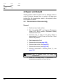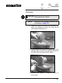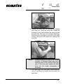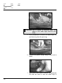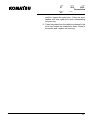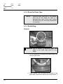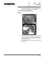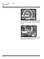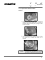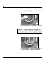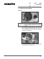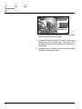
1
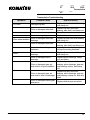
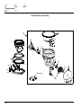
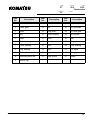
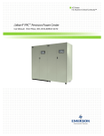
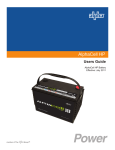
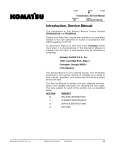
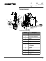
F-code
Section
PT
S2.0
2550
Transmission
Version no
C-code
T-code
000
Transmission
10
11
9
8
3
2
7
6
5
4
1
Transmission Mounting
Item No.
Komatsu
Master Service Manual
Description
1
Transmission assembly
2
Drive wheel assembly
3
Screw
4
Nut
5
Gear
6
Key
7
Plug, dipstick
8
Dipstick
9
O ring
10
Drive motor
11
Plug, fill
2004-03-15
141
F-code
Section
C-code
PT
S2.0
Transmission
2550
Version no
T-code
000
1. Theory of Operation
This transmission is of the double reduction gear type. The
gears are a combination of helical and bevel gears for
strength and low noise. The final drive gear is mounted on
opposing tapered roller bearings. Gears and bearings are
enclosed in an oil filled case. The drive motor is mounted
externally with the drive motor pinion gear mounted on the
armature shaft. The electric brake is on the drive motor.
2. Maintenance
See “Planned Maintenance Schedule” on page 69.
2.1. Fluid Changing
1. Remove drain plug (14, see page 144) from drive
unit and drain all the fluid.
2. Reinstall drain plug.
3. Remove fill plug (11, see page 141).
CAUTION Incorrect selection of fluid, for a particular
application, may cause damage.
4. Refill using the proper grade fluid (see page 82).
The capacity of the drive unit is 1-1/2 gallons (6
liters).
3. Troubleshooting
Because of the uncomplicated nature of the transmission,
troubleshooting is limited to identifying problems if they are
mechanical or electrical in nature. Fluid leaks are obviously
mechanical in nature and can be found by visual inspection.
Unusual noise and/or slow running could be mechanical or
electrical in nature. Generally speaking, if the problem is
caused internally in the transmission, then metal
contamination will be evident in the oil. If there is a
mechanical problem outside of the transmission, then it will
become evident by inspecting the drive motor and brakes.
142
Master Service Manual
2004-03-15
F-code
Section
PT
S2.0
2550
Transmission
Version no
C-code
T-code
000
Transmission Troubleshooting
Symptom
Oil Leaks
Probable Cause
Damaged lip seal
Worn or damaged axle shaft
Drive wheel wobbles
Gear case/main cover joint
Worn or damaged gear case
Worn or damaged axle shaft
bearings
Worn or damaged axle shaft
Noise
Loose wheel mounting
hardware
Worn or damaged axle shaft
bearings
Worn or damaged pinion
bearings
Worn or damaged gear set,
axle shaft is in good condition
Worn or damaged gear set,
axle shaft is worn or damaged
Worn or damaged helical gear
and pinion
Komatsu
Master Service Manual
2004-03-15
Required Action
Replace lip seal, axle shaft bearing
and clamp nut
Replace lip seal, axle shaft
bearing, axle shaft, and clamp nut
Reseal
Replace drive unit
Replace lip seal, axle shaft bearing
and clamp nut
Replace lip seal, axle shaft
bearing, axle shaft, and clamp nut
Inspect gear case for damage,
retorque mounting hardware
Replace lip seal, axle shaft bearing
and clamp nut
Replace pinion bearings, clamp
nut, and shims
Replace lip seal, axle shaft
bearing, pinion bearings, gear set
and bearings, shims, and clamp
nut
Replace lip seal, axle shaft
bearing, pinion bearings, gear set
and bearings, clamp nut, and axle
shaft
Replace helical gear and pinion
143
F-code
Section
C-code
PT
S2.0
Transmission
2550
Version no
T-code
000
Transmission Assembly
1
5
4
3
21
19
20
18
6
2
17
25
16
27
30 29
9
8
7
29
31
28
15
13
12
22, 23, 24
14
10
11
144
Master Service Manual
2004-03-15
F-code
Section
PT
S2.0
2550
Transmission
Version no
C-code
T-code
000
Komatsu
Item
No.
Description
Item
No.
1
Transmission assembly
12
Cover
22
Kit, seal
2
Case, gear
13
Nut
23
Kit, axle shaft
3
Gear
14
Plug, drain
24
Kit, drive gear
4
Nut
15
Cone, bearing
25
Kit, ring set
5
Gear
16
Shim
26
Ball
6
Cone, bearing
17
Bearing
27
Ring, pivot
7
Cone, bearing
18
Seal
28
Plug, bearing
8
Cup, bearing
19
Axle
29
Pin, spiral
9
Shim
20
Spacer
30
Fitting, grease
10
Gear and pinion set
21
Gear, pinion
31
Screw
11
Screw, cap
Master Service Manual
Description
2004-03-15
Item
No.
Description
145
F-code
Section
C-code
PT
S2.0
Transmission
2550
Version no
T-code
000
4. Repair and Rebuild
Visually inspect outside of gear case for damage, wear or
cracks. Excessive damage, wear, or cracks in the gear case
indicate that the transmission needs to be replaced rather
than repaired or rebuilt.
4.1. Transmission Disassembly
Removal
1. Park truck on a level surface.
2. Turn key switch OFF and depress Emergency
Power OFF (EPO) switch. Disconnect battery
connector from truck.
3. Jack the rear of truck so the drive wheel is
approximately 1 inch (25 mm) off the floor. Block
truck in this position.
4. Drain transmission fluid.
5. Remove drive tire (see page 192).
6. Remove steer motor (see page 207).
7. Remove drive motor (see page 129).
8. Remove transmission mounting bolts (3, see
page 141).
WARNING Use a suitable
transmission.
hoist
for
lifting
the
9. Attach an overhead hoist to transmission. Pull
transmission assembly out from the top.
146
Master Service Manual
2004-03-15
F-code
Section
PT
S2.0
2550
Transmission
Version no
C-code
T-code
000
Disassembly
CAUTION
NOTE!
Safety glasses are required.
Call-outs in the following procedures refer
to illustration on page 144.
1. Clean the outside of the drive unit thoroughly and
drain any remaining oil from the drive unit by
removing the drain plug (14).
2. Visually inspect the outside of the gear case (2) for
damage, wear or cracks. Pay particular attention to
the area where hub wear may be evident.
3. Remove cover screws (11) using a 1/2 inch (13
mm) socket.
Komatsu
Master Service Manual
2004-03-15
147
F-code
Section
C-code
PT
S2.0
Transmission
2550
Version no
T-code
000
4. Use a mallet to break the cover’s seal to the gear
case.
4.1.1. Pivot Ring
Removal
1. Remove the bearing filler plug screws (31) using a
1/2 inch (13 mm) socket.
2. Remove the bearing filler plug (28) with grease
fitting.
148
Master Service Manual
2004-03-15
F-code
Section
PT
S2.0
2550
Transmission
Version no
C-code
T-code
000
3. Remove the steel balls (26) through the bearing
filler plug hole. Work the steel balls forward by
inserting a putty knife between the pivot ring and
the gear case. Use care not to damage radial rings.
Move the pivot ring slightly from side to side while
working the putty knife toward the bearing filler
plug hole.
NOTE!
If the pivot ring will not spin or turn, it is an
indication of damaged radial rings and/or
excessive wear to the channel in the gear
case. If this is the case, replace the entire
drive unit. No further disassembly is
necessary.
4. After removing all the steel balls, remove the pivot
ring (27) by lifting it off toward the drive end of the
gear case.
Komatsu
Master Service Manual
2004-03-15
149
F-code
Section
C-code
PT
S2.0
Transmission
2550
Version no
T-code
000
CAUTION Due to normal or excessive wear, the
edges of the radial rings could be very
sharp.
5. Use a screwdriver to remove the radial rings (25)
and thrust ring from the pivot ring.
6. Remove the grease fittings using a punch and a
mallet.
7. Use a punch and mallet to remove the spiral pins
(29) that are used to hold the radial rings in
150
Master Service Manual
2004-03-15
F-code
Section
PT
S2.0
2550
Transmission
Version no
C-code
T-code
000
position. Inspect the spiral pins. If they are worn,
replace with new spiral pins when reassembling
the pivot ring.
8. Clean the grease from the radial ring channel in the
pivot ring. Inspect the channels for wear. If there is
excessive wear, replace the pivot ring.
Komatsu
Master Service Manual
2004-03-15
151
F-code
Section
C-code
PT
S2.0
Transmission
2550
Version no
T-code
000
4.1.2. Drive Unit Gear Case
NOTE!
Excessive gear case wear in the channel,
pivot ring or hub areas are signs of a
damaged gear case. If this occurs, replace
the entire drive unit. No further disassembly
is necessary.
4.1.3. Radial Ring
Removal
CAUTION Due to normal or excessive wear, the
edges of the radial rings could be very
sharp.
1. Use a screwdriver to remove the radial rings (25)
from the gear case.
2. Clean grease from the radial ring channel in the
gear case. Inspect the channel for uneven wear. If
152
Master Service Manual
2004-03-15
F-code
Section
PT
S2.0
2550
Transmission
Version no
C-code
T-code
000
there is excessive wear, no further disassembly is
necessary. The pivot ring must be replaced.
4.1.4. Axle Shaft and Bevel Gear
Removal
1. Loosen the setscrew locking the clamp nut (13)
using an Allen socket or wrench and a breaker bar.
An Allen wrench may be needed if the access is
limited by the location.
2. Use a screwdriver in the clamp nut slot to turn the
clamp nut off.
Komatsu
Master Service Manual
2004-03-15
153
F-code
Section
C-code
PT
S2.0
Transmission
2550
Version no
T-code
000
3. Use a brass drift punch and mallet to drive the axle
from the gear case. The brass drift punch will
reduce the risk of damaged threads on the end of
the axle.
4. Lift the bevel gear from the gear case. In cases
where severe chipping is present, a mallet may be
needed to knock the bevel gear loose.
154
Master Service Manual
2004-03-15
F-code
Section
PT
S2.0
2550
Transmission
Version no
C-code
T-code
000
4.1.5. Spiral Gear and Helical Gear
Removal
1. Turn the drive unit gear case over to remove the
clamp nut (4) from the spiral gear (3). Loosen the
setscrew locking the clamp nut (4) using an Allen
socket or wrench.
2. Use a screwdriver in the clamp nut (4) slot to turn
the clamp nut off. Inspect the clamp nut for
damage.
NOTE!
Komatsu
Master Service Manual
The spiral pinion may need to be removed
with a press or equivalent pressing device.
2004-03-15
155
F-code
Section
C-code
PT
S2.0
Transmission
2550
Version no
T-code
000
3. Use a brass drift punch and mallet to drive the
spiral gear through the gear case. The brass drift
punch will reduce the risk of damaged threads on
the end of the spiral shaft.
4. Lift the helical gear (3) and spacer (20) from the
gear case.
NOTE!
The bevel gear and spiral gear are a
matched set. Their alignment is critical. Do
not replace them separately.
5. Inspect the helical gear and the spiral gear for
damage or wear.
6. To remove bearing (6), remove the spiral shaft (10)
from the gear case. Lift bearing from gear case.
156
Master Service Manual
2004-03-15
F-code
Section
PT
S2.0
2550
Transmission
Version no
C-code
T-code
000
4.1.6. Bearing Cup and Shim
Removal
NOTE!
Because the bearing cups and cones are
usually damaged during removal, replace
as sets.
1. Use a mallet and long punch to drive the spiral
gear bearing cup (8) from the gear case. Take care
not to damage the shims. Save the shims for
reference in reassembly.
2. Use the mallet and a punch to drive the helical gear
bearing cup from the gear case.
Komatsu
Master Service Manual
2004-03-15
157
F-code
Section
C-code
PT
S2.0
Transmission
2550
Version no
T-code
000
BEVEL GEAR
BEARING CUP
AXLE SHAFT
BEARING CUP
3. Remove the axle shaft bearing cup from the gear
case using the punch and mallet.
4. Use the mallet and a punch to drive the bevel gear
bearing cup from the gear case. Take care not to
damage the shims. Save the shims for reference in
reassembly.
5. Visually inspect the gear case bores and sealing
surfaces for damage or wear.
158
Master Service Manual
2004-03-15
F-code
Section
PT
S2.0
2550
Transmission
Version no
C-code
T-code
000
4.1.7. Spur Gear
Removal
Check the spur gear for damage or wear. If the spur gear is
damaged, use a drift punch and mallet to remove it from the
gear case.
Komatsu
Master Service Manual
2004-03-15
159