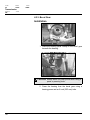
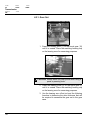
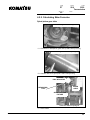
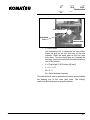
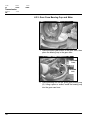
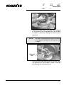
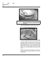
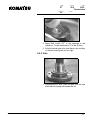
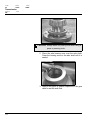
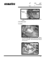
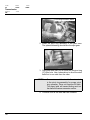
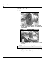
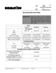
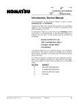
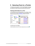
1
F-code
Section
C-code
PT
S2.0
Transmission
2550
Version no
T-code
000
4.2. Transmission Reassembly
CAUTION
Safety glasses are required.
4.2.1. Gear Case
Prepare the gear case for assembly by running a tap through
all bolt and screw holes. Cleaning the threads ensures there
is no damage and enables you to determine if the gear case
has standard or metric threads. It also enables you to
determine the proper tooling to use in the assembly process.
Before beginning the assembly of the drive unit, record the
bearing seat data stamped on the gear case. Record the
setting distance information stamped on the bevel and spiral
gears. This data will be used in the formula to determine shim
thickness.
Cleaning and Inspection
Thoroughly degrease the gear case. Visually inspect the
entire gear case again for excessive damage, cracks or wear.
4.2.2. Axle Shaft
Installation
1. Place a bearing puller clamp between the axle seal
and beneath the axle bearing cone.
160
Master Service Manual
2004-03-15
F-code
Section
PT
S2.0
2550
Transmission
Version no
C-code
T-code
000
CAUTION Always watch for pinch points when using a
press or pressing tools.
2. Press the bearing from the axle using a bearing
press and a 6 inch (152 mm) tube.
3. Lift axle seal from the axle.
4. Inspect the axle for damage or wear.
Komatsu
Master Service Manual
2004-03-15
161
F-code
Section
C-code
PT
S2.0
Transmission
2550
Version no
T-code
000
4.2.3. Bevel Gear
Installation
1. Place the bearing puller clamp on the bevel gear
beneath the bearing.
CAUTION Always watch for pinch points when using a
press or pressing tools.
2. Press the bearing from the bevel gear using a
bearing press and an 8 inch (203 mm) tube.
162
Master Service Manual
2004-03-15
F-code
Section
PT
S2.0
2550
Transmission
Version no
C-code
T-code
000
4.2.4. Spiral Gear
Installation
1. Place a bearing puller clamp beneath the bearing
cone on the spiral gear.
CAUTION Always watch for pinch points when using a
press or pressing tools.
2. Press the bearing from the spiral gear using a
bearing press.
Komatsu
Master Service Manual
2004-03-15
163
F-code
Section
C-code
PT
S2.0
Transmission
2550
Version no
T-code
000
4.2.1. Gear Set
1. Press the bearing cone (7) on the bevel gear (10)
until it is seated. Place the matching bearing cup
on the bearing cone for measuring purposes.
CAUTION Always watch for pinch points when using a
press or pressing tools.
2. Press the bearing cone (6) on the spiral gear (3)
until it is seated. Place the matching bearing cup
on the bearing cone for measuring purposes.
3. Use the bearing zero offset tool and the following
formulas to determine the shim thickness that will
be required to assemble the gear set in the gear
case.
164
Master Service Manual
2004-03-15
F-code
Section
PT
S2.0
2550
Transmission
Version no
C-code
T-code
000
4.2.2. Calculating Shim Formulas
Spiral pinion gear shim
Record bearing seat data from gear case
• A = Dimension A stamped on gear case (4.438 inches [113 mm])
Record bearing seat data from spiral gear
• B = Number etched on gear (S/D 2.378 inches [60 mm])
DIAL INDICATOR
PINION
GEAR
MEASURING
TOOL
GEAR CHECKING
FIXTURE
Check zero offset of spiral gear
• C = Zero Offset
Komatsu
Master Service Manual
2004-03-15
165
F-code
Section
C-code
PT
S2.0
Transmission
2550
Version no
T-code
000
Use measuring tool (see page 165) to determine
the zero offset. Place the plug on the tool and zero
out the dial indicator. Place the spiral gear in the
tool, shaft end down. Turn the spiral gear as if
seating the bearings. Record the data from the dial
indicator to use in the formula.
•
D = Plug Height (2.025 inches [51 mm])
•
E=B+C+D
•
F=A-E
F = Shim thickness required
This calculation is used to determine the shim amount behind
the bearing cup in the main gear case. The shim(s)
position(s) the spiral gear for proper backlash.
Bevel gear shim
Record bearing seat data from gear case
• G = Dimension B stamped on gear case (2.506 inches [64 mm])
Record bearing seat data from bevel gear
• H = Number etched on gear (S/D 0.541 inches [14 mm])
166
Master Service Manual
2004-03-15
F-code
Section
PT
S2.0
2550
Transmission
Version no
C-code
T-code
000
Check zero offset of spiral gear
DIAL INDICATOR
MEASURING
TOOL
CROWN GEAR
•
J = Zero Offset
Use measuring tool to determine the zero offset.
Place the plug on the tool and zero out the dial
indicator. Place the bevel gear on the tool, race
side down. Turn the bevel gear as if seating the
bearings. Record the data from the dial indicator to
use in the formula.
•
K = Plug height (1.875 inches [48 mm])
•
L=H+J+K
•
M=G-L
M = Shim thickness required
This calculation is used to determine the shim amount behind
the bearing cup in the main gear case. The shim(s)
position(s) the bevel gear for proper backlash.
Komatsu
Master Service Manual
2004-03-15
167
F-code
Section
C-code
PT
S2.0
Transmission
2550
Version no
T-code
000
4.2.3. Gear Case Bearing Cup and Shim
1. Place the spiral gear shims in the gear case, then
place the bearing cup in the gear case.
PRESSING
TOOL
BEARING
CUP
2. Place pressing tool on the spiral gear bearing cup
(8). Using a press or mallet, install the bearing cup
into the gear case bore.
168
Master Service Manual
2004-03-15
F-code
Section
PT
S2.0
2550
Transmission
Version no
C-code
T-code
000
3. Place bevel gear shim in the gear case, followed
by the bearing cup. Use pressing tool with a press
or mallet to press the bearing cup into the gear
case bore.
NOTE!
Be sure to wipe away any chips or excess
metal pieces resulting from driving the race
to seat it.
PRESSING
TOOL
4. Place the drive axle bearing cup in the gear case.
Use pressing tool and a mallet or press to seat the
axle bearing cup in the gear case.
Komatsu
Master Service Manual
2004-03-15
169
F-code
Section
C-code
PT
S2.0
Transmission
2550
Version no
T-code
000
5. Turn the drive unit gear case over. Install the
helical bearing cup in the gear case. Use pressing
tool and a press or mallet to seat the bearing cup in
the gear case.
4.2.4. Helical Gear/Spiral Pinion Gear
WARNING Bearing can become extremely hot. Use
gloves to protect hands from burns.
NOTE!
The pinion shaft and bevel gear are a
matched set. Their alignment is critical. Do
not replace separately.
1. Preheat the bearing cone (6) with a bearing heater.
170
Master Service Manual
2004-03-15
F-code
Section
PT
S2.0
2550
Transmission
Version no
C-code
T-code
000
NOTE!
Steps 2 through 5 need to be completed
before the bearing cools to provide a proper
installation.
2. Install the heated bearing cone in the bearing cup
in the gear case.
3. Place the spacer over the bearing cone, then place
the helical gear (3) into the gear case.
4. Install the spiral pinion (10) up through the helical
gear (3). Push up until the spiral gear bearing is
seated against its race.
Komatsu
Master Service Manual
2004-03-15
171
F-code
Section
C-code
PT
S2.0
Transmission
2550
Version no
T-code
000
NOTE!
Steps 2 through 5 need to be completed
before the bearing cools to provide a proper
installation.
5. Place the clamp nut (4) on the end of the spiral
pinion and hand tighten until the bearing cools.
6. When the bearing has cooled, spin the helical gear
to check for end play. Remove any end play in the
bearings between the helical gear (3) and the spiral
gear (10) using a nut driver tool and a wedge.
Slowly tighten the clamp nut (4) on the end of the
spiral gear until there is no end play between the
gears. Use a spin and tighten method to tighten
clamp nut (4) as the bearings are seating in the
races.
7. Tighten clamp nut (4) the distance of a spanner nut
space to preload the gears. Back the nut off, then
hand tighten.
172
Master Service Manual
2004-03-15
F-code
Section
PT
S2.0
2550
Transmission
Version no
C-code
T-code
000
8. Apply Red Loctite 271® to the setscrew in the
clamp nut. Torque setscrew to 70 in-lbs (8 N•m).
9. Spin the helical gear to be sure there is no end play
or that the bearings are not too tight.
4.2.5. Axle
1. Lubricate the oil seal. Place the seal over the axle
shaft with the spring side toward the oil.
Komatsu
Master Service Manual
2004-03-15
173
F-code
Section
C-code
PT
S2.0
Transmission
2550
Version no
T-code
000
CAUTION Always watch for pinch points when using a
press or pressing tools.
2. Place the axle bearing cone over the axle shaft.
Press the bearing cone on the axle shaft until it is
seated.
3. Apply a thin layer of gasket compound to the gear
case to seal the axle seal.
174
Master Service Manual
2004-03-15
F-code
Section
PT
S2.0
2550
Transmission
Version no
C-code
T-code
000
4. Place the bevel gear into the gear case.
PRESSING
TOOL
5. Place pressing tool beneath the axle seal. Install
the axle shaft through the bevel gear.
CAUTION Always watch for pinch points when using a
press or pressing tools.
6. Press the axle into the gear case until the seal is
fully installed.
Komatsu
Master Service Manual
2004-03-15
175
F-code
Section
C-code
PT
S2.0
Transmission
2550
Version no
T-code
000
7. Remove the seal driver tool.
8. Apply Red Loctite 271® to the threads of the axle.
9. Install the clamp nut (13). Hold the axle to keep it
from turning as the clamp nut is tightened. Torque
the clamp nut to 18 ft-lbs (24 N•m).
ROTATING
DEVICE
10. Install a rotating device on the end of the axle.
11. Rotate the axle and tighten the clamp nut. Repeat
this step six times to be sure the bearing cones are
seated into the cups.
12. Loosen the clamp nut, retighten to 5 ft-lbs (7 N•m)
using the rotating device. Tighten until the clamp
nut does not turn.
13. Apply Red Loctite 271® to the setscrew in the
clamp nut. Torque the setscrew to 70 in-lbs (8
N•m).
176
Master Service Manual
2004-03-15
F-code
Section
PT
S2.0
2550
Transmission
Version no
C-code
T-code
000
4.2.6. Measuring Backlash
HOUSING
GEAR
FIXTURE
CROWN
GEAR
GEAR LOCKING
TOOL
NOTE!
Backlash tolerance is critical to the
performance of the drive unit. Units
adjusted improperly will cause premature
failure.
1. Place the gear locking tool on the helical gear and
secure.
CROWN
GEAR
DIAL
INDICATOR
2. Position probe of the dial indicator at the heel of the
bevel gear tooth. The dial indicator probe should
be perpendicular to the gear tooth surface.
Komatsu
Master Service Manual
2004-03-15
177
F-code
Section
C-code
PT
S2.0
Transmission
2550
Version no
T-code
000
MANIPULATOR
GEAR
LOCKING
FIXTURE
R
CROWN
GEAR
DIAL
INDICATOR
NOTE!
TRANSMISSION
HOUSING
Backlash tolerance is critical to the
performance of the drive unit. Units
adjusted improperly will cause premature
failure.
3. Zero the indicator.
and rotate it. Read
the dial indicator.
between 0.004 and
mm).
Clasp the bottom of the gear
the backlash measurement on
Total backlash tolerance is
0.006 inch (0.1016 and 0.1524
4. If the tolerance is not within the acceptable limits,
calculate necessary adjustments to the shims.
Remove the clamp nut, axle assembly and bevel
gear. Install the proper amount of shims, and
repeat Steps 3 and 4 (see “Gear Case Bearing
Cup and Shim” on page 168). Repeat steps 1
through 3 above until the backlash is between
0.004 and 0.006 inch (0.1016 and 0.1524 mm).
5. When backlash is within the acceptable range,
install the pivot ring.
178
Master Service Manual
2004-03-15
F-code
Section
PT
S2.0
2550
Transmission
Version no
C-code
T-code
000
4.2.7. Pivot Ring
Assembly
1. Place a light coating of Red Loctite 271® in the hole
on the pivot ring assembly.
2. Line up the grease fitting hole with the grease
fitting port.
3. Install the grease fitting (30) in the pivot ring (27)
assembly using a grease fitting driver and a mallet
or press.
Komatsu
Master Service Manual
2004-03-15
179
F-code
Section
C-code
PT
S2.0
Transmission
2550
Version no
T-code
000
4. On the inside of the pivot ring (27), be sure the
spiral pins (29) are installed and in good condition
on either side of the bearing filler plug hole. Install
new spiral pins if they are missing or damaged.
RADIAL
RINGS
SPIRAL
PINS
5. Install the radial rings (25) so that the gap aligns
with the bearing hole. Install the flat radial ring on
the inside flat surface of the pivot ring. Install
chamfered radial rings to the pivot ring. The
chamfered edges will face the steel balls. The ends
of the radial ring will be against the spiral pins (29).
180
Master Service Manual
2004-03-15
F-code
Section
PT
S2.0
2550
Transmission
Version no
C-code
T-code
000
BUSHING
TOOL
6. Install the brass bushing using tool and a mallet or
press.
4.2.8. Drive Unit
Assembly
1. Install the radial rings (5) on the gear case. Stagger
the ends of the rings around the gear case so the
gaps are not aligned. The beveled edges will face
the steel balls.
Pivot Ring Installation
Komatsu
Master Service Manual
2004-03-15
181
F-code
Section
C-code
PT
S2.0
Transmission
2550
Version no
T-code
000
Pivot Ring Installation, Metric
2. Install the pivot ring assembly to the gear case.
The spherical bearing should face the spur gear.
3. Place one steel ball (26) at a time into the pivot ring
(27) filler hole. Use a screwdriver to direct the steel
balls first to one side then the other.
NOTE!
Be sure to count the steel balls as inserted
in the pivot ring assembly for proper pivot
ring operation. Drive unit requires 65 balls.
Too many balls will cause binding and too
few balls will cause excessive motion.
4. Continue until all the steel balls are installed.
182
Master Service Manual
2004-03-15
F-code
Section
PT
S2.0
2550
Transmission
Version no
C-code
T-code
000
5. Place the bearing filler plug (28) in the filler hole.
The grease fitting (30) should face the spur gear.
CAUTION Excessive thread locking compound will
damage the ball bearings and pivot ring.
Use thread locking compound sparingly.
6. Apply Loctite 242® sparingly to the filler plug bolts
(31). Install the bolts on each side of the grease
fitting (30). Tighten to 20 ft-lbs (27 N•m).
7. Grease and test the pivot ring to make sure it spins
freely.
Komatsu
Master Service Manual
2004-03-15
183
F-code
Section
C-code
PT
S2.0
Transmission
2550
Version no
T-code
000
4.2.9. Gear Case Cover
Installation
1. Clean the cover mating surface. Apply Loctite 587®
to the surface where the cover (12) contacts the
gear case (2).
2. Install the cover bolts (11) and torque to 20 ft-lbs
(27 N•m).
NOTE!
Use cover mounting bolts to mount the
cover.
3. Apply thread locking compound to the drain plug
(14). Install the drain plug in the cover plate and
torque to 15 ft-lbs (20 N•m).
184
Master Service Manual
2004-03-15